Page 1 of 8
VKey Voltage Keypad Hookup Guide
Introduction
If you need to add a keypad to your microcontroller project, but don’t want
to use up a lot of I/O pins to interface with it, the VKey is the solution for
you. It outputs an analog voltage to encode which key has been pressed,
which can in turn be read by an analog to digital converter on a
microcontroller.
VKey Voltage Keypad
Traditional digital keypad interfacing techniques can require a large number
of digital I/O lines. One common arrangement uses N digital outputs and M
digital inputs to interface with an N*M array of keys, as described here. On
a small controller, there may not be many I/O pins left for other tasks.
The VKey board has 12 pushbutton switches and some supporting circuitry.
It outputs an analog voltage that represents which of the keys is being
pressed. This output can be sampled using a single channel of ADC,
allowing 12 keys to be scanned using a single analog input pin.
Covered In This Tutorial
This tutorial will guide you through connecting the VKey to an Arduino, and
it introduces a library that tells the application which key is currently
pressed.
Required Materials
•
•
•
•
VKey Voltage Keypad
Arduino, RedBoard or any Arduino-compatible board.
Male PTH headers or right angle PTH headers.
Jumper Wires
�Page 2 of 8
Suggested Reading
•
•
•
•
•
•
•
Voltage, Current, Resistance, and Ohm’s Law
What is an Arduino?
Switch Basics
How to Solder
Working with Wire
Analog to Digital Conversion
Voltage Dividers
Board Overview
Looking at the front of the board, we see an 3 by 4 array of tactile switches
and three connection pads near the bottom edge of the board.
Front of VKey
The connection pads are as follows.
GND should be connected to the ground of the host circuit.
Vout is the analog output of the keypad, and should be connected to an
analog-to-digital channel (such as A0, A1, etc on an Arduino).
V+ is the power supply, and should be connected to a voltage between
3.3V - 5.5V.
How It Works
Take a look at the back of the VKey.
Back of VKey
�Page 3 of 8
The IC is a dual opamp, used as a current source and buffer amplifier. The
current source drives a string of resistors that form a voltage divider, and
the tact switches select voltages at the different taps of the divider.
See the resources section for links to a much more detailed guide to the
internals of the VKey.
Each of the buttons on the VKey produces a unique analog voltage, as
listed below/
Key Number
None
12
11
10
9
8
7
6
5
4
3
2
1
Vout (5V supply)
.057
.198
.396
.596
.794
.992
1.190
1.388
1.585
1.781
1.979
2.176
2.372
Vout (3.3V supply)
.053
.194
.388
.583
.776
.970
1.164
1.358
1.551
1.744
1.938
2.131
2.323
As you can see, with a 5V supply, each successive button adds about 200
mV to the output voltage – at 3.3V the voltage per step is slightly less.
One situation to consider is when more than one key is pressed at the
same time. The VKey implements high-key number (or low voltage) priority
– when more than one of the switches is closed at a time, the output will
indicate the higher key number. For instance, if you hold down 5 and 9
together, the output will indicate key 9 is pressed.
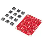
Assembly
The VKey comes with the surface mount components assembled, but the
PTH tactile switches are loose, and need to be soldered to the board.
Contents of the VKey package
The first step in hooking up the VKey is to solder in the key switches.
�Page 4 of 8
Attaching the tact switches
Depending on how the board is to be mounted, different headers can be
soldered to the board.
If the overall depth of the assembly is a concern, you can use a right angle
header on the same side of the board as the tact switches.
Right angle header on top of board
If clearance past the edge of the board is a concern, you can use a straight
header soldered to the side opposite the switches.
Straight header on back of board
And of course, you could always solder wires directly to the board in place
of the header.
Connecting The VKey To An Arduino
Basic hookup to an Arduino
It takes three wires to connect the VKey to an Arduino.
(VKey → Arduino)
• V+ → 5V
• Vout → A1 (or any other analog pin)
• GND → GND
Arduino Library
�Page 5 of 8
To make interfacing the VKey as simple as possible, we’ve written an
Arduino library and example sketch. If you need a refresher on how to
install an Arduino library, please see our library tutorial.
The VKey library provides an object that interfaces with a VKey keypad. In
a typical application, this class is instantiated as a global object before the
setup() function. In the VKey object declaration, you need to select the
appropriate analog input pin, and set the power indication to the proper
voltage, either THREE (actually shorthand for the more common 3.3V) or
FIVE .
It is possible to attach several VKeys, each on it’s own analog input pin, by
declaring multiple VKey objects to watch the corresponding analog pin
numbers.
The VKey status is queried using the function
bool CheckKeys(eKeynum & k);
The function will always return an indication of the current button in
reference parameter k, or NONE in the case that no buttons are pressed.
The function also returns a boolean indication of whether the key has
changed since the last time it was queried – a form of edge detection. Many
applications will only care about handling the key number when it updates,
and don’t need to process the input when it is unchanging.
The next page will show us a quick sample sketch that uses the VKey
library.
Example Code
Once you have installed the library, open the Arduino IDE, and paste the
following into the sketch:
�Page 6 of 8
/*************************************************************
*****************
VKey_demo_main.ino
VKey Voltage Keypad decoding demo
By Byron Jacquot @ @ SparkFun Electronics
February 4, 2014
https://github.com/sparkfun/VKey_Voltage_Keypad
This demonstrates interfacing the SparkFun VKey voltage keypa
d using
the VKey Arduino library.
The VKey has an array of 12 pushbuttons, each producing a uni
que analog
voltage when pushed. A microcontroller can read the voltag
e, and determine
which key has been pressed. The VKey library keeps track of
the analog pin
connection, key status, and voltage calibration details.
The VKey was connected to the Arduino as follows:
VKey GND > Arduino GND
VKey Vout > Arduino analog input A1
VKey V+ > Arduino VCC
To use the library, instantiate a VKey object and periodicall
y check for input
using the checkKeys() function.
Resources:
no additional library requirements
Development environment specifics:
Developed on Arduino IDE 1.0.5
Tested on a 5V Redboard and 3.3V Pro Mini
This code is beerware; if you see me (or any other SparkFun e
mployee) at the
local, and you've found our code helpful, please buy us a rou
nd!
Distributed asis; no warranty is given.
**************************************************************
****************/
#include
// Global declaration of the VKey class
// Initialized with analog pin number and supply voltage
VKey keypad(A1, VKey::FIVE );
void setup()
{
// Initialize serial port for text output
Serial.begin(9600);
Serial.println("Welcome to VKey example");
// No VKey specific initialization required.
}
void loop()
{
VKey::eKeynum k; // Variable to receive the key indication
�Page 7 of 8
/* CheckKeys will always return the current key in paramet
er k.
The boolean return value indicates whether that value i
s different than
the previous value.
*/
if(keypad.checkKeys(k))
{
// Only print when value has changed
Serial.print("Got key: ");
Serial.println(k);
}
// The responsiveness of the keypad depends on how frequentl
y it is checked.
// 50 milliseconds seems to be a reasonable poll interval.
delay(50);
}
Build and upload the sketch. Then open a serial terminal, and observe the
output while pressing buttons.
The Arduino recognizes keys based on the voltage produced by the VKey
The Arduino will print notifications as buttons are pressed and released. A
key number of 0 indicates that no keys are currently pressed.
If the Arduino isn’t properly tracking the key numbers, double-check that the
VKey object was declared with the proper analog pin and supply voltage
parameters. Also doublecheck that you’ve got the latest code from the
Github repository.
Resources And Going Further
The VKey is a great way to add up to 12 buttons to a project, while still
leaving many I/O pins for other tasks.
The schematics, PCB artwork and source code for the VKey are all found
on it’s Github page. For a deeper look at the internals of the VKey, check
the documents directory found there. You’ll find a more detailed theory of
operations document, with supporting SPICE simulations and
spreadsheets.
• Github Repository
Modifications
There are a number of possible alterations that can be made to the VKey,
to tailor it to a specific application.
Different Switches
The VKey comes with 12 PTH pushbutton switches, but can support nearly
any normally-open SPST switch, such as arcade buttons or microswitches.
�Page 8 of 8
Connect alternate switches across the left pair of pads
To connect other switches, connect them to the pair of pads on the left of
the tact switch footprint, as seen from the front of the board.
Voltage Source
While the VKey is primarily intended to interface with a microcontroller, that
doesn’t mean it can’t be used for other applications. The circuit is similar to
those used in analog synthesizers to extract a control voltage from the
piano keyboard. You could use the VKey to drive any device with a control
voltage input.
https://learn.sparkfun.com/tutorials/vkey-voltage-keypad-hookup-guide?_ga=1.43518693.1...
8/5/2016
�


 工商网监
湘ICP备2023018690号
工商网监
湘ICP备2023018690号
