AP.25F.07.0078A
Specification
Part No.
AP.25F.07.0078A
Product Name
25mm Two Stage GPS Active Patch Antenna Module with
front-end Saw Filter
Feature
Industry leading GPS antenna performance
25mm*25mm*8mm (Ground Plane)
78mm Ø1.13 I-PEX MHFI (U.FL)
28dB LNA
Wide Input Voltage 1.8V to 5.5V
Low Power Consumption
ROHS Compliant
SPE-11-8-030/A |
page 1 of 11
�1. Introduction
The AP.25F has been designed specifically
for embedded (inside device) integration
with GPS receiver modules where there is a
GSM transmitter nearby and risk of
interference and saturation.
The AP.25F combines a 25*25*4mm
advanced low profile ceramic patch
antenna with a two stage LNA and a
front-end SAW filter, with ultra thin
coaxial cable.
Taoglas active antenna modules utilise
XtremeGainTM technology for the highest
sensitivity in the industry. The AP.25F
consists of 2 functional blocks – the LNA
and also the patch antenna.
ANTENNA
SAW Filter
LNA
LNA
I-PEX + cable
The AP.25F has a SAW filter on the front of
it. The main use of the AP.25F would be for
small devices where the GSM transmitter
is close to the GPS antenna, it helps avoid
burn-out of the LNA or the module due to
interference from the GSM transmitter at out
band frequencies.
SPE-11-8-030/A |
page 2 of 11
�2. Specification
2.1 Patch Antenna
Parameter
Specification
Frequency
1575.42 ± 1.023MHz
Gain @ Zenith
+2.0 dBic Typ. @ Zenith
Polarization
RHCP
Axial Ratio
3.0dB max. @ Zenith
Patch Dimension
25*25*4mm
2.2 LNA
Parameter
Specification
Frequency
Outer Band Attenuation
1575.42 ± 1.023MHz
F0=1575.42MHz
F0±30MHz
5dB min.
F0±50MHz
20dB min.
F0±100MHz
Output Impedance
50Ω
Output VSWR
2.0 Max
Typ. -2dBm
Min. -6dBm
Pout at 1dB Gain
Compression point
25dB min.
LNA Gain, Power Consumption and Noise Figure
Voltage
LNA Gain (Typ)
Power Consumption(mA) Typ
Noise Figure Typ
Min. 1.8V
23dB
Min. 3mA - Max. 10mA
2.7dB
Typ. 3.0V
28dB
Min. 8mA – Max. 20mA
3.0dB
Max. 5.5V
30dB
Min. 30mA – Max. 40mA
3.7dB
2.3 Cable* & Connector
Parameter
Specification
RF Cable
Coaxial Cable Ø1.13 ± 0.1mm, length 80 ± 2.0mm
Connector
IPEX MHFI (U.FL)
SPE-11-8-030/A |
page 3 of 11
�3. LNA Gain and Out Band Rejection @3.0V
Tr1
S21 Log Mag 10.00dB/ Ref -40.00dB (F2)
60.00
>1 1.5754200 GHz 30.649 dB
50.00
40.00
1
30.00
3
20.00
10.00
5
0.000
7
-10.00
2
-20.00
1
4
6
-30.00
-40.00
1 Center 1.57542 GHz
IFBW 70 Hz
Cg1 Tr1 S21
>1
1.5754200 GHz
30.649
dB
Cg1 Tr1 S21
2
1.6054200 GHz
-6.7098
dB
Cg1 Tr1 S21
3
1.5454200 GHz
24.584
dB
Cg1 Tr1 S21
4
1.6254200 GHz
-5.6354
dB
Cg1 Tr1 S21
5
1.5254200 GHz
8.0734
dB
Cg1 Tr1 S21
6
1.6754200 GHz
-15.436
dB
Cg1 Tr1 S21
7
1.4754200 GHz
1.5714
dB
Span 400 MHz 18/20 Cor
SPE-11-8-030/A |
page 4 of 11
�4. LNA Noise Figure @3.0V
Mkr1
1.5754 GHz
2.909 dB
30.298 dB
9.000
NFIG
Scale/
1.000
dB
1
-1.000
40.00
1
GAIN
Scale/
5.000
dB
-10.00
Center 1.57542 GHz BW 4 MHz
Tcold 296.50 K
Avgs 16
Points 11
Att 0/ - - dB
Span 3.00 MHz
Loss Off
Corr
5. Total Specification (through Antenna, LNA, Cable and Connector)
Parameter
Specification
Frequency
1575.42 ± 1.023MHz
Gain
At 3V: 30 ± 3dBic @ 90°
Output Impedance
50Ω
Polarization
RHCP
Output VSWR
Max 2.0
Operation Temperature
-40°C to + 85°C
Storage Temperature
-40°C to + 85°C
Relative Humidity
40% to 95%
Input Voltage
Min. 1.8V, Typ. 3.0V, Max. 5V
Antenna
25*25*8mm
SPE-11-8-030/A |
page 5 of 11
�6. Radiation Patterns
6.1 XZ Plane Radiation
0
8
5
0
-5
-10
-15
-20
-25
-30
-35
-40
90
270
180
Pattern
1
Model No.
AP.25F.07.0078A
Test Mode Freq (MHz) Max Gain(dBi) Min Gain(dBi)
XZ
1610.00
0.59 / 6.00
-14.77 / 134.00
Avg. Gain(dBi) Source Polar.
-4.16
RHCP
SPE-11-8-030/A |
Date
2010/4/19
page 6 of 11
�6.2 YZ Plane Radiation
0
8
5
0
-5
-10
-15
-20
-25
-30
-35
-40
90
270
180
Pattern
1
Model No.
AP.25F.07.0078A
Test Mode Freq (MHz) Max Gain(dBi) Min Gain(dBi)
YZ
1610.00
0.17 / 356.97 -14.85 / 121.35
Avg. Gain(dBi) Source Polar.
-4.75
RHCP
SPE-11-8-030/A |
Date
2010/4/19
page 7 of 11
�6.3 XY Plane Radiation
0
8
5
0
-5
-10
-15
-20
-25
-30
-35
-40
90
270
180
Pattern
Model No.
Test Mode Freq (MHz) Max Gain(dBi)
Min Gain(dBi)
Avg. Gain(dBi) Source Polar.
Date
1
AP.25F.07.0078A
XZ
1610.00
0.59 / 6.00
-14.77 / 134.00
-4.16
RHCP
2010/4/19
2
AP.25F.07.0078A
YZ
1610.00
0.17 / 356.97 -14.85 / 121.35
-4.75
RHCP
2010/4/19
SPE-11-8-030/A |
page 8 of 11
�7. Technical Drawing
A
ALL Initial Design
A
Kiwi
ALL Initial Design
2011/7/11
Kiwi
2011/7/11
Connector IPEX MHF1
Connector IPEX MHF1
Top
Top
Side
Side
Bottom
Name
Name
1
Patch(25*25*4mm)
2
1.13 Coaxial Cable
1
Patch(25*25*4mm)
2
1.13 Coaxial
Cable
3
IPEX MHF1
3
IPEX MHF1
4
PCB
4
PCB
Shielding Case
5
Shielding Case
5
"A"
Bottom
"A"
Material
Material
Name
Finish
QTY
Finish
QTY Finish
Material
QTY
Ceramic
Clear
1
NOTE:
1 Ceramic
Patch(25*25*4mm)Clear Ceramic 1
Clear
1
NOTE:
1.Soldered area NOTE:
FEP
1
Gray
1.Soldered
area
2.All
material
must
RoHS
compliant.
Soldered
area
2 FEP
1.13 Coaxial Cable Gray
FEP
1 1.be
Gray
1
Brass
Gold
1
2.Allhas
material
3.The connector orientation
a fixedmust be RoHS compliant.
2. All material
must be RoHS compliant.
3
IPEX MHF1
Brass
Gold
connector
position
to the1antenna3.The
as per
drawing. orientation has a fixed
Brass
Gold
Green
1 1
FR4 0.8t
3.
The
connector
a fixed
position
to the orientation
antenna as perhas
drawing.
Green
1
4 PCB
FR4 0.8t
Tin Plated
1 1
position to the antenna as per drawing.
FR4(Tin)SPTE
0.8t
Green
5
Shielding Case
Tin Plated
1
(Tin)SPTE
(Tin)SPTE
Tin Plated
1
TW Design Centre
This drawing and its inherent design concepts are property of Taoglas. Not to
TW Design Centre
be copied or given to third parties without the written consent of Taoglas.
This drawing and its inherent design concepts are property of Taoglas. Not to
be copied or given to third parties without the written consent of Taoglas.
SPE-11-8-030/A |
page 9 of 11
�8. Plugs Usage Precautions
8.1 Mating / unmating
(1) To disconnect connectors, insert the
end portion of I-PEX under the connector
flanges and pull off vertically, in the direction of the connector mating axis.
Coaxial Cable
(2) To mate the connectors, the mating
axes of both connectors must be aligned
and the connectors can be mated. The
“click” will confirm fully mated connection.
Do not attempt to insert on an
extreme angle.
2
PLUG
1
Pulling Tool
P/N : 90192-001
RECEPTACLE
8.2 Pull forces on the cable after connectors are mated
After the connectors are mated, do not
apply a load to the cable in excess of the
values indicated in the diagram below.
2N MAX.
PLUG
4N MAX.
2N MAX.
RECE
Coaxial Cable
SPE-11-8-030/A | page 10 of 11
�Taoglas makes no warranties based on the
accuracy or completeness of the contents
of this document and reserves the right to
make changes to specifications and
product descriptions at any time
without notice.
Taoglas reserves all rights to this document
and the information
contained herein. Reproduction, use or
disclosure to third parties without
express permission is strictly prohibited.
Copyright © 2012, Taoglas Ltd.
SPE-11-8-030/A | page 11 of 11
�
很抱歉,暂时无法提供与“AP.25F.07.0078A”相匹配的价格&库存,您可以联系我们找货
免费人工找货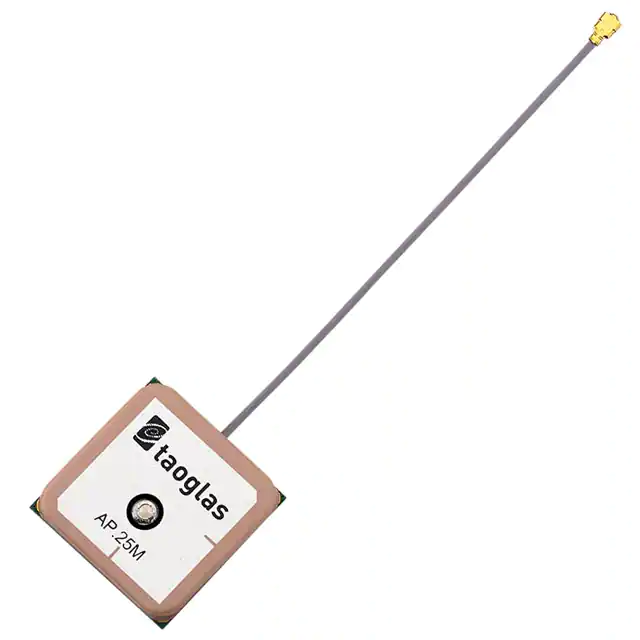


 工商网监
湘ICP备2023018690号
工商网监
湘ICP备2023018690号
