Specification
Spec No.
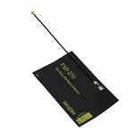
: FXP270
Part No.
: FXP270.07.0100A
Model
: 784MHz ISM Band Flex Circuit Antenna
Features
: 75*45*0.1mm
100mm Ø1.13 Cable
RoHS
VERSION
DATE
PAGE
DESCRIPTION
CENTRE
APPROVED
A
09/21/2009
All
Antenna Specifications
Taiwan
Ruben F. Cuadras
© All Rights Reserved
Taoglas Limited, Unit 7 Peare Campus, Moyne Business Park, Enniscorthy, Co. Wexford, Ireland
info@taoglas.com
+353 53 9169500
www.taoglas.com
�I. OVERVIEW
The Taoglas FXP270 784 MHz ISM Band Antenna covers from 779-787 MHz used in the 784
MHz ISM (Industrial Scientific Medical) Chinese Band. The antenna has been designed in a
flexible material with a square form-factor and cable connection for an easy installation. The
antenna works on different plastic materials and thickness. We have selected a piece of ABS
with 2 mm of thickness as a baseline for testing.
II. ANTENNA CHARACTERISTICS
Parameter
Frequency Range
Return Loss (dB)
Efficiency (%)
Gain (dBi)
Impedance
VSWR
Polarization
Power Handled
Operation
Temperature
Storage Temperature
Dimensions
Weight
Connector
Cable Standard
Cable Length and
color
RoHS Compliant
Adhesive
Specification
779MHz to 787MHz
-20
40
1.4
50 Ω
≤2:1
Linear
5W
-40°C ~ +85°C
-40°C ~ +85°C
75*45*0.1mm
1.5g
MHFII (U.FL Compatible)
Mini-Coax 1.13 mm
100mm, Black
Yes
3M 467
© All Rights Reserved
Taoglas Limited, Unit 7 Peare Campus, Moyne Business Park, Enniscorthy, Co. Wexford, Ireland
info@taoglas.com
+353 53 9169500
www.taoglas.com
�III. TEST SET UP
An ETS-Lindgren 3D Scan System with Anechoic Chamber
Y
X
Z
Figure 1. ETS-Lindgren System.
Rhode & Schwartz ZVL6 Vector Network Analyzer
Figure 2. Network Analyzer.
© All Rights Reserved
Taoglas Limited, Unit 7 Peare Campus, Moyne Business Park, Enniscorthy, Co. Wexford, Ireland
info@taoglas.com
+353 53 9169500
www.taoglas.com
�IV. ANTENNA PARAMETERS
The next antenna parameter graphs like Return Loss, VSWR and smith chart were measured
in the Agilent Rhode & Schwartz ZVL6 Vector Network Analyzer. The Gain, Efficiency and
Radiation Patterns were measured in the ETS-Lindgren 3D Scan System.
A. Return Loss Data
Figure 3. Return Loss for the FXP270 Antenna.
B. VSWR Data
Figure 4. VSWR for the FXP270 Antenna.
© All Rights Reserved
Taoglas Limited, Unit 7 Peare Campus, Moyne Business Park, Enniscorthy, Co. Wexford, Ireland
info@taoglas.com
+353 53 9169500
www.taoglas.com
�C. Smith Chart Data
Figure 5. Smith Chart for the FXP270 Antenna.
D. Efficiency Data
Figure 6. Efficiency for the FXP270 Antenna.
© All Rights Reserved
Taoglas Limited, Unit 7 Peare Campus, Moyne Business Park, Enniscorthy, Co. Wexford, Ireland
info@taoglas.com
+353 53 9169500
www.taoglas.com
�E. Gain Data
Figure 7. Gain for the FXP270 Antenna.
F. Radiation Pattern Data.
Figure 8. Radiation pattern 3D View, Figure 1 as reference (dB).
© All Rights Reserved
Taoglas Limited, Unit 7 Peare Campus, Moyne Business Park, Enniscorthy, Co. Wexford, Ireland
info@taoglas.com
+353 53 9169500
www.taoglas.com
�Figure 9. Radiation pattern YZ Plane, Figure 1 as reference (dB).
Figure 10. Radiation pattern XY plane, Figure 1 as reference (dB).
© All Rights Reserved
Taoglas Limited, Unit 7 Peare Campus, Moyne Business Park, Enniscorthy, Co. Wexford, Ireland
info@taoglas.com
+353 53 9169500
www.taoglas.com
�Figure 11. Radiation pattern XY plane, Figure 1 as reference (dB).
© All Rights Reserved
Taoglas Limited, Unit 7 Peare Campus, Moyne Business Park, Enniscorthy, Co. Wexford, Ireland
info@taoglas.com
+353 53 9169500
www.taoglas.com
�


 工商网监
湘ICP备2023018690号
工商网监
湘ICP备2023018690号
