Clarki Quad-band M2M Antenna
Part No. A10464
gigaNOVA®
Product Specification
1 Features
•
•
•
•
•
•
•
•
Adjustable GSM antenna targeting M2M applications
Resonant frequency adjustable using single tuning component
Space-saving corner mount enables antenna space to be shared with GSM module
Works in both upper right and left corners
High efficiency
Easy to integrate
Intended for corner mounting with screw fixings (x2)
Supplied in trays
Clarki supports the following communication standards:
GSM/GPRS/EDGE
GSM850
(E)GSM900
GSM1800 (DCS)
GSM1900 (PCS)
Other Standards
CDMA Band II
CDMA Band V
Korean PCS
AWS
2 Description
A10464 is designed to be mounted in either corner of a PCB by means of a robust screw-in
fixing ideal for M2M application. The design allows an SMT GSM/GPRS module to occupy
part of the space under the antenna, allowing an optimal use of the space on the host PCB.
The antenna is not symmetric, and therefore performance when mounted on left and right
corner is slightly different, with a little advantage in the left corner position.
A10464 uses the host PCB ground plane in order to radiate efficiently and so its
performance depend also on the size and design of the host PCB; a minimum PCB length
of 100mm is recommended, although the antenna works on smaller PCBs, with
performance decreasing with PCB size. The ground plane extends under the antenna, but
for optimal performance a 3mm ground clearance strip along the edge of the PCB in
correspondence of the antenna is recommended.
The antenna uses a matching circuit to achieve optimized results for the specific frequency
bands that are required, and the resonant frequency of the antenna can be adjusted using
an additional component to compensate for the effect of nearby objects like a plastic cover.
This product specification shows the performance of the antenna on an Antenova
reference board, A10464-U1, when optimized to cover a typical quad-band reception:
GSM850/900/1800/1900.
Antennas for Wireless M2M Applications
1
Product Specification 12MD-0047-3-PS
�Clarki GSM M2M Antenna
Part No. A10464
3 Applications
•
•
•
•
•
Smart Metering/AMR
Tracker devices
Industrial Applications
Femto / Pico base stations
Other M2M communication
4 Part number
Clarki: A10464
5 General data
Product Name
Clarki GSM
Part Number
A10464
Frequency
824 – 960 MHz
1710 –1990 MHz
Polarization
Linear
Operating Temperature
-40 ºC to +85 ºC
Impedance with Matching
50 Ω
Weight
1.3 g
Antenna Type
Corner Mount / Screw Fixing (x2)
Connection Type
Pogo pins or Spring Contacts (x2)
Dimensions
26.10 x 26.10 x 10.15 [mm]
Material
FPC on plastic carrier
Antennas for Wireless M2M Applications
2
Product Specification 12MD-0047-3-PS
�Clarki GSM M2M Antenna
Part No. A10464
6 Electrical characteristics
Typical Performance
Peak Gain
[dBi]
Minimum
Efficiency [%]
Average
Efficiency [%]
Minumum
Return Loss
[dB]
VSWR
1.0
Left Corner
1
With Module
1.3
Right Corner
1
With Module
1.0
2.4
3.0
2.2
2.7
824-960 MHz
55
59
53
57
1710-1990 MHz
67
57
62
52
824-960 MHz
62
64
60
63
1710-1990 MHz
73
64
68
60
824-960 MHz
7.0
7.4
6.8
7.2
1710-1990 MHz
8.0
6.2
7.2
6.0
824-960 MHz
2.6:1
2.5:1
2.7:1
2.5:1
1710-1990 MHz
2.3:1
2.9:1
2.5:1
3.0:1
Frequency
Left Corner
Right Corner
824-960 MHz
1.4
1710-1990 MHz
Conditions
All data measured on Antenova’s reference board, part number A10464-U1.
1
Typical commercially available SMT GSM Module
Antennas for Wireless M2M Applications
3
Product Specification 12MD-0047-3-PS
�Clarki GSM M2M Antenna
Part No. A10464
7 Electrical performance
7-1 Return Loss
Figure 1: Impedance Matching (Left and Right positions) - No module
Antennas for Wireless M2M Applications
4
Product Specification 12MD-0047-3-PS
�Clarki GSM M2M Antenna
Part No. A10464
Figure 2: Impedance Matching (Left and Right positions) - with typical SMT GSM Module
Antennas for Wireless M2M Applications
5
Product Specification 12MD-0047-3-PS
�Clarki GSM M2M Antenna
Part No. A10464
7-2 VSWR
Figure 3: Left and Right positions – no module
Antennas for Wireless M2M Applications
6
Product Specification 12MD-0047-3-PS
�Clarki GSM M2M Antenna
Part No. A10464
Figure 4 Left and Right positions - with typical SMT GSM Module
Antennas for Wireless M2M Applications
7
Product Specification 12MD-0047-3-PS
�Clarki GSM M2M Antenna
Part No. A10464
7-3 Antenna efficiency
Figure 5: Left and Right positions - No module
Figure 6: Left and Right positions - with typical SMT GSM Module
Antennas for Wireless M2M Applications
8
Product Specification 12MD-0047-3-PS
�Clarki GSM M2M Antenna
Part No. A10464
7-4 Antenna patterns (Right mount) 824-960 MHz
0°
E16486
Radial Scale: dBi
270°
-25
-15
-5
180°
5
90°
0°
E16486
Radial Scale: dBi
0°
Plane YZ
Plane XZ
Pol. Total
Pol. Total
Pol. Total
824
824
824
900
900
900
960
960
960
270°
-25
-15
-5
5
90°
270°
180°
XY plane
E16486
Radial Scale: dBi
Plane XY
YZ plane
-25
-15
-5
5
90°
180°
XZ plane
Patterns show combined polarisations measured on reference
board A10464-U1. 3D Pattern measured at 890 MHz
Antennas for Wireless M2M Applications
9
Product Specification 12MD-0047-3-PS
�Clarki GSM M2M Antenna
Part No. A10464
7-5 Antenna patterns (Left mount) 824-960 MHz
0°
E16484
Radial Scale: dBi
270°
-25
-15
-5
5
90°
0°
E16484
Radial Scale: dBi
0°
Plane YZ
Plane XZ
Pol. T otal
Pol. T otal
Pol. T otal
824
824
824
900
900
900
960
960
960
270°
-25
-15
-5
5
90°
270°
180°
180°
XY plane
E16484
Radial Scale: dBi
Plane XY
YZ plane
-25
-15
-5
5
90°
180°
XZ plane
Patterns show combined polarisations measured on reference
board A10464-U1. 3D Pattern measured at 890 MHz
Antennas for Wireless M2M Applications
10
Product Specification 12MD-0047-3-PS
�Clarki GSM M2M Antenna
Part No. A10464
7-6 Antenna patterns (Right mount) 1710 - 1990 MHz
E16486
Radial Scale: dBi
270°
-25
-15
-5
5
90°
E16486
Radial Scale: dBi
Plane XY
Plane YZ
Pol. Total
Pol. Total
E16486
Radial Scale: dBi
Plane XZ
Pol. Total
1710
1710
1710
1870
1870
1870
1990
1990
1990
270°
-25
-15
-5
5
90°
-25
270°
XY plane
YZ plane
-5
5
90°
180°
180°
180°
-15
XZ plane
Patterns show combined polarisations measured on reference
board A10464-U1. 3D Pattern measured at 1870 MHz
Antennas for Wireless M2M Applications
11
Product Specification 12MD-0047-3-PS
�Clarki GSM M2M Antenna
Part No. A10464
7-7 Antenna patterns (Left mount) 1710 – 1990 MHz
0°
E16484
Radial Scale: dBi
270°
-25
-15
-5
180°
5
90°
0°
E16484
Radial Scale: dBi
0°
Plane YZ
Plane XZ
Pol. Total
Pol. Total
Pol. Total
1710
1710
1710
1870
1870
1870
1989
1990
1990
270°
-25
-15
-5
5
90°
-25
270°
-15
-5
5
90°
180°
180°
XY plane
E16484
Radial Scale: dBi
Plane XY
YZ plane
XZ plane
Patterns show combined polarisations measured on reference
board A10464-U1. 3D Pattern measured at 1870 MHz
Antennas for Wireless M2M Applications
12
Product Specification 12MD-0047-3-PS
�Clarki GSM M2M Antenna
Part No. A10464
8 Antenna dimensions
Top View
Bottom View
L
W
H
Length
Width
Height
26.10 +/- 0.2
26.10 +/-0.2
10.15 +/- 0.15
Dimensions in mm
Clarki GSM (Part No: A10464) antenna dimensions
3D model of the antenna is available from Antenova M2M on request. Please contact sales@antenovam2m.com for further details.
Antennas for Wireless M2M Applications
13
Product Specification 12MD-0047-3-PS
�Clarki GSM M2M Antenna
Part No. A10464
9 Antenna footprint
Clarki GSM (Part No: A10464) Placement on PCB
CAD files of the antenna footprint are available to download from www.antenova-m2m.com.
A
B
C
D
E
F
G
H
I
9.78 ±0.15
0.5 ±0.15
11.0 ±0.15
10.42 ±0.15
20.70 ±0.15
10.40 ±0.15
2.98 ±0.15
5.00 DIA ±0.15
2.50 ±0.15
Dimensions in millimeters
Antennas for Wireless M2M Applications
14
Product Specification 12MD-0047-3-PS
�Clarki GSM M2M Antenna
Part No. A10464
10 Electrical interface
10-1 Transmission lines
The antenna should be connected using an RF transmission line.
All transmission lines should be designed to have a characteristic impedance of 50 Ω
The length of the transmission lines should be kept to a minimum. Any other parts of
the RF system like transceivers, power amplifiers, etc, should also be designed to have
an impedance of 50 Ω
Once the material for the PCB has been chosen (PCB thickness and dielectric
constant), a co-planar transmission line can easily be designed using any of the
commercial software packages for transmission line design. For the chosen PCB
thickness, copper thickness and substrate dielectric constant, the program will
calculate the appropriate transmission line width and gaps on either side of the track so
the characteristic impedance of the co-planar transmission line is 50 Ω.
Please contact Antenova M2M (sales@antenova-m2m.com) if assistance is required.
10-2 Matching circuit
The A10464 antenna requires an impedance matching circuit that must be optimized
for each customer’s product. The matching circuit will typically require 3 matching
components, and up to five components depending on the impedance of the antenna
when situated in the device. It is recommended that all the components in the
reference schematic (Fig 7) are included in the layout. Moreover, the antenna requires
an additional inductor L1 on the return pin, which is used to adjust the resonant
frequency in the low band (see below).
Important: The position of the antenna feed and return pads are fixed for this product
and the positions cannot be swapped over. Please check the reference layout for the
relative position.
P1
Feed
C4
Connect to
Radio module
using 50Ω line
Return
C2
C1
L2
C1
L1
Figure 7: Antenna matching circuit and frequency adjustment
Antennas for Wireless M2M Applications
15
Product Specification 12MD-0047-3-PS
�Clarki GSM M2M Antenna
Part No. A10464
The values of the matching component given in the below table are for the A10464-U1
reference boards and might be different on a customer host board.
Designator Value
Tolerance Size
Manufacturer PN
L1
L2
C1
C2
C3
C4
P1
±0.2nH
±3%
Murata
Murata
3.9nH
8.2nH
2.7pF
0.5pF
33pF
See below
±0.1pF
±0.1pF
±5%
0402
0402
0402
0402
0402
0402
AVX
AVX
Any
LQW15AN3N9C00
LQW15AN8N2H00
Not fitted
04023U2R7BAT2A
04025U0R5BAT2A
Note: The component values for the matching circuit will vary depending on the size of the
PCB and surrounding components. The impedance of the antenna should be measured before
selecting suitable matching components. Antenova offers a matching service on request.
Contact info@antenova.com for further information
Antenna frequency adjustment
The resonant frequency of the antenna can be adjusted to compensate small detuning
caused by nearby objects like a plastic case or a large metal component. The
adjustment does mostly affect the low-band resonance [824-960MHz], with a smaller
effect on the upper frequency band [1710-1990MHz].
The adjustment in the resonant frequency is achieved by changing the value of the
inductor on the grounding connection of the antenna:
•
•
Decreasing the value of the inductor increases the resonant frequency, at an
approximate rate of 20MHz/nH
Increasing the value of the inductor increases the resonant frequency, at the
same approximate rate of 25MHz/nH
Position of the inductor
Antennas for Wireless M2M Applications
16
Product Specification 12MD-0047-3-PS
�Clarki GSM M2M Antenna
Part No. A10464
Figure 8 graphically shows the relation between the desired variation in frequency and
the corresponding required variation in the inductor value.
Figure 8 Variation of inductance required for the desired change in the low-band resonant
frequency
The plot is used as in this example:
•
•
If the resonant frequency in the low-band has to be decreased by 25MHz, then
the value of the inductor has to be increased by 1nH; to decrease the frequency
40MHz, increase the inductor 1.8nH.
If the resonant frequency in the low-band has to be increase by 20MHz, then the
value of the inductor has to be decrease by 1nH; to increase the frequency
40MHz, decrease the inductor 2.9nH.
Antennas for Wireless M2M Applications
17
Product Specification 12MD-0047-3-PS
�Clarki GSM M2M Antenna
Part No. A10464
10-3 Antenna placement
Clarki should be fitted to the device so that power from the antenna can radiate into free
space. Antenova strongly recommends placing the antenna in a corner of the board. A
low profile (
很抱歉,暂时无法提供与“A10464-U1”相匹配的价格&库存,您可以联系我们找货
免费人工找货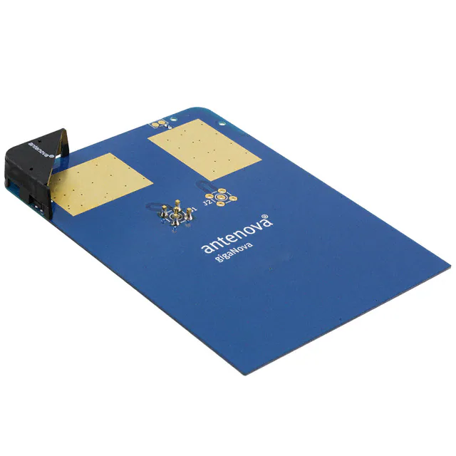


 工商网监
湘ICP备2023018690号
工商网监
湘ICP备2023018690号
