RoHS Compliant
Touch Switch Module Specification
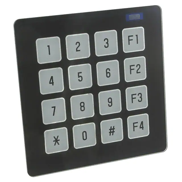
Model: TKU016CT-A100
Specification No.:
DS-1980-0001-04
Date of Issue:
September 29, 2016 (00)
Revision:
October 4, 2016 (01)
October 31, 2016 (02)
February 3, 2017 (03)
February 6, 2017 (04)
Published by
NORITAKE ITRON CORP. / Japan
http://www.noritake-itron.jp
This specification is subject to change without prior notice.
This product complies with RoHS Directive
Please contact our sales consultant for details and to confirm the current status
�TKU016CT-A100
Contents
1
2
Touch Switch Module Handling and Usage Precautions ............................................................................................. 4
General Description..................................................................................................................................................... 6
2.1
Scope ............................................................................................................................................................. 6
2.2
Construction ................................................................................................................................................... 6
2.3
Outline ............................................................................................................................................................ 6
2.4
Weight ............................................................................................................................................................ 6
2.5
Block Diagram ................................................................................................................................................ 7
3
Electrical specifications ............................................................................................................................................... 8
3.1
Absolute Maximum Ratings ............................................................................................................................ 8
3.2
Electrical ratings ............................................................................................................................................. 8
3.3
Electrical Characteristics ................................................................................................................................ 8
3.4
General-purpose Port ..................................................................................................................................... 9
4
Optical Specifications (Backlight LED) ...................................................................................................................... 10
5
Environmental Specifications .................................................................................................................................... 10
6
Touch Switch Specification ........................................................................................................................................ 10
6.1
General Description...................................................................................................................................... 10
6.2
Basic Operation ............................................................................................................................................ 10
6.3
Cautions ....................................................................................................................................................... 11
6.4
Touch-Switch control .................................................................................................................................... 12
6.4.1
Basic function............................................................................................................................................. 12
6.4.2
Auto-calibration .......................................................................................................................................... 12
6.4.3
Touch-Switch control commands ............................................................................................................... 13
7
Interface .................................................................................................................................................................... 14
7.1
Type of interface ........................................................................................................................................... 14
7.2
Basic function ............................................................................................................................................... 14
7.2.1
Asynchronous serial interface .................................................................................................................... 14
7.2.2
SPI ............................................................................................................................................................. 15
2
7.2.3
I C interface ............................................................................................................................................... 17
7.3
Key Scan interface ....................................................................................................................................... 19
7.4
Reset timing ................................................................................................................................................. 20
8
Function .................................................................................................................................................................... 21
8.1
Commands ................................................................................................................................................... 21
8.1.1
All Touch-Switch Status Read [Only valid in Manual transmit mode] ......................................................... 21
8.1.2
Individual Touch-Switch Status Read [Only valid in Manual transmit mode] .............................................. 21
8.1.3
Touch-Level Order Switch Reading............................................................................................................ 21
8.1.4
All Touch-Switch Count-Level Read ........................................................................................................... 22
8.1.5
All Touch-Switch Touch-Level Read ........................................................................................................... 22
8.1.6
Touch-Switch Status read Mode Setting .................................................................................................... 22
8.1.7
All LED Control .......................................................................................................................................... 23
8.1.8
Individual LED Control ............................................................................................................................... 25
8.1.9
Fixed Buzzer Sound Output Control .......................................................................................................... 25
8.1.10
Buzzer Sound Pitch Control ....................................................................................................................... 26
8.1.11
Transmit data control ................................................................................................................................. 26
8.1.12
User Setup Mode Start ............................................................................................................................... 26
8.1.13
User Setup Mode End ................................................................................................................................ 27
8.1.14
Status Send 1............................................................................................................................................. 27
8.1.15
Memory SW setting 1 ................................................................................................................................. 27
8.1.16
Memory SW data send 1............................................................................................................................ 27
8.1.17
Status Send 2............................................................................................................................................. 28
8.1.18
Memory Switch Setting 2 ........................................................................................................................... 28
8.1.19
Memory Switch Data Send 2 ...................................................................................................................... 28
8.1.20
General-purpose Port Input........................................................................................................................ 29
8.1.21
General-purpose Port Output ..................................................................................................................... 29
8.1.22
RAM Program Macro Define / Delete ......................................................................................................... 29
8.1.23
Program Macro Execution.......................................................................................................................... 30
8.1.24
FROM Program Macro Define / Delete ...................................................................................................... 30
8.1.25
Touch Parameter Setting ........................................................................................................................... 31
8.1.26
Touch Parameters Send ............................................................................................................................ 32
8.1.27
Touch Parameters Save ............................................................................................................................. 32
8.1.28
Restart Touch Operation ............................................................................................................................ 32
8.2
Initial State .................................................................................................................................................... 32
9
Jumper ...................................................................................................................................................................... 33
9.1
Serial Interface Select .................................................................................................................................. 33
2
9.2
I C Slave Address Select.............................................................................................................................. 33
9.3
Baud Rate Select ......................................................................................................................................... 33
9.4
Operation Mode Select ................................................................................................................................. 33
10
Connector ..................................................................................................................................................... 34
-2-
�TKU016CT-A100
10.1
Serial Interface (CN2) ................................................................................................................................... 34
10.1.1
Asynchronouse Serial Interface mode ....................................................................................................... 34
10.1.2
SPI mode ................................................................................................................................................... 34
10.1.3
I2C mode ................................................................................................................................................... 34
10.2
I/O Port Interface .......................................................................................................................................... 34
10.3
Memory Switch (MSW) ................................................................................................................................. 35
11 Physical Dimensions ................................................................................................................................................. 36
Revision ............................................................................................................................................................................ 37
-3-
�TKU016CT-A100
1
Touch Switch Module Handling and Usage Precautions
Please follow the appropriate product application notes and operation standards for proper usage, safe handling, and
ideal performance.
【The Glass Touch Switch Panel】
In the case of the Touch Switch panel’s edges are
not smooth, it requires careful handling to avoid
injury.
Be careful to avoid breaking the Touch Switch panel as
the resulting sharp glass particles may cause injury.
Do not intentionally destroy the Touch Switch panel.
Do not use with a sharp object as it will scratch and
damage the panel surface.
To clean the surface of the Touch Switch panel, use a
soft cloth and glass cleaner and do not use organic
solvents, acids, or alkalis.
Touch switch panel surface is made only of glass.
For washing, an acidic or slightly alkaline detergent
for glass can also be used.
【Cable Connection】
Do not unplug the power and/or data cables from
the Touch Switch module during operation, this may
result in permanent damage to the module.
Sending input signals to the Touch Switch module
when it is not powered can cause I/O port damage.
It is recommended to use a 30cm or shorter signal
cable to prevent functional failures.
【Electrostatic Charge】
Touch Switch modules need electrostatic-free
packaging and protection from electrostatic charges
during handling and usage.
【Structure】
It is recommended to use UL-grade materials or
components in conjunction with Touch Switch
modules.
Bending and twisting causes stress and may break
the Touch Switch panel and module. Please
minimize chassis movement to accommodate for
the 0.3mm attachment point gap. Failure to do so
may result in panel damage.
Do not apply force to any FPC or cable running from
the control board to the Touch Switch panel.
【Power】
Apply regulated power to the Touch Switch module
within the specified voltages to protect from failures.
The Touch Switch module needs a specific voltage
to operate properly. Please use a reliable power
cable to avoid a voltage decrease. As a safety
measure, a fuse or another type of over-current
protection is recommended.
-4-
Touch Switch modules may draw in-rush current
exceeding twice the typical current at power-on, so
a power supply with sufficient capacity and a
quick-starting power regulator is recommended.
�TKU016CT-A100
【Implementation】
Avoid contact with metal.
If you would like to create a waterproof application,
we recommend that a sturdy and durable sealing
material is used between the panel’s gasket area
and the chassis.
【Storage and Operating Environment】
Please use our Touch Switch modules under the
specified environmental conditions only.
If used in a high temperature environment, there is a
possibility that the Touch Switch panel surface may
be hot.
Salty, sulfuric, and dusty environments may damage
the module even during storage.
There is a risk of burns and other injuries so be
careful when touching the panel.
【Disposal】
Touch Switch uses materials that contain lead (the
RoHS directive exempts these lead compounds for
glass that is used with electronic devices).
When discarding the Touch Switch panel or Touch
Switch module, please adhere to the applicable
laws and regulations.
【Other Precautions】
Although the Touch Switch module is designed to be
tolerant of electrical noise, please place an
emphasis on noise reduction in your circuit design.
Do not reconstruct or repair the Touch Switch
module without our authorization. We cannot assure
the quality or reliability of unauthorized and
reconstructed Touch Switch modules.
We do not authorize the use of any patents that
may be inherent in these specifications.
Whole or partial copying of these specifications is
not permitted without our approval. If necessary,
please ask for our sales consultant for assistance.
This product is not designed for military, aerospace, medical or other life-critical applications.
If you choose to use this product for these applications, please ask us for prior consultation or we cannot accept
responsibility for any problems that may occur.
-5-
�TKU016CT-A100
2
General Description
2.1
Scope
This specification covers the operation and operating requirements of the Touch Switch Module
TKU016CT-A100.
2.2
Construction
The module consists of a mutual-capacitive Touch Switch panel, LEDs for touch switch backlighting,
touch controller, and all necessary control logic.
2.3
Outline
・Power supply:
Single 5VDC power supply
・Interface:
Serial interfaces
2
Asynchronous serial interface/ I C / SPI
Port
General-purpose port / Key scan (selectable)
Read Touch Switch ON/OFF
Touch operation setting
LED setting
Buzzer control
Program Macro function
Miscellaneous
・Function:
・ Applicable Touch Switch Module Reliability Specification
・ Applicable Touch Switch Module Quality Specification
・ Applicable Touch Switch Panel Quality Specification
2.4
Weight
Approximately 78g
-6-
: TT-99-3102
: TT-98-3413
: TT-16-3301
�TKU016CT-A100
2.5
Block Diagram
Number of switches: 16
Number of LED groups:
16
Touch switch panel
Interface connector
Controller
Asyn. mode
RXD, TXD
2
I C mode
SDA, SCL
SPI mode
MOSI,, MISO,
CLK, /CS
/TRDY
/RESET
VCC
GND
Firmware
Internal
circuit
Memory switch
I/O port connector
General port mode
P00-P03
P10-P13
Key Scan mode
KS0-KS3
KD0-KD3
VCC
GND
Touch switch
parameters
SW1
/
LED1
SW5
/
LED5
SW9
/
LED9
SW13
/
LED13
SW2
/
LED2
SW6
/
LED6
SW10
/
LED10
SW14
/
LED14
SW3
/
LED3
SW7
/
LED7
SW11
/
LED11
SW15
/
LED15
SW4
/
LED4
SW8
/
LED8
SW12
/
LED12
SW16
/
LED16
Program macro
Drive circuit
Internal
circuit
Buzzer
Jumper
-7-
�TKU016CT-A100
3
Electrical Specifications
3.1
Absolute Maximum Ratings
Parameter
Symbol
Min.
Typ.
Max.
Unit
Condition
Power Supply Voltage
VCC
-0.3
-
6.0
VDC
-
VIN-S
-0.3
-
6.0
VDC
-0.3
-
3.5
VDC
Vcc > 3.3
-0.3
-
VCC
VDC
Vcc ≤ 3.3
Logic Input Voltage (Pull Up Voltage)
KD0-3, P10-P13
Logic Input Voltage
3.2
-
VIN
Electrical Ratings
3.3
Parameter
Symbol
Min.
Typ.
Max.
Unit
Power Supply Voltage
VCC
4.75
5.0
5.25
VDC
Electrical Characteristics
Measuring Conditions: Ambient temperature = 25 ºC, VCC = 5.0 VDC
Parameter
2
I C interface
I/O
Port
Min.
Max.
Unit
Condition
-
1.0
μADC
VIN=3.3V
-
-0.5
mA
VIN=0V
-
2.0
μADC
VIN=3.3V
"H"
"L"
IIL-1
Logic Input Voltage
/RESET
"H"
IIH-2
"L"
IIL-2
-
-
-0.5
mA
VIN=0V
Logic Input Voltage
SDA,SCL
"H"
VIH-1
2.7
-
-
VDC
-
"L"
VIL-1
-
-
0.6
VDC
-
Logic Input Voltage
/RESET
"H"
VIH-2
2.7
-
-
VDC
-
"L"
VIL-2
-
-
0.2
VDC
-
"L"
VOL-1
-
-
0.8
VDC
IOL= 2mA
Logic Output Voltage
/TRDY
"H"
VOH-2
2.4
-
-
VDC
IOH=-0.5mA
"L"
VOL-2
-
-
0.9
VDC
IOL= 1.0mA
Logic Input Current
RXD,MOSI,SCK,/CS
"H"
IIH-3
-
-
1.0
μADC
VIN=3.3V
"L"
IIL-3
-
-
-0.5
mADC
VIN=0V
Logic Input Current
/RESET
"H"
IIH-4
-
-
2.0
μADC
VIN=3.3V
"L"
IIL-4
-
-
-0.5
mADC
VIN=0V
Logic Input Voltage
RXD,MOSI,SCK,/CS
"H"
VIH-3
2.7
-
-
VDC
-
"L"
VIL-3
-
-
0.6
VDC
-
Logic Input Voltage
/RESET
"H"
VIH-4
2.7
-
-
VDC
-
"L"
VIL-4
-
-
0.2
VDC
-
Logic Output Voltage
TXD,MISO,/TRDY
"H"
VOH-3
2.4
-
-
VDC
IOH= -0.5mA
"L"
VOL-3
-
-
0.9
VDC
IOL= 1.0mA
Logic Input Current
KS0-KS3, P00-P03
"H"
IIH-5
-
-
1.0
μADC
VIN=3.3V
"L"
IIL-5
-
-
-0.5
mADC
VIN=0V
Logic Input Voltage
KS0-KS3, P00-P03
"H"
VIH-5
2.7
-
-
VDC
-
"L"
VIL-5
-
-
0.6
VDC
-
Logic Input Voltage
KD0-KD3, P10-P13
"H"
VOH-4
"L"
VOL-4
Output allowable current
KD0-KD3, P10-P13 (per pin)
"H"
IiOH-1
"L"
Internal Pull-up Resistor
RXD,TXD,MOSI,MISO,SCK,
/CS,SDA,SCL,
/TRDY,/RESET, KS0-KS3, P00-P03
IIH-1
Typ.
Logic Input Voltage
SDA,SCL
Logic Output Voltage
SDA,SCL
Other
interfaces
Symbol
-
Open Collector
-
-
IiOL-1
-
-
3
mADC
-
Rp
-
10
-
kΩ
-
-8-
0.5
VDC
Open Collector
IOL = 1mA
�TKU016CT-A100
Parameter
Symbol
Min.
Typ.
Max.
Unit
Power Supply Current 1
ICC-1
-
520
610
mADC
Power Supply Current 2
ICC-2
-
260
310
mADC
Power Supply Current 3
ICC-3
30
45
mADC
2.6
3.1
W
Power Consumption
Condition
All LED ON (Brightness level 100%)
Buzzer ON
All LED ON (Brightness level 50%)
Buzzer OFF
All LED OFF
Buzzer OFF
All LED ON (Brightness level 100%)
Buzzer ON
・A quick-rise type power supply (


 工商网监
湘ICP备2023018690号
工商网监
湘ICP备2023018690号
