Adafruit TB6612 1.2A DC/Stepper Motor
Driver Breakout Board
Created by lady ada
https://learn.adafruit.com/adafruit-tb6612-h-bridge-dc-stepper-motor-driver-breakout
Last updated on 2021-11-15 06:26:14 PM EST
©Adafruit Industries
Page 1 of 19
�Table of Contents
Overview
3
Pinouts
5
• Power Pins
• Signal in Pins
• Motor Out Pins
6
6
6
Assembly
7
• Prepare the header strip:
• Add the breakout board:
• And Solder!
7
7
8
Arduino Use: Stepper Motors
9
• Wiring
• Software
9
10
Python & CircuitPython: Stepper Motors
11
•
•
•
•
•
11
13
14
15
15
CircuitPython Microcontroller Wiring
Python Computer Wiring
CircuitPython Installation of Motor Library
Python Installation of Motor Library
CircuitPython & Python Usage
Python Docs
17
Downloads
17
• Files
• Schematic
• Fabrication print
17
18
18
©Adafruit Industries
Page 2 of 19
�Overview
Fire four solenoids, spin two DC motors or step one bi-polar or uni-polar stepper with
1.2A per channel using the TB6612. These are perhaps better known as "the drivers in
our assembled Adafruit Motorshield (http://adafru.it/1438) or Motor HAT (https://
adafru.it/eRq)" We really like these dual H-bridges, so if you want to control motors
without a shield or HAT these are easy to include on any solderless breadboard or
perma-proto.
©Adafruit Industries
Page 3 of 19
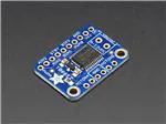
�We solder on TB6612 onto a breakout board for you here, with a polarity protection
FET on the motor voltage input and a pullup on the "standby" enable pin. Each
breakout chip contains two full H-bridges (four half H-bridges). That means you can
drive four solenoids, two DC motors bi-directionally, or one stepper motor. Just make
sure they're good for 1.2 Amp or less of current, since that's the limit of this chip. They
do handle a peak of 3A but that's just for a short amount of time, about 20
milliseconds. What we like most about this particular driver is that it comes with built
in kick-back diodes internally so you dont have to worry about the inductive kick
damaging your project or driver!
There's two digital inputs per H-bridge (one for each half of the bridge) as well as a
PWM input per driver so you can control motor speed. Runs at 2.7V-5V logic. The
motor voltage is separate from the logic voltage. Good for motor voltages from 4.5V
up to 13.5V! This wont work well for 3V motors.
©Adafruit Industries
Page 4 of 19
�Comes as one assembled and tested breakout plus a small strip of header. You'll need
to do some light soldering to attach the header onto the breakout PCB. Arduino,
motors, and power supply not included.
Pinouts
This motor driver is a fairly simple breakout of the TB6612 motor chip, so do check
out the datasheet for the TB6612 for any details you need about pin voltage limits,
capacitance, etc! (https://adafru.it/emK)
©Adafruit Industries
Page 5 of 19
�Power Pins
• Vmotor - This is the voltage for the motors, not for the logic level. Keep this
voltage between 4.5V and 13.5V. This power supply will get noisy so if you have
a system with analog readings or RF other noise-sensitive parts, you may need
to keep the power supplies seperate (or filtered!)
• Vcc - this is the voltage for the logic levels. Set to the voltage logic you'll be
using on your microcontroller. E.g. for Arduinos, 5V is probably what you want.
Can be 2.7V to 5.5V so good for 3V or 5V logic
• GND - This is the shared logic and motor ground. All grounds are connected
Signal in Pins
These are all 'Vcc logic level' inputs
• INA1, INA2 - these are the two inputs to the Motor A H-bridges
• PWMA - this is the PWM input for the Motor A H-bridges, if you dont need PWM
control, connect this to logic high.
• INB1, INB2 - these are the two inputs to the Motor B H-bridges
• PWMB - this is the PWM input for the Motor B H-bridges, if you dont need PWM
control, connect this to logic high.
• STBY - this is the standby pin for quickly disabling both motors, pulled up to Vcc
thru a 10K resistor. Connect to ground to disable.
Motor Out Pins
These are 'Vmotor level' power outputs
• Motor A - these are the two outputs for motor A, controlled by INA1, INA2 and
PWMA
• Motor B - these are the two outputs for motor B, controlled by INB1, INB2 and
PWMB
©Adafruit Industries
Page 6 of 19
�Assembly
Prepare the header strip:
Cut the strip to length if necessary. It will
be easier to solder if you insert it into a
breadboard - long pins down
Add the breakout board:
Place the breakout board over the pins
so that the short pins poke through the
breakout pads
©Adafruit Industries
Page 7 of 19
�And Solder!
Be sure to solder all pins for reliable
electrical contact.
(For tips on soldering, be sure to check
out our Guide to Excellent
Soldering (https://adafru.it/aTk)).
©Adafruit Industries
Page 8 of 19
�Arduino Use: Stepper Motors
In this example we'll wire up and use a bi-polar stepper motor with recommended 12V
motor voltage, and 200 steps per rotation.
Wiring
We'll wire it to a Metro, but you can use any microcontroller you like!
Connect:
• Vmotor to 12V (red wire)
• Vcc to 5V (orange wire)
• GND to ground
• AIN2 to Digital 4
• AIN1 to Digital 5
• BIN1 to Digital 6
• BIN2 to Digital 7
• PWMA and PWMB to Vcc (orange wire)
Then hook one stepper motor coil to Motor A (red and yellow) and the second coil to
Motor B (green and gray/brown). If you have another motor, you'll need to experiment
a little to figure out which wires are which coil. Check any documentation you have!
You can use a multimeter to measure between wires, the ones with a small resistance
©Adafruit Industries
Page 9 of 19
�between them are a pair to a coil, for example. If the motor is vibrating but not
spinning, check all wires are connected and try flipping around a pair or rechecking
the wire pairs.
If you have a unipolar motor, there will be a 5th or 6th wire that is the 'common' wire.
Connect these wires to the GND pins in between the Motor A and B outputs on the
breakout.
Software
We'll use the built-in Arduino Stepper library (https://adafru.it/eRw), but you can
manually toggle the AIN1/AIN2/BIN1/BIN2 pins with your own favorite microcontroller
setup
#include <Stepper.h>
// change this to the number of steps on your motor
#define STEPS 200
// create an instance of the stepper class, specifying
// the number of steps of the motor and the pins it's
// attached to
Stepper stepper(STEPS, 4, 5, 6, 7);
void setup()
{
Serial.begin(9600);
Serial.println("Stepper test!");
// set the speed of the motor to 30 RPMs
stepper.setSpeed(60);
}
©Adafruit Industries
Page 10 of 19
�void loop()
{
Serial.println("Forward");
stepper.step(STEPS);
Serial.println("Backward");
stepper.step(-STEPS);
}
Basically after you make the Stepper object with the 4 control pins, you can set the
rotational speed (in RPM) with setSpeed(rpm) and then step forward or backwards
with .step(steps) where steps is positive for 'forward' and negative for 'backward'
For more details, check out the Stepper library (https://adafru.it/eRw)
Python & CircuitPython: Stepper Motors
It's easy to use the DRV8833 DC/Stepper Motor Driver or the TB6612 DC/Stepper
Motor Driver breakouts with CircuitPython and Python using the Adafruit
CircuitPython Motor (https://adafru.it/BCK) library to control stepper motors. We'll
show you how to wire them up and use the library to control a stepper motor. The
code is the same for both breakouts, however the pinouts on each breakout are
slightly different.
You can use this breakout with any CircuitPython microcontroller board or with a
computer that has GPIO and Python thanks to Adafruit_Blinka, our CircuitPython-forPython compatibility library (https://adafru.it/BSN).
CircuitPython Microcontroller Wiring
You can use any CircuitPython microcontroller board, but bear in mind that motors
require external power to run. The Metro M0 and M4 have a convenient pin available
for providing sufficient power, so this example will use the Metro M4.
For the VIN pin on the Metro to provide sufficient power to the stepper motor,
you must plug in a 9V power supply into the barrel jack built into the Metro, and
ensure the switch is "on".
We're using this stepper motor (https://adafru.it/BxE) with this 9V power supply (https:
//adafru.it/dO6). With the Metro board, the 9V power supply will power both the Metro
and the stepper motor.
Connect a Metro M4, the DRV8833 breakout and a stepper motor as follows:
©Adafruit Industries
Page 11 of 19
�• Board VM to Metro VIN
• Board GND to Metro GND
• Board SLP to Metro 5V
• Board AIN1 to Metro D9
• Board AIN2 to Metro D10
• Board BIN1 to Metro D11
• Board BIN2 to Metro D12
• Board AOUT (1 and 2) to stepper
coil (red and yellow stepper wires)
• Board BOUT (1 and 2) to stepper
coil (green and grey stepper wires)
• 9V power supply to barrel jack on
Metro
For use with the TB6612, connect the Metro M4, breakout and stepper motor as
follows:
• Board VM to Metro VIN
• Board VCC to breadboard power
rail
• Board GND to Metro GND
• Board PWMB to breadboard power
rail
• Board BIN2 to Metro D12
• Board BIN1 to Metro D11
• Board AIN1 to Metro D9
• Board AIN2 to Metro D10
• Board PWMA to breadboard power
rail
• Breadboard power rail to Metro 5V
• Board MOTORA (two pins) to
stepper coil (red and yellow stepper
wires)
• Board MOTORB (two pins) to
stepper coil (green and grey
stepper wires)
• 9V power supply to barrel jack on
Metro
©Adafruit Industries
Page 12 of 19
�Python Computer Wiring
Since there's dozens of Linux computers/boards you can use we will show wiring for
Raspberry Pi. For other platforms, please visit the guide for CircuitPython on Linux to
see whether your platform is supported (https://adafru.it/BSN).
The Raspberry Pi will not provide sufficient power to run the stepper motor. You
must power the driver board externally with a 9V power supply for the motor to
work.
We're using this stepper motor (https://adafru.it/BxE), and powering the driver board
with this 9V power supply (https://adafru.it/dO6). With the Raspberry Pi, you'll need a
separate 5V power supply for the Pi (on USB as normal).
Here's the Raspberry Pi, breakout and stepper motor wired up to the DRV8833:
• Board VM to positive terminal on
barrel jack
• Board GND to negative terminal on
barrel jack
• Barrel jack to 9V power supply
• Board GND to Pi GND
• Board SLP to Pi 3.3V
• Board AIN1 to Pi D19
• Board AIN2 to Pi D26
• Board BIN1 to Pi D20
• Board BIN2 to Pi D21
• Board AOUT (1 and 2) to stepper
coil (red and yellow stepper wires)
• Board BOUT (1 and 2) to stepper
coil (green and grey stepper wires)
And, the Raspberry Pi, breakout and stepper motor wired up to the TB6612:
©Adafruit Industries
Page 13 of 19
�• Board VM to positive terminal on
barrel jack
• Board GND to negative terminal on
barrel jack
• Barrel jack to 9V power supply
• Board VCC to breadboard power
rail
• Board GND to Pi GND
• Board PWMB to breadboard power
rail
• Board BIN2 to Pi D21
• Board BIN1 to Pi D20
• Board AIN1 to Pi D19
• Board AIN2 to Pi D26
• Board PWMA to breadboard power
rail
• Breadboard power rail to Pi 3.3V
• Board MOTORA (two pins) to
stepper coil (red and yellow stepper
wires)
• Board MOTORB (two pins) to
stepper coil (green and grey
stepper wires)
CircuitPython Installation of Motor Library
Next you'll need to install the Adafruit CircuitPython Motor (https://adafru.it/BCK) libra
ry on your CircuitPython board.
First make sure you are running the latest version of Adafruit CircuitPython (https://
adafru.it/Em8) for your board.
Next you'll need to install the necessary library to use the hardware--carefully follow
the steps to find and install the library from Adafruit's CircuitPython library bundle (htt
ps://adafru.it/ENC). Our introduction guide has a great page on how to install
modules from the library bundle (https://adafru.it/ABU).
©Adafruit Industries
Page 14 of 19
�You'll need to manually install the
necessary library from the bundle:
• adafruit_motor
Before continuing make sure your
board's lib folder or root filesystem has
the adafruit_motor folder copied over.
Python Installation of Motor Library
You'll need to install the Adafruit_Blinka library that provides the CircuitPython
support in Python. This may also require enabling I2C on your platform and verifying
you are running Python 3. Since each platform is a little different, and Linux changes
often, please visit the CircuitPython on Linux guide to get your computer ready (https
://adafru.it/BSN)!
Once that's done, from your command line run the following command:
• pip3 install adafruit-circuitpython-motor
If your default Python is version 3 you may need to run 'pip' instead. Just make sure
you aren't trying to use CircuitPython on Python 2.x, it isn't supported!
CircuitPython & Python Usage
To demonstrate the usage of the DRV8833 and the TB6612, we'll use a complete
code example to control a stepper motor. Code is the same for both boards.
Save the following code to your CIRCUITPY drive as code.py:
# SPDX-FileCopyrightText: 2021 ladyada for Adafruit Industries
# SPDX-License-Identifier: MIT
# Use this example for digital pin control of an H-bridge driver
# like a DRV8833, TB6612 or L298N.
import time
import board
import digitalio
©Adafruit Industries
Page 15 of 19
�from adafruit_motor import stepper
DELAY = 0.01
STEPS = 200
# You can use any available GPIO pin on both a microcontroller and a Raspberry Pi.
# The following pins are simply a suggestion. If you use different pins, update
# the following code to use your chosen pins.
# To use with CircuitPython and a microcontroller:
coils = (
digitalio.DigitalInOut(board.D9), # A1
digitalio.DigitalInOut(board.D10), # A2
digitalio.DigitalInOut(board.D11), # B1
digitalio.DigitalInOut(board.D12), # B2
)
# To use with a Raspberry Pi:
# coils = (
#
digitalio.DigitalInOut(board.D19),
#
digitalio.DigitalInOut(board.D26),
#
digitalio.DigitalInOut(board.D20),
#
digitalio.DigitalInOut(board.D21),
# )
#
#
#
#
A1
A2
B1
B2
for coil in coils:
coil.direction = digitalio.Direction.OUTPUT
motor = stepper.StepperMotor(coils[0], coils[1], coils[2], coils[3],
microsteps=None)
for step in range(STEPS):
motor.onestep()
time.sleep(DELAY)
for step in range(STEPS):
motor.onestep(direction=stepper.BACKWARD)
time.sleep(DELAY)
for step in range(STEPS):
motor.onestep(style=stepper.DOUBLE)
time.sleep(DELAY)
for step in range(STEPS):
motor.onestep(direction=stepper.BACKWARD, style=stepper.DOUBLE)
time.sleep(DELAY)
for step in range(STEPS):
motor.onestep(style=stepper.INTERLEAVE)
time.sleep(DELAY)
for step in range(STEPS):
motor.onestep(direction=stepper.BACKWARD, style=stepper.INTERLEAVE)
time.sleep(DELAY)
motor.release()
Once saved, watch your stepper motor move!
Let's take a look at the code. First, import the necessary libraries. Set the DELAY in
seconds for the time between each motor control statement, and the number of STE
PS used in each control block.
©Adafruit Industries
Page 16 of 19
�Next, set up the pins used by the driver board. If you followed the diagrams above,
these will already be correct. If you did not, change these to match the pins you used.
If you're using CircuitPython on a microcontroller, no changes are necessary. If you're
using a Raspberry Pi with Adafruit Blinka, then you need to comment out the
microcontroller pins, and uncomment the Raspberry Pi pins.
Then, set all the pins to OUTPUT , and instantiate motor with each of the four coils.
Now you can begin controlling the motor using the many options available in the
Adafruit CircuitPython Motor library. You can check out the documentation (https://
adafru.it/BNE) for details.
That's all there is to controlling a stepper motor with a DRV8833 or the TB6612!
Python Docs
Python Docs (https://adafru.it/C5o)
Downloads
Files
• This motor driver is a fairly simple breakout of the TB6612 motor chip, so do
check out the datasheet for the TB6612 for any details you need about pin
voltage limits, capacitance, etc! (https://adafru.it/emK)
• Fritzing object in the Adafruit Fritzing Library (https://adafru.it/aP3)
• EagleCAD PCB files (https://adafru.it/rF1)
©Adafruit Industries
Page 17 of 19
�Schematic
Fabrication print
Dimensions in inches
©Adafruit Industries
Page 18 of 19
�©Adafruit Industries
Page 19 of 19
�


 工商网监
湘ICP备2023018690号
工商网监
湘ICP备2023018690号

