Adafruit TPL5110 Power Timer Breakout
Created by lady ada
https://learn.adafruit.com/adafruit-tpl5110-power-timer-breakout
Last updated on 2021-11-15 06:53:17 PM EST
©Adafruit Industries
Page 1 of 17
�Table of Contents
Overview
3
Pinouts
5
• Power Pins
• Control Pins
6
6
Assembly
7
• Prepare the header strip:
• Add the breakout board and Solder!
8
8
Usage
9
•
•
•
•
10
13
15
15
Notes on the Delay Pin
ESP8266 Feather Example
Video Example
Handy Accessories
Downloads
• Files
• Schematic and Fabrication Print
©Adafruit Industries
16
16
17
Page 2 of 17
�Overview
With some development boards, low power usage is an afterthought. Especially when
price and usability is the main selling point. So what should you do when it's time to
turn around and make that project of yours run on a battery or solar? Sure you could
try to hot-air that regulator off, or you could jerry-rig a relay. Or, use a 555? Ugh, the
options aren't that great.
The Adafruit TPL5110 Power Timer is a stand-alone breakout that will turn any
electronics into low-power electronics! It will take care of turning your project on/off
using a built in timer that can vary from once-every 100ms up to once every two
hours. Basically, the TPL will turn on periodically, adjustable by potentiometer or
resistor, and turn on your project's power. It will then wait until a signal is received
from the project to tell the TPL that it can safely turn off the power. If the TPL does not
receive a signal by the set time-out, it will reset the device like a watchdog timer.
©Adafruit Industries
Page 3 of 17
�Usage is easy. First, disconnect from power and set your desired delay by adjusting
the on-board trim pot: all the way to the left is once-per-100ms an all the way to the
right is once-every-2-hours. Then, connect VDD up to your 3-5V power supply and
then your project's power-in to the Drive pin. Finally, select a signal pin from your
project to the Done pin. In your project's code or design, just make sure that it sets
the Done pin high once it is completed with its task. That's it!
While the TPL5110 is running (but the remainder of the project is de-powered) the
current draw is about 20uA (according to our Monsoon Power Meter)
If you want to turn the device on by hand, you can also activate the TPL by pressing
the onboard tactile switch (or wire your own switch to the Delay pin) See? Your power
problems just got solved!
©Adafruit Industries
Page 4 of 17
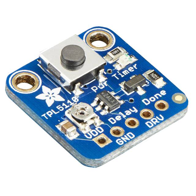
�Comes as a fully assembled breakout board with a TPL5110 chip, all components onboard, and some header. A little light soldering is required to put it together for
breadboard use.
Pinouts
There's a lot going on with this compact breakout, and many ways to do one thing so
reviewing the pinouts is a really good idea!
©Adafruit Industries
Page 5 of 17
�Power Pins
• VDD - this is the power input pin for both the TPL5110 chip and the device you
want to control. Make sure this is always connected and powered. This has to be
3-5VDC so don't give it 12VDC power.
• GND - this is shared ground for power and signal.
Control Pins
• Delay - this is the delay control pin. By adjusting the resistance (not voltage!)
connected to this pin through to ground, you can change the delay between
powerings. By default this is connected to the onboard trim potentiometer.
However, you can cut the trace on the back and then connect your own resistor
between Delay and GND. Also, if this pin is connected directly to VDD (say
through a switch) it will activate the output instantly.
Note this pin is not continuously sampled. You need to remove and re-apply
power once you change the resistance!
• DRV - this is the Drive output pin, the TPL5110 will power this pin with the same
voltage as from VDD when the timer activates
• Done - This is the signal pin from the driven electronics back to the TPL5110 to
let it know that it is 'done' with whatever it had to do, and the TPL5110 can turn it
off
There is also an 'active' LED in the top right. This will let you know when the DRV pin
is powered. It does draw some current so if you need ultra-low current draw, cut the
trace behind the PCB!
©Adafruit Industries
Page 6 of 17
�Assembly
This page shows the TPL5110 but the TPL5111 procedure is identical!
©Adafruit Industries
Page 7 of 17
�Prepare the header strip:
Cut the strip to length if necessary. It will
be easier to solder if you insert it into a
breadboard - long pins down
Add the breakout board
and Solder!
Place the breakout board over the pins
so that the short pins poke through the
breakout pads
Be sure to solder all 5 pins for reliable
electrical contact.
(For tips on soldering, be sure to check
out our Guide to Excellent
Soldering (https://adafru.it/aTk)).
©Adafruit Industries
Page 8 of 17
�You're done! Check your solder joints
visually and continue onto the next steps
Usage
Using the TPL5110 isn't too hard but there's a few things to watch out for. First up, do
not give it 9V power, use 3-5V only!
Make sure to provide the power to the VDD and GND pins. Then connect your project
to the DRV and GND pin. Use a DONE pin from your microcontroller to signal when
the TPL can disable power: when the DONE pin goes from low to high, that will turn
off the TPL's power transistor.
In this project I'm using A3 as the DONE signal pin. You can use any pin you like as
long as the wiring matches your sketch. The pin is lightly pulled down so just set to an
Output and High when you're done!
If the TPL doesn't get a DONE signal, it will reset the board with a short ENABLE
toggle when the timeout is reached (e.g. before the next cycle)
©Adafruit Industries
Page 9 of 17
�Notes on the Delay Pin
The delay pin is a little more complicated than you may first think!
• First, do not connect a voltage here, instead it uses a resistor to determine the
delay timing.
• Second, it does not continuously sample the resistor, it only does it once when
power is applied. So set the delay you want, then power up the breakout.
• Third, you can instantly turn on the project by connecting Delay to VDD. By
default we have a pushbutton on board, you can connect your own button if you
like
• Fourth, the resistance is not linear with the time delay, rather there is a complex
algorithm to set the time based on resistance. You can check the datasheet for
the precise calculation, or use this rough table:
1 Seconds
5.2 KΩ
2 Seconds
6.79 kΩ
3 Seconds
7.64 kΩ
4 Seconds
8.3 kΩ
5 Seconds
8.85 kΩ
6 Seconds
9.26 kΩ
7 Seconds
9.71 kΩ
8 Seconds
10.18 kΩ
©Adafruit Industries
Page 10 of 17
�9 Seconds
10.68 kΩ
10 Seconds
11.2 kΩ
20 Seconds
14.41 kΩ
30 Seconds
16.78 kΩ
40 Seconds
18.75 kΩ
50 Seconds
20.047 kΩ
1 Minute
22.02 kΩ
2 Minutes
29.35 kΩ
3 Minutes
34.73 kΩ
4 Minutes
39.11 kΩ
5 Minutes
42.90 kΩ
6 Minutes
46.29 kΩ
7 Minutes
49.38 kΩ
8 Minutes
52.24 kΩ
©Adafruit Industries
Page 11 of 17
�9 Minutes
54.92 kΩ
10 Minutes
57.44 kΩ
20 Minutes
77.57 kΩ
30 Minutes
92.43 kΩ
40 Minutes
104.67 kΩ
50 Minutes
115.33 kΩ
1 Hour
124.91 kΩ
1 Hour 30 Minutes
149.39 kΩ
2 Hours
170 kΩ
Given that we put a 200 kΩ trimpot on the board, you may find it difficult to get
precise timing if you need short delays. In that case, you can use any resistor you
want. First, cut the trace on the back of the PCB
©Adafruit Industries
Page 12 of 17
�Then install your desired resistor:
Don't forget to hard-reset the full setup!
ESP8266 Feather Example
ESP8266's are a little finicky and may need some tweaks to get working. Note that
some pins have special purpose so are not suitable for a DONE pin. Here's a demo of
an ESP8266 Feather with a NeoPixel ring. We power from a microUSB cable through
a breakout adapter. The USB power goes through the TPL5110 to the power rail. We
added a 47uF capacitor to stabilize the power rail.
For the code, we toggle the DONE pin high and low forever to make sure it gets
'caught' by the TPL (it may not be necessary but it doesn't hurt!)
©Adafruit Industries
Page 13 of 17
�While we've used this breakout with Huzzah ESP8266 Feather successfully other people have said it doesn't work for them. So use with ESP8266 is not
guaranteed.
#include
#if defined(ESP8266)
#define NEOPIX
4
#define DONEPIN 5
#else
#include
#define NEOPIX
13
#define DONEPIN 12
#endif
Adafruit_NeoPixel strip = Adafruit_NeoPixel(12, NEOPIX, NEO_GRB + NEO_KHZ800);
void setup() {
pinMode(DONEPIN, OUTPUT);
digitalWrite(DONEPIN, LOW);
Serial.begin(115200);
Serial.println("Light up NeoPixels!");
strip.begin();
strip.show(); // Initialize all pixels to 'off'
strip.setBrightness(20);
}
void loop() {
rainbowCycle(5);
Serial.println("NeoPixels done, sleeping");
// toggle DONE so TPL knows to cut power!
while (1) {
digitalWrite(DONEPIN, HIGH);
delay(1);
digitalWrite(DONEPIN, LOW);
delay(1);
}
Serial.println("Awake!");
}
// Slightly different, this makes the rainbow equally distributed throughout
void rainbowCycle(uint8_t wait) {
©Adafruit Industries
Page 14 of 17
�uint16_t i, j;
for(j=0; j


 工商网监
湘ICP备2023018690号
工商网监
湘ICP备2023018690号
