D
GN
C
VC
T
OU
DS GUIDE
Your guide to the SparkFun Digital Sandbox
Version 1.0
�Index
Welcome to the Digital Sandbox!
When partnered with the Digital Sandbox, this guide helps to introduce the fundamental concepts
of programming and electronics. Using ArduBlock – a simple, graphical version of the popular
Arduino programming language – you will program 13 experiments that progressively explore
subjects like digital inputs, analog outputs, serial communication and more. The experiments are
project-based, and are built to inspire inventions such as reaction-testing games, automatic
night lights, adjustable volume meters and more.
2
The Anatomy of the Digital Sandbox
4
Digital Sandbox Baseplate Setup
5
Setting up Arduino and ArduBlock
7
Experiment 0: Setup, Loop, and Blink
11
Experiment 1: Exploring Blink
15
Experiment 2: Multi-Blink
19
Experiment 3: Dimming (the Hard Way)
23
Experiment 4: Dimming (the Easy Way)
27
Experiment 5: Color Mixing
31
Experiment 6: Number Storage with Variables
35
Experiment 7: If This, Then That
39
Experiment 8: The Reaction Tester
43
Experiment 9: Serial Calculator
47
Experiment 10: Do the Analog Slide
51
Experiment 11: Automatic Night Light
55
Experiment 12: Thermal Alert!
59
Experiment 13: Sound Detecting
Bonus add-on experiments (parts not included):
63
Experiment 14: Opto-Theremin
69
Experiment 15: Serial Motoring
75
Experiment 16: Servo Sweeper
Page 1
�The Anatomy of the Digital Sandbox
1
USB Mini-B Connector
Used to connect to a computer
JST Right-Angle
Connector
2
Used to supply power to the board
Slide Switch for
Charging
3
Used to charge a lithium polymer battery
that is plugged into the two-pin JST
connector, while the Digital Sandbox
is connected to a computer and the slide
switch is in the "ON" position
4
Reset Button
This is a way to manually reset your
Digital Sandbox, which will restart your
code from the beginning.
5
Slide Switch (Pin D2)
On or off slide switch.
6
LEDs (Pins D4-D8)
Use one or all of the LEDs (light-emitting
diodes) to light up your project!
7
LED (Pin 13)
Incorporate this into your sketch to show
whether your program is running properly.
Temperature Sensor
(Pin A0)
8
Measures ambient temperature
9
Light Sensor (Pin A1)
Measures the amount of light hitting
the sensor
Page 2
10
RGB LED (Pins D9-D11)
RGB (red-green-blue) LEDs have three
different color-emitting diodes that can be
combined to create many colors.
Slide Potentiometer
(Pin A3)
11
Change the values by sliding it back
and forth.
12
Microphone (Pin A2)
Measures how loud something is
13
Push Button (Pin D12)
A button is a digital input. It can be
either “on” or “off.”
14
Add-on Header (Pin D3)
Three-pin header for add-ons. Example
add-ons are servos, motors and buzzers.
�The Anatomy of the Digital Sandbox
1
2
12
9
3
8
4
7
6
5
10
13
11
14
GND
VCC
OUT
Page 3
�Digital Sandbox Baseplate Setup
OUT
VCC
GND
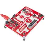
Secure the Digital Sandbox board to the baseplate
The Digital Sandbox board can be attached with the included Phillips-head screws for easy
removal later.
Page 4
�Setting up Arduino and ArduBlock
Download the Arduino/ArduBlock Combo
Arduino and ArduBlock are available for all popular operating systems. To download Arduino
and ArduBlock, please go to:
www.sparkfun.com/digitalsandbox
Make sure you grab the version that matches your operating system.
The Arduino software comes packaged in an archived .ZIP format. Once you’ve downloaded
the ZIP file, you’ll need to extract it.
Mac users: Move the Arduino application into the Applications folder. Move the Digital
Sandbox Examples folder to your preferred location.
Windows users: Move the Arduino folder to your preferred location.
Install Drivers
Once you have downloaded and extracted the Arduino software, connect the Digital Sandbox
to your computer.
OUT
VCC
GND
Once the board is connected, you will need to install drivers. For instructions specific to your
operating system, please go to:
www.sparkfun.com/ftdi
Open Arduino and ArduBlock
ArduBlock is an add-on that exists inside the Arduino software. To open it, first open the Arduino
IDE. Windows users should run Arduino.exe; Mac users can run the Arduino application.
Page 5
�Setting up Arduino and ArduBlock
Let’s do some preparation before opening ArduBlock. First, go to the Tools menu, hover over
Board and select Digital Sandbox.
File
Edit Sketch Tools
Help
Auto Format
Archive Sketch
Fix Encoding &
Reload
Serial Monitor
sketch_01 ArduBlock
Digital Sandbox
Arduino Duemilanove w/ ATmega328]
Arduino Diecimila or Duemilanove w/ ATmega168
Programmer
Arduino Nano w/ ATmega328
Burn
Bootloader
ATmega168
Next, go back to the Tools menu, hover overArduino
SerialNano
Portw/and
select the serial port number
Arduino Mega 2560 or Mega ADK
that matches your Sandbox board.
Arduino Mega (ATmega1280)
Arduino Mini
w/ATmega168
Window users: This is likely to be COM3 or Arduino
higherMini
(COM1
and COM2 are usually reserved
Arduino Ethernet
for hardware serial ports). To find out, you can
disconnect
your
Sandbox and re-open the
Arduino Fio
Arduino
BT w/ ATmega328
menu; the entry that disappears should be the
Sandbox.
Reconnect the board and select that
Arduino BT w/ATmega168
serial port.
LilyPad Arduino w/ ATmega328
LilyPad Arduino w/ ATmega168
Arduino with
Pro or /dev/tty.usbmodem
Pro Mini (5V, 16 MHz) w/ATmega328
Mac users: On the Mac, this should be something
or
Arduino Pro or Pro Mini (5V, 16 MHz) w/ATmega168
/dev/tty.usbserial in it.
Arduino Pro or Pro Mini (3.3V, 8 MHz) w/ATmega328
Arduino Pro or Pro Mini (3.3V, 8 MHz) w/ATmega168
File Edit Sketch Tools Help
Arduino NG or older w/ ATmega168
Auto Format
Arduino NG or older w/ ATmega8
Archive Sketch
Fix Encoding &
Reload
Serial Monitor
Board
Serial Port
sketch_01 ArduBlock
Board
Serial Port
Programmer
Burn Bootloader
/dev/tty.Bluetooth-Incoming-Port
/dev/cu.Bluetooth-Incoming-Port
/dev/tty.Bluetooth-Modem
/dev/cu.Bluetooth-Modem
/dev/tty.usbserial-AM01VG5K
/dev/cu.usbserial-AM01VG5K
Finally, to open ArduBlock, go to Tools and select ArduBlock.
File
Edit Sketch Tools
Help
Auto Format
Archive Sketch
Fix Encoding &
Reload
Serial Monitor
sketch_01 ArduBlock
Board
Serial
Port
What opens next is the
ArduBlock
interface. Make sure the Arduino window remains running
in the background. If Programmer
you close that, ArduBlock will close as well.
Burn Bootloader
Note: If you don’t see ArduBlock under the Tools menu, you may need to manually install it.
For help adding ArduBlock to a previous Arduino installation, please visit:
Page 6
www.sparkfun.com/ardublock
�0: SETUP, LOOP, AND BLINK
When faced with a new platform, a coder’s first task is to
write a “Hello, world” program. Usually a “Hello, world”
program actually displays those comforting words on
a screen. The Digital Sandbox doesn’t give us a screen
to display words on, but we do have LEDs: wonderful,
blinky, bright and shiny LEDs. Instead of words, let’s
blink an LED to say, “Hello, world.”
�Experiment 0: Setup, Loop, and Blink
Active Parts
GND
VCC
OUT
Reset Button
LED (D13)
LED (RX)
LED (TX)
Background Information
This experiment introduces the general concept of physical programming. Changes you make
in your program will actually affect what’s happening on the Digital Sandbox board.
This drawing also serves to introduce a couple of the most fundamental Arduino
programming concepts: setup and loop.
Please note: You can continue with the Code Components section to see what blocks
you will need for this experiment. Each experiment also has its own saved file with all the
experiment’s blocks already set up, so you can get started faster or troubleshoot if needed.
To open this experiment, click the Open button in ArduBlock. Then, go to the Digital
Sandbox Examples folder in the same location where you moved the folder during the
initial setup. From there, you will open the corresponding experiment file. For example,
00_setup_loop_blink.abp is for Experiment 00.
Page 8
�Experiment 0: Setup, Loop, and Blink
Code Components
This code drawing requires two blocks (well, sort of three):
•
Program: This block is required for every single ArduBlock drawing! You can only have
one per drawing. Program always has two slots for blocks – one named "setup" and
another named "loop." Find this block under the Control bin.
•
Blink: Find this block under the Pins bin. This block “blinks” a pin on the Digital
Sandbox. The Blink block actually gives you two blocks for the price of one! It also
includes a pink block with the number 13 inside it. Leave that block alone for now;
we’ll discover its use in later experiments.
Do This
With this pair of blocks, there are only two functional drawings that we can create. You can
either stick the Blink block under the setup section of Program, or under the loop section.
OR
Page 9
�Experiment 0: Setup, Loop, and Blink
Try sticking the Blink block under setup, then click the Upload to Arduino button.
ArduBlock 00_setup_loop_blink.abp
New
Save
Save As
Open
Upload to Arduino
Serial Monitor
Keep your eyes glued to the Digital Sandbox as the code uploads. You’ll see the red and
green RX and TX LEDs blink like crazy as code is sent from your computer to the Digital
Sandbox. Pay extra close attention to what happens after the red and green LEDs do their
dance. Do you notice anything?
Now move the Blink block from setup to loop, and do the Upload to Arduino jig again.
Notice anything different?
Every Arduino program requires that two functions always be present: setup and loop. From
the names of these functions, it should be pretty clear what their job is.
Setup runs once, at the very beginning of the program. Its purpose is usually to set the
platform up for the rest of its lifecycle (until the Sandbox is reset, or loses power). As we
continue on with these experiments, you’ll have a greater understanding of what kinds of
things need to be set up in advance.
If setup sets the Sandbox up, loop must…loop. Code in this block will execute sequentially
and endlessly. Once we get to the bottom of loop, we jump right back up to the top and do it
all over again. This looping will continue until you either reset or remove power.
Further Explorations
•
What happens when you press the reset button?
•
What happens if there’s nothing in either the setup or loop (move the Blink block out)?
•
What happens if you add a second Blink block to the drawing? Regardless of where
you put it, can you discern which of your Blink blocks are being executed?
•
What do you think the 13 inside the Blink block is for?
Page 10
�1: EXPLORING BLINK
Now, we didn’t exactly cheat in experiment 0, but the
Blink block was a bit of a shortcut. What if you wanted
to speed up the blinking? Or change how long it’s on,
versus how long it’s off? Or even blink something other
than that wimpy, little red LED?
�Experiment 1: Exploring Blink
Active Part
GND
VCC
OUT
LED (D13)
Background Information
This experiment digs into the anatomy of the Blink block. We can customize an LED blink
with a combination of two blocks – Set Digital Pin and Delay Milliseconds.
This experiment introduces the concept of digital output. We call the Sandbox’s LEDs
“outputs” because it’s an effect that the board produces.
The term “digital” means that the output can only take one of two states: ON or OFF. We
may also refer to those two opposing states as HIGH/LOW or 1/0. When an output connected
to an LED is HIGH, the LED turns on. When the output is LOW, the LED turns off.
Page 12
�Experiment 1: Exploring Blink
Code Components
Here is the set of blocks we’ll use to create this drawing:
Aside from Program block, which you should include in every drawing, there are two new
blocks to be added:
•
Set Digital Pin: This block sets an output to either HIGH or LOW, so it can be used
to turn the LED on or off. Find this block under the Pins bin. When you drag this block
over, it includes a pair of pink blocks containing “13” and “HIGH.” Let’s only concern
ourselves with the bottom pink block for now.
•
HIGH/LOW block: If you mouse over this block, a drop-down arrow will appear. Click
the arrow and you can change the value of the block to either “HIGH” or “LOW.” This
determines which of the two states you’re setting the digital output to.
Page 13
�Experiment 1: Exploring Blink
•
Delay Milliseconds: The Digital Sandbox runs code so fast that sometimes we need
to slow it down with a delay. This block will halt the Sandbox from doing anything for
a specified number of milliseconds. There are 1000 milliseconds (ms) in a second, so
delaying for 1000ms will stop for 1 second. Find this block under the Control bin.
Do This
Organize and snap together the Set Digital Pin and Delay Milliseconds blocks so they
alternate – teal, yellow, teal, yellow. Then put the group of four blocks in the loop section of
the Program block. Then, upload the code.
You should see a very familiar sight. But this time you have control over the blink rate!
Adjust the value in the Delay Milliseconds block(s). What happens if you make the delays
shorter? What happens if the two delays are not for the same amount of time?
The Digital Sandbox operates at 8MHz – there’s a clock in there that ticks eight million
times per second. That means it can run millions of lines of code per second. Without any
delays in the program, the digital output would flick on and off so fast you wouldn’t be able
to tell if it’s actually on or off.
Further Explorations
•
How short can you make the delays and still notice a blink (10ms? 1ms?)?
•
What happens if you take the Delay Milliseconds block out of the program?
•
While digging around for the Delay Milliseconds block, you may have discovered a
Delay Microseconds block as well. What happens if you swap that in?
Page 14
�2: MULTI-BLINK
Large arrays of LEDs are often used to create massive
outdoor signs and animations, because they're both
bright and efficient. While we don't have the millions
of LED pixels that a display in Times Square might
have, we can still create some fun patterns with the
Digital Sandbox.
�Experiment 2: Multi-Blink
Active Parts
GND
VCC
OUT
LEDs (D4-D8)
Background Information
In this experiment we explore the subject of pins - the manipulators of the Sandbox. Each
LED (as well as the other inputs and outputs on the Digital Sandbox) is connected to a
specific pin on the Sandbox's microcontroller.
Pins are all uniquely numbered, and each input or output component on the Sandbox is
labeled with the pin number it's connected to - that's the D2, D4, D11, A1, etc. lettering next
to each LED, switch and sensor.
Every pin can be separately controlled; for instance pin 4 can be set HIGH at the same time
pin 5 is set LOW. Some pins (as we'll later discover) have special powers, but every pin is at
least able to accomplish digital input and output.
Page 16
�Experiment 2: Multi-Blink
Code Components
Whoa! Block explosion! This experiment calls for sixteen total blocks:
Page 17
�Experiment 2: Multi-Blink
Instead of introducing a new block, we'll be adjusting the value of Set Digital Pin's top pink
Pin Number block. This value specifies which of the Sandbox's pins we'll be toggling.
Do This
In our unfinished example, the blocks are all arranged in groups of three. Each group begins by
setting a pin HIGH, then delays for a second and sets it back to LOW. Notice that each group of
three toggles a different pin, ranging from pin 4 to pin 8. Stack the groups of three on top of
each other in the loop, then upload and enjoy the exciting animation.
If the LED slide is too slow for you, try adjusting the delays to make it faster. Or perhaps you
want to change the pins to adjust the order of the blinks?
Further Explorations
•
Try adding more blocks to create slicker patterns. Can you make a Larson scanner (ask
an old person about Cylons or Knight Rider)? A chaser? Flip from odds to evens?
•
Try turning on more than one LED at a time. Turn them all on (and shield your eyes)!
Page 18
�3: DIMMING (THE HARD WAY)
Yikes! Those white LEDs are blindingly bright! Is there
any way to dim them? Unless one of your hobbies is staring
into the sun, we recommend putting a piece of paper
over the LEDs in this experiment…or wear sunglasses.
�Experiment 3: Dimming (the Hard Way)
Active Parts
GND
VCC
OUT
LEDs (D4-D8)
Background Information
Remember that the Digital Sandbox is fast. It can flick an LED on and off millions of times
per second. What if we blinked the LED super fast, but also made it so the time it’s off was
more than the time it was on? This is called pulse-width modulation (PWM), a tool with a
variety of applications, including the dimming of LEDs.
In this experiment we’ll explore PWM the hard way, by coding it in manually.
Page 20
�Experiment 3: Dimming (the Hard Way)
Code Components
We’ll use a similar set of blocks:
Take note of how long each delay is, and which pins are on/off in each group.
Page 21
�Experiment 3: Dimming (the Hard Way)
Do This
Stack the two groups of three on top of each other in the loop section, and upload.
After uploading, take a close look at the LEDs connected to pins 5 and 6. Can you spot a
difference between the two? The D6 LED should look dimmer in comparison to D5. That’s
because D6 is set to be low 90% of the time, and on only 10%. It’s blinking on and off so
fast that you can’t notice, and the blinking is creating a dimming effect.
What happens if you swap the two Delay Milliseconds blocks? What if you change the
values in each of the delay blocks (try to keep the sum of delay times to around 10ms)?
Further Explorations
•
How long can you make the delays before you start noticing a blink?
•
Try comparing both LEDs to a fully-on LED. Add a Set Digital Pin block to the setup, and
have it turn the D4 LED HIGH. Can you tell a difference between D4, D5 and D6?
•
What happens if you add something else to the loop section, like your animation from
Experiment 2?
Page 22
�4: DIMMING (THE EASY WAY)
Manual PWM is hard, and it doesn’t leave room for
anything else in the program. Why can’t we offload
that chore to the Digital Sandbox’s microcontroller? It’s
smart enough for that…right?
�Experiment 4: Dimming (the Easy Way)
Active Parts
GND
VCC
OUT
LEDs (D5-D6)
Background Information
PWM is such a popular tool many microcontrollers implement special hardware so they
can mindlessly toggle the pin while doing something else. We call this PWM-based output
"analog output."
Unlike digital outputs, which only have two possible values, analog outputs have a huge
range of possible values. On the Sandbox, we can analog-ly output 256 different values.
If we set an analog output to 0, that’s like setting a pin LOW, and 255 is like setting a pin
HIGH, but all of the values in between produce an output that’s neither HIGH or LOW – it's
somewhere in between.
Analog output seems great – why wouldn’t you use it all the time? Unfortunately, not all pins
have special PWM powers. Only pins 3, 5, 6, 9, 10 and 11 are able to produce analog outputs.
Page 24
�Experiment 4: Dimming (the Easy Way)
Code Components
New block alert! While it may look similar, we’ll be using Set Analog Pin this time instead of
its digital counterpart:
Page 25
�Experiment 4: Dimming (the Easy Way)
•
Set Analog Pin: This block looks a lot like the Set Digital Pin block. We still tell it which
pin to control, but instead of a restrictive, digital output option, we get to choose any
number between 0 and 255 for the output. Find this block under the Pins bin.
Do This
Stack the blocks in the loop section. Order them so the analog values go from 0 at the top to
255 at the bottom. Then, upload away!
The LED on pin 5 should cycle through five different levels of brightness (including fully on
and fully off). Remember that setting the analog output to 0 turns the LED off, and 255 is
like setting it to HIGH.
Try adding analog control of the pin 6 LED to the drawing. You can create the same effect
from the last experiment with just two lines of code (and you can execute other code while
the LEDs remain in their dimmed state).
Further Explorations
•
What’s the dimmest value you can assign to the LED and still see it on?
•
Why do you think there are 256 possible analog output values? That doesn’t seem like
a very round number (hint: 28).
Page 26
�5: COLOR MIXING
Bleh…white. So boring. Let’s add some color to this
Sandbox! By combining analog output with an RGB
LED, we can mix varying levels of red, green and blue
to create a rainbow of colors!
�Experiment 5: Color Mixing
Active Part
GND
VCC
OUT
RGB LED
Background Information
In art class you probably learned about primary colors and how you can mix them to
produce any other color. While the artsy primary colors you might be familiar with are red,
yellow and blue, in electronics (and programming in general), our primary colors are red,
green and blue.
By selecting different analog levels for our primary colors, we can mix them to create
any other color we want. Need yellow? Mix green and red. Purple? Red and blue. In this
experiment we’ll combine everything we’ve learned about analog output to add custom color
to the Digital Sandbox.
Page 28
�Experiment 5: Color Mixing
Code Components
For the most basic RGB color-mixing sketch, this is all we need:
In the example, we added comments to each of the Set Analog Pin blocks. Comments
have no effect on the actual code, but they do help make the code more readable to you or
others. With those blocks commented, we don’t have to look back at the board to remember
which pins go to which colors.
You can add comments by right-clicking on a block, and selecting “Add Comment.” Show or
hide comments by clicking the question mark.
Page 29
�Experiment 5: Color Mixing
Do This
Stack those three Set Analog Pins on top of each other, in either the setup or the loop.
This will set red’s value to 16, green to 128, and blue to 64. What color do you think it’ll
make? Upload to find out (if it’s hard to tell what the color is, put a piece of paper over
the RGB LED).
Play with the analog values to make your own colors. How about purple, or orange, or
salmon? You can take it even further by adding delays, and blinking different colors to
make animations.
Further Explorations
•
Mix the colors to make your favorite color. Or, if your favorite color is red, green or blue,
try making your least favorite color.
•
Make a stop light blink from green, to yellow, then quickly to red and repeat.
Page 30
�6: NUMBER STORAGE
WITH VARIABLES
The herky-jerky fading from Experiment 4 accomplished the
task, but just think of all the values we were missing!
How do we make the LED fade smoothly? You can whip
out 256 minutely different Set Analog Pin blocks, or you
can reduce it to one, using variables.
�Experiment 6: Number Storage with Variables
Active Parts
GND
VCC
OUT
LEDs (D4-D8)
Background Information
Variables are like storage containers for numbers. We can put any number in a variable, and
either recall it and put it to use, or manipulate it to change the value it stores. Anywhere you
stick a literal number (like “0” or “255”) you can instead use a variable.
There are a few rules when it comes to creating a variable. They can be any word, but
they must begin with a letter, and they can’t have spaces (use “_” instead). They are
case sensitive, so a variable named “fade” isn’t the same variable as “Fade.” Try to keep
variables short, but use descriptive words to keep your code legible.
Page 32
�Experiment 6: Number Storage with Variables
Code Components
Thanks to variables, here are all the blocks we need to create a smooth fade:
There are a few new blocks to familiarize yourself with this time:
•
Number Variable Name: These blocks are about the same size and shape as the
literal number blocks we’ve been using. But, instead of writing a number in these
blocks, you type in the name for your variable. Make sure it’s spelled the same in
every place you want to reference it! You can find this block under the Variables/
Constants bin on the left.
•
Set Number Variable: This block, also found under the Variables/Constants bin, is
used to set a variable to a specific value. Two blocks snap to this one – a variable
name on top, and the value you want to set that variable to on the bottom. The value
can be a literal number, another variable, or the result of a mathematical operator.
•
Math operator block: If you click on the Math Operators bin and look at the first
four entries, you should see some very familiar symbols: +, −, ×, and ÷. These math
operators can be used to do math on a pair of variables, numbers, or a combination of
the two.
Page 33
�Experiment 6: Number Storage with Variables
Do This
Add the first Set Number Variable block, which will include a blank variable and a value.
Click into the number variable name and write “fade” into it. The “fade” variable will keep
track of the the brightness of our LED. The Set Number Variable block in the setup area of
the program should set the “fade” variable to 0.
You should be familiar with Set Analog Pin and Delay Milliseconds; grab those blocks and
stick them in the loop in either order.
We’ll need to throw away the value block that comes with Set Analog Pin (drag it over
to the left side of the window) and replace it with a variable. To add a variable to your
sketch, drag over the Number Variable Name block and type your variable’s name into it.
Alternatively, once you’ve made one variable, you can right-click on it and clone it to get
more of the “fade” variables you’ll need.
Finally, add another Set Number Variable block, and replace the 0 value it includes with a +
operator. Modify it so it adds a 1 to “fade,” and plug it into the value part of the Set Number
Variable block. Then stick that block group at the end of the loop.
Whew! Let’s see what all that work was for by uploading the drawing. The LED on pin 5
should satisfyingly and smoothly flow from fully off to fully on.
Further Explorations
•
Does it matter what order you have the loop blocks in?
•
Can you make other LEDs fade? How about more than one fading at the same time?
•
Can you make the LED fade from HIGH to LOW? Hint: You may need to change the
setup value of “fade,” and change the + to a −.
Page 34
�7: IF THIS, THEN THAT
Fading from the last experiment was working just fine
until we got to the maximum brightness level of 255.
What happens then is a mystery known only to the
compiler (and you, once you learn a little something
about data types). What if we added “catch” to force
that fade variable to reset when it hits a certain value?
�Experiment 7: If This, Then That
Active Part
GND
VCC
OUT
RGB LED
Background Information
This experiment introduces the if statement, one of the most fundamental programming
structures. Not only are if statements important for computers, they also rule most of the
decisions we make in our lives. If it’s cloudy outside, then pack your umbrella. If you’re
hungry, then make a sandwich. Like us, computers use if statements to make choices.
An if statement requires two components to be complete: a condition and a consequence.
A condition is a value or mathematical operation that evaluates to either true or false. If the
condition evaluates to true, then the consequence is executed. The consequence can be a
code block of any size – one block or hundreds of blocks.
If the condition in the if statement is false, then the consequence is skipped, and the
program starts running the code following the If block.
Page 36
�Experiment 7: If This, Then That
Code Components
Here are the blocks required to limit the fade value of our LED:
There are two new blocks to mention here:
•
If: The star of this experiment can be found under the Control bin. The If block requires
at least two blocks to be snapped into it: a conditional and the consequence. In this
case, the consequence is just a single block – Set Number Variable. The conditional
part of the If block is a logical operator block.
•
Logical Operator: Logical operators are symbols which operate on one or two values
and evaluate to either true or false, which makes them perfectly suited for the if
statement conditional! In this case we’ll be using the less than (


 工商网监
湘ICP备2023018690号
工商网监
湘ICP备2023018690号
