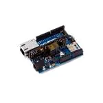
Ardu
uino Ettherne
et
Overview
w
The Ardu
uino Etherneet is a microcontroller bo
oard based o
on the ATmeega328 (dataasheet). It haas 14
digital in
nput/output pins, 6 analo
og inputs, a 16 MHz crysstal oscillato
or, a RJ45 co
onnection, a
power jacck, an ICSP header, and a reset button.
NB: Pinss 10, 11, 12 an
nd 13 are resserved for in
nterfacing w
with the Etheernet modulle and shoulld not
be used otherwise.
o
This
T
reduces the number of availablee pins to 9, w
with 4 availa
able as PWM
M
outputs.
An option
nal Power ov
ver Ethernett module can
n be added tto the board as well.
The Etheernet differs from other boards
b
in that it does no
ot have an on
nboard USB-to-serial drriver
chip, butt has a Wizneet Ethernet interface.
i
Th
his is the sam
me interface found on th
he Ethernet
shield.
An onboa
ard microSD
D card readerr, which can
n be used to sstore files fo
or serving ovver the netwo
ork,
is accessiible through
h the SD Librrary. Pin 10 is
i reserved ffor the Wizn et interface, SS for the S
SD
card is on
n Pin 4.
The 6-pin
n serial prog
gramming heeader is com
mpatible with
h the USB Seerial adapterr and also wiith
the FTDII USB cabless or with Spa
arkfun and Adafruit
A
FTD
DI-style basicc USB-to-serial breakou
ut
boards. It
I features su
upport for au
utomatic reset, allowing sketches to be uploaded
d without
pressing the reset bu
utton on the board.
b
When
n plugged in
nto a USB to Serial adaptter, the Ardu
uino
Ethernett is powered from the adapter.
Summarry
Microcon
ntroller
ATmega328
8
Operatin
ng Voltage
5V
Input Vo
oltage Plug (rrecommendeed)
7-12V
Input Vo
oltage Plug (llimits)
6-20V
Input Vo
oltage PoE (liimits)
36-57V
Digital I//O Pins
h 4 provide P
PWM outputt)
14 (of which
Arduino Pinss reserved:
10 to 13 used for S
SPI
4 used for SD carrd
2 W5100 interrup
pt (when bridged
d)
�nput Pins
Analog In
6
DC Curreent per I/O Pin
P
40 mA
DC Curreent for 3.3V Pin
50 mA
Flash Meemory
mega328) of which 0.5 K
KB used by
32 KB (ATm
bootloader
SRAM
2 KB (ATmeega328)
M
EEPROM
1 KB (ATmeega328)
Clock Speed
16 MHz
W5100 TCP/IP
T
Embedded Etherrnet
Controlleer
Power Ov
ver Ethernett ready Magn
netic Jack
Micro SD
D card, with active voltag
ge
translato
ors
Schemattic & Referen
nce Design
EAGLE files:
f
arduino
o-ethernet-rreference-dessign.zip
Schematiic: arduino-eethernet-sch
hematic.pdf
Power
The boarrd can also be
b powered via
v an extern
nal power sup
pply, an optiional Powerr over Ethern
net
(PoE) mo
odule, or by using a FTD
DI cable/USB
B Serial conn
nector.
External power can come
c
either from
f
an AC--to-DC adap
pter (wall-waart) or batterry. The adap
pter
can be co
onnected by plugging a 2.1mm
2
centeer-positive pllug into the board's pow
wer jack. Leaads
from a ba
attery can bee inserted in
n the Gnd and Vin pin heeaders of thee POWER co
onnector.
The boarrd can operate on an exteernal supplyy of 6 to 20 vvolts. If supp
plied with lesss than 7V,
however,, the 5V pin may supply less than fiv
ve volts and tthe board m
may be unstab
ble. If using
more tha
an 12V, the voltage
v
regullator may ov
verheat and d
damage the b
board. The rrecommendeed
range is 7 to 12 volts..
The poweer pins are as
a follows:
VIN.. The input voltage
v
to the Arduino board when itt's using an external pow
wer source (as
opposed to 5 voltts from the USB
U connecttion or otherr regulated p
power sourcee). You can
supplly voltage th
hrough this pin,
p or, if sup
pplying voltaage via the p
power jack, aaccess it thro
ough
this pin.
p
5V. This
T
pin outp
puts a regula
ated 5V from
m the regulattor on the bo
oard. The bo
oard can be
suppllied with pow
wer either frrom the DC power
p
jack ((7 - 12V), thee USB conneector (5V), orr the
�
VIN pin
p of the bo
oard (7-12V). Supplying voltage
v
via tthe 5V or 3.3
3V pins bypaasses the
regullator, and can damage yo
our board. We
W don't advvise it.
3V3.. A 3.3 volt supply generrated by the on-board
o
reggulator. Maxximum curreent draw is 5
50
mA.
GND
D. Ground piins.
The optio
onal PoE mo
odule is desig
gned to extract power frrom a conven
ntional twistted pair Cateegory
5 Ethernet cable:
IEEE
E802.3af com
mpliant
Low output
o
ripple and noise (100mVpp)
Inputt voltage ran
nge 36V to 57
7V
Overlload and sho
ort-circuit prrotection
9V Output
High efficiency DC/DC
D
conveerter: typ 75% @ 50% lo
oad
1500V
V isolation (input
(
to outtput)
NB: the Power
P
over Ethernet
E
mo
odule is prop
prietary harrdware not m
made by Arduino, it is a
third parrty accessorry. For moree information
n, see the da
atasheet
When using the poweer adapter, power
p
can co
ome either fr
from an AC-tto-DC adaptter (wall-warrt) or
battery. The
T adapter can be conn
nected by plu
ugging a 2.1m
mm center-p
positive plug
g into the board's
power jacck. Leads fro
om a batteryy can be inseerted in the G
Gnd and Vin
n pin headerss of the POW
WER
connecto
or.
The boarrd can operate on an exteernal supplyy of 6 to 20 vvolts. If supp
plied with lesss than 7V,
however,, the 5V pin may supply less than fiv
ve volts and tthe board m
may be unstab
ble. If using
more tha
an 12V, the voltage
v
regullator may ov
verheat and d
damage the b
board. The rrecommendeed
range is 7 to 12 volts..
Memory
The ATm
mega328 has 32 KB (with
h 0.5 KB useed for the boo
otloader). Itt also has 2 K
KB of SRAM
M and
1 KB of EEPROM
E
(wh
hich can be read and wrritten with th
he EEPROM
M library).
Input and Output
Each of the
t 14 digitall pins on thee Ethernet bo
oard can be used as an in
nput or outp
put, using
pinModee(), digitalWrrite(), and digitalRead()
d
) functions. T
They operatee at 5 volts. E
Each pin can
n
provide or
o receive a maximum
m
off 40 mA and
d has an inteernal pull-up
p resistor (disconnected b
by
default) of
o 20-50 kOh
hms. In add
dition, some pins
p
have sp
pecialized fu
unctions:
Seria
al: 0 (RX) and
a
1 (TX)). Used to recceive (RX) aand transmitt (TX) TTL sserial data.
Exte
ernal Interr
rupts: 2 an
nd 3. These pins
p
can be configured tto trigger an
n interrupt on
na
low value,
v
a rising or falling edge,
e
or a ch
hange in valu
ue. See the atttachInterru
upt() functio
on for
detaills.
PWM
M: 3, 5, 6, 9,
9 and 10. Provide
P
8-bitt PWM outp
put with the aanalogWritee() function.
SPI: 10 (SS), 111 (MOSI), 12
1 (MISO), 13 (SCK). These pins ssupport SPI communicaation
using
g the SPI librrary.
LED: 9. There iss a built-in LED
L
connectted to digitall pin 9. When
n the pin is H
HIGH valuee, the
LED is on, when the pin is LO
OW, it's off. On most oth
her arduino b
boards, this LED is foun
nd on
�pin 13
3. It is on pin
n 9 on the Ethernet
E
boarrd because p
pin 13 is used
d as part of tthe SPI
connection.
The Etheernet board has
h 6 analog
g inputs, labeeled A0 thro
ough A5, each
ch of which p
provide 10 biits of
resolutio
on (i.e. 1024 different vallues). By deffault they meeasure from ground to 5 volts, thoug
gh is
it possiblle to change the upper en
nd of their range using tthe AREF pi n and the an
nalogReferen
nce()
function.. Additionallly, some pinss have specialized functiionality:
TWII: A4 (SDA)) and A5 (S
SCL). Suppo
ort TWI com
mmunication
n using the W
Wire library.
There aree a couple off other pins on
o the board
d:
ARE
EF. Referencce voltage forr the analog inputs. Used
d with analo
ogReference(().
Rese
et. Bring thiss line LOW to
t reset the microcontro
m
oller. Typicallly used to ad
dd a reset bu
utton
to shiields which block
b
the on
ne on the boa
ard.
See also the
t mapping
g between Arrduino pins and ATmegaa328 ports.
Commun
nication
The Ardu
uino Etherneet has a num
mber of facilities for com municating with a comp
puter, another
Arduino,, or other miicrocontrolleers.
A Softwa
areSerial librrary allows fo
or serial com
mmunication
n on any of th
he Uno's dig
gital pins.
The ATm
mega328 also
o supports TWI
T
and SPI communicaation. The Arrduino softw
ware includess a
Wire librrary to simpllify use of th
he TWI bus; see
s the docu
umentation ffor details. F
For SPI
commun
nication, use the SPI libra
ary.
The boarrd also can co
onnect to a wired
w
netwo
ork via ethern
net. When cconnecting to
o a network, you
will need
d to provide an
a IP addresss and a MAC
C address. T
The Ethernett Library is ffully supportted.
The onbo
oard microSD card readeer is accessib
ble through the SD Libraary. When w
working with
h this
library, SS
S is on Pin 4.
4
Program
mming
It is posssible to progrram the Arduino Ethern
net board in ttwo ways: th
hrough the 6 pin serial
programming headerr, or with an
n external ISP
P programm
mer.
The 6-pin
n serial prog
gramming heeader is com
mpatible with
h FTDI USB cables and tthe Sparkfun
n and
Adafruit FTDI-style basic
b
USB-to
o-serial brea
akout boardss including tthe Arduino USB-Serial
connecto
or. It features support for automatic reset, allowiing sketchess to be uploaaded withoutt
pressing the reset bu
utton on the board.
b
When
n plugged in
nto a FTDI-sstyle USB adapter, the
Arduino Ethernet is powered
p
offf the adapterr.
You can also
a program
m the Ethern
net board with an extern
nal programm
mer like an A
AVRISP mkIII or
USBTiny
yISP. To set up
u your enviironment forr burning a ssketch with a programm
mer, follow th
hese
instructio
ons. This willl delete the serial bootlo
oader, howevver.
All the Etthernet exam
mple sketchees work as th
hey do with tthe Ethernett shield. Mak
ke sure to
change th
he network settings
s
for your
y
network
k.
�Physical Characterisstics
The maxiimum length
h and width of the Etherrnet PCB aree 2.7 and 2.1 inches respectively, witth the
RJ45 con
nnector and power jack extending
e
beeyond the fo
ormer dimen
nsion. Four sscrew holes aallow
the board
d to be attach
hed to a surfface or case.. Note that th
he distance b
between dig
gital pins 7 an
nd 8
is 160 miil (0.16"), no
ot an even multiple
m
of thee 100 mil sp
pacing of thee other pins.
Setup
If you wa
ant to use a FTDI
F
cable to
t download your sketch
hes on the Arrduino Etherrnet, please refer
to this gu
uide: Upgrad
de the Arduino Ethernett bootloader to the latestt version
�


 工商网监
湘ICP备2023018690号
工商网监
湘ICP备2023018690号
