Adafruit MPR121 12-Key Capacitive Touch
Sensor Breakout Tutorial
Created by lady ada
https://learn.adafruit.com/adafruit-mpr121-12-key-capacitive-touch-sensor-breakout-tutorial
Last updated on 2022-07-18 03:41:17 PM EDT
©Adafruit Industries
Page 1 of 30
�Table of Contents
Overview
3
Pinouts
5
•
•
•
•
Power Pins
I2C Pins
IRQ and ADDR Pins
Assembly
7
• Prepare the header strip:
• Add the breakout board:
• And Solder!
Arduino
•
•
•
•
•
Download Adafruit_MPR121
Load Demo
Library Reference
Touch detection
Raw Data
Python & CircuitPython
•
•
•
•
•
•
9
16
CircuitPython Microcontroller Wiring
Python Computer Wiring
CircuitPython Installation of MPR121 Library
Python Installation of MPR121 Library
CircuitPython & Python Usage
Full Example Code
Python Docs
23
Raspberry Pi Virtual Keyboard
23
•
•
•
•
•
•
Wiring
Dependencies
Configuration
Usage
Launch In Background
Stop Background Process
Electrodes
27
Downloads
28
• Datasheets & Files
• STEMMA QT Revision Schematic and Fab Print
• Original Breakout Board Schematic and Fab Print
©Adafruit Industries
Page 2 of 30
�Overview
Add lots of touch sensors to your next microcontroller project with this easy-to-use 12channel capacitive touch sensor breakout board, starring the MPR121. This chip can
handle up to 12 individual touch pads.
The MPR121 has support for only I2C, which can be implemented with nearly any
microcontroller. You can select one of 4 addresses with the ADDR pin, for a total of 48
capacitive touch pads on one I2C 2-wire bus. Using this chip is a lot easier than doing
the capacitive sensing with analog inputs: it handles all the filtering for you and can
be configured for more/less sensitivity.
©Adafruit Industries
Page 3 of 30
�This sensor comes as a tiny hard-to-solder chip so we put it onto a breakout board for
you. Since it's a 3V-only chip, we added a 3V regulator and I2C level shifting so its
safe to use with any 3V or 5V microcontroller/processor like Arduino. We even added
an LED onto the IRQ line so it will blink when touches are detected, making
debugging by sight a bit easier on you. Comes with a fully assembled board, and a
stick of 0.1" header so you can plug it into a breadboard. For contacts, we suggest
using copper foil or pyralux, then solder a wire that connects from the foil pad to the
breakout.
As if that weren't enough, we've now also added SparkFun qwiic (https://adafru.it/
Fpw) compatible STEMMA QT (https://adafru.it/Ft4) connectors for the I2C bus so you
©Adafruit Industries
Page 4 of 30
�don't even need to solder the I2C and power lines. Just wire up to your favorite micro
using a STEMMA QT adapter cable. (https://adafru.it/JnB) The Stemma QT connectors
also mean the MPR121 can be used with our various associated accessories. (https://
adafru.it/Ft6) QT Cable is not included, but we have a variety in the shop (https://
adafru.it/JnB).
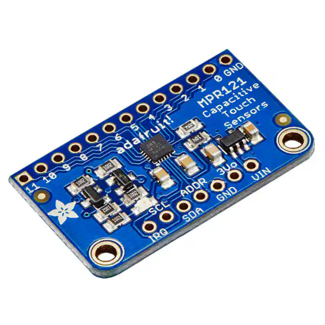
There are two versions of this board - the STEMMA QT version shown above, and
the original header-only version shown below. Code works the same on both!
Pinouts
©Adafruit Industries
Page 5 of 30
�The pins are in a slightly different order on the original board from the STEMMA
QT version. They function the same!
The little chip in the middle of the PCB is the actual MPR121 sensor that does all the
capacitive sensing and filtering. We add all the extra components you need to get
started, and 'break out' all the other pins you may want to connect to onto the PCB.
For more details you can check out the schematics in the Downloads page.
Power Pins
The sensor on the breakout requires 3V power. Since many customers have 5V
microcontrollers like Arduino, we tossed a 3.3V regulator on the board. Its ultra-low
dropout so you can power it from 3.3V-5V just fine.
• Vin - this is the power pin. Since the chip uses 3 VDC, we have included a
voltage regulator on board that will take 3-5VDC and safely convert it down. To
power the board, give it the same power as the logic level of your
microcontroller - e.g. for a 5V micro like Arduino, use 5V
• 3Vo - this is the 3.3V output from the voltage regulator, you can grab up to
100mA from this if you like
• GND - common ground for power and logic
©Adafruit Industries
Page 6 of 30
�I2C Pins
• SCL - I2C clock pin, connect to your microcontroller's I2C clock line.
• SDA - I2C data pin, connect to your microcontroller's I2C data line.
IRQ and ADDR Pins
• ADDR is the I2C address select pin. By default this is pulled down to ground
with a 100K resistor, for an I2C address of 0x5A. You can also connect it to the
3Vo pin for an address of 0x5B, the SDA pin for 0x5C or SCL for address 0x5D
• INT (IRQ on original version) is the Interrupt Request signal pin. It is pulled up to
3.3V on the breakout and when the sensor chip detects a change in the touch
sense switches, the pin goes to 0V until the data is read over i2c
Assembly
©Adafruit Industries
Page 7 of 30
�Prepare the header strip:
Cut the strip to length if necessary. It will
be easier to solder if you insert it into a
breadboard - long pins down
Add the breakout board:
Place the breakout board over the pins so
that the short pins poke through the
breakout pads
©Adafruit Industries
Page 8 of 30
�And Solder!
Be sure to solder all pins for reliable
electrical contact.
(For tips on soldering, be sure to check out
our Guide to Excellent Soldering (https://
adafru.it/aTk)).
You're done! Check your solder joints visually and continue onto the next steps
Arduino
You can easily wire this breakout to any microcontroller, we'll be using an Arduino. For
another kind of microcontroller, just make sure it has I2C, then port the code - its
pretty simple stuff!
©Adafruit Industries
Page 9 of 30
�Connect Vin to the power supply, 3-5V is
fine. Use the same voltage that the
microcontroller logic is based off of. For
most Arduinos, that is 5V
Connect GND to common power/data
ground
Connect the SCL pin to the I2C clock SCL
pin on your Arduino. On an UNO & '328
based Arduino, this is also known as A5,
on a Mega it is also known as digital 21
and on a Leonardo/Micro, digital 3
Connect the SDA pin to the I2C data SDA
pin on your Arduino. On an UNO & '328
based Arduino, this is also known as A4,
on a Mega it is also known as digital 20
and on a Leonardo/Micro, digital 2
The MPR121 ADDR pin is pulled to ground and has a default I2C address of 0x5A
You can adjust the I2C address by connecting ADDR to other pins:
• ADDR not connected: 0x5A
• ADDR tied to 3V: 0x5B
• ADDR tied to SDA: 0x5C
• ADDR tied to SCL: 0x5D
We suggest sticking with the default for the test demo, you can always change it later.
©Adafruit Industries
Page 10 of 30
�Download Adafruit_MPR121
To begin reading sensor data, you will need to download the Adafruit_MPR121 library
from the Arduino library manager.
Open up the Arduino library manager:
Seach for the Adafruit MPR121 library and install it
We also have a great tutorial on Arduino library installation at:
http://learn.adafruit.com/adafruit-all-about-arduino-libraries-install-use (https://
adafru.it/aYM)
Load Demo
Open up File->Examples->Adafruit_MPR121->MPR121test and upload to your Arduino
wired up to the sensor
©Adafruit Industries
Page 11 of 30
�Thats it! Now open up the serial terminal window at 9600 speed to begin the test.
Make sure you see the "MPR121 found!" text which lets you know that the sensor is
wired correctly.
Now touch the 12 pads with your fingertip to activate the touch-detection
©Adafruit Industries
Page 12 of 30
�©Adafruit Industries
Page 13 of 30
�For most people, that's all you'll need! Our code keeps track of the 12 'bits' for each
touch and has logic to let you know when a contect is touched or released.
If you're feeling more advanced, you can see the 'raw' data from the chip. Basically,
what it does it keep track of the capacitance it sees with "counts". There's some
baseline count number that depends on the temperature, humidity, PCB, wire length
etc. Where's a dramatic change in number, its considered that a person touched or
released the wire.
Comment this "return" line to activate that mode:
©Adafruit Industries
Page 14 of 30
�// comment out this line for detailed data from the sensor!
return;
Then reupload. Open up the serial console again - you'll see way more text
Each reading has 12 columns. One for each sensor, #0 to #11. There's two rows, one
for the 'baseline' and one for the current filtered data reading. When the current
reading is within about 12 counts of the baseline, that's considered untouched. When
the reading is more than 12 counts smaller than the baseline, the chip reports a touch.
Most people don't need raw data too much, but it can be handy if doing intense
debugging. It can be helpful if you are tweaking your sensors to get good
responsivity.
Library Reference
Since the sensors use I2C, there's no pins to be defined during instantiation. You can
just use:
Adafruit_MPR121 cap = Adafruit_MPR121();
When you initialize the sensor, pass in the I2C address. It can range from 0x5A
(default) to 0x5D
cap.begin(0x5A)
begin() returns true if the sensor was found on the I2C bus, and false if not.
©Adafruit Industries
Page 15 of 30
�Touch detection
99% of users will be perfectly happy just querying what sensors are currentlt touched.
You can read all at once with
cap.touched()
Which returns a 16 bit value. Each of the bottom 12 bits refers to one sensor. So if you
want to test if the #4 is touched, you can use
if (cap.touched() & (1 > prompt.
Python Installation of MPR121 Library
You'll need to install the Adafruit_Blinka library that provides the CircuitPython
support in Python. This may also require enabling I2C on your platform and verifying
you are running Python 3. Since each platform is a little different, and Linux changes
often, please visit the CircuitPython on Linux guide to get your computer ready (https:
//adafru.it/BSN)!
Once that's done, from your command line run the following command:
• sudo pip3 install adafruit-circuitpython-mpr121
If your default Python is version 3 you may need to run 'pip' instead. Just make sure
you aren't trying to use CircuitPython on Python 2.x, it isn't supported!
CircuitPython & Python Usage
To demonstrate the usage of the sensor, we'll initialize it and read capacitive touch
from the board's Python REPL.
If you're using an I2C connection, run the following code to import the necessary
modules and initialize the I2C connection with the sensor:
import time
import board
import busio
import adafruit_mpr121
i2c = busio.I2C(board.SCL, board.SDA)
mpr121 = adafruit_mpr121.MPR121(i2c)
Now you're ready to read capacitive touch from the sensor. Use the following syntax
to check a specific pin.
• mpr121[i].value - Return True if the specified pin is being touched, otherwise
returns False .
©Adafruit Industries
Page 21 of 30
�Use a value 0 to 11 for [i] and it will return a boolean True or False value depending
on if the input is currently being touched or not.
For example, to print when pin 0 is touched, run the following code, and then touch
pin 0:
while True:
if mpr121[0].value:
print("Pin 0 touched!")
If you don't see any messages when you touch the inputs, you might need to ground
yourself to the board by touching the GND pin on the board with one finger and then
touching the input pads with another finger.
Also make sure nothing is touching the pins when you first run the code, or else it
might confuse the MPR121's touch detection (unmount the board's file system from
your operating system, then press the board's reset button to reset the script and run
it again with nothing touching the pins). The pins are calibrated on start-up, and will
not react properly if you're touching the pins when the board starts up.
To print when any pin is touched, run the following code and then touch any
capacitive touch pin:
while True:
for i in range(12):
if mpr121[i].value:
print('Input {} touched!'.format(i))
The example doesn't show its usage, but if you want to check all of the inputs at once
you can use touched_pins . This function returns a 12 member tuple of the current
state for each of the 12 pins. True is touched and False is not touched. For
example, to test if pin 0 and 11 are being touched with one call you could run code
like:
©Adafruit Industries
Page 22 of 30
�# Use touched_pins to get current state of all pins.
touched = mpr121.touched_pins
# Test if 0 and 11 are touched.
if touched[0] and touched[11]:
print('Input 0 and 11 touched!')
That's all there is to using the MPR121 module with CircuitPython!
Full Example Code
# SPDX-FileCopyrightText: 2017 Tony DiCola for Adafruit Industries
# SPDX-License-Identifier: MIT
# Simple test of the MPR121 capacitive touch sensor library.
# Will print out a message when any of the 12 capacitive touch inputs of the
# board are touched. Open the serial REPL after running to see the output.
# Author: Tony DiCola
import time
import board
import busio
# Import MPR121 module.
import adafruit_mpr121
# Create I2C bus.
i2c = busio.I2C(board.SCL, board.SDA)
# Create MPR121 object.
mpr121 = adafruit_mpr121.MPR121(i2c)
# Note you can optionally change the address of the device:
# mpr121 = adafruit_mpr121.MPR121(i2c, address=0x91)
# Loop forever testing each input and printing when they're touched.
while True:
# Loop through all 12 inputs (0-11).
for i in range(12):
# Call is_touched and pass it then number of the input. If it's touched
# it will return True, otherwise it will return False.
if mpr121[i].value:
print("Input {} touched!".format(i))
time.sleep(0.25) # Small delay to keep from spamming output messages.
Python Docs
Python Docs (https://adafru.it/Cbi)
Raspberry Pi Virtual Keyboard
One great use for the MPR121 is as a capacitive touch keyboard, where pressing a
touch input causes a key to be pressed on a Raspberry Pi. This is kind of like a MaKey
MaKey (http://adafru.it/1068), but built right into the Pi using just the MPR121 and some
©Adafruit Industries
Page 23 of 30
�special software. You could for example configure the MPR121 to act as a giant
gamepad that controls games on the Raspberry Pi!
Wiring
To use the MPR121 as a virtual keyboard you'll first want to make sure you've followed
the earlier pages in this guide to connect the MPR121 to the Raspberry Pi and install
the software.
Dependencies
Now open a terminal on the Raspberry Pi using SSH and execute the following
commands to install a few dependencies required by the virtual keyboard script:
sudo
sudo
sudo
sudo
apt-get update
apt-get install libudev-dev
pip3 install python-uinput
pip3 install adafruit-circuitpython-mpr121
Configuration
After the dependencies are installed navigate to the MPR121 library examples folder
again. Open the pi_keyboard.py script in a text editor such as nano by executing:
nano pi_keyboard.py
Now scroll down to the key configuration near the top of the file:
KEY_MAPPING =
{
0:
uinput.KEY_UP,
1:
uinput.KEY_DOWN,
2:
uinput.KEY_LEFT,
3:
uinput.KEY_RIGHT,
4:
uinput.KEY_B,
5:
uinput.KEY_A,
6:
uinput.KEY_ENTER,
7:
©Adafruit Industries
Page 24 of 30
�uinput.KEY_SPACE,
}
The KEY_MAPPING variable is a dictionary that maps an input number on the MPR121
to a keyboard button that will be sent when the input is pressed.
For example the code above configures input 0 to the UP key, input 1 to the DOWN
key, input 2 to the LEFT key, etc.
Adjust the inputs and key codes depending on your needs. Most of the key codes
are self explanatory (i.e. the key code for the letter Q is uinput.KEY_Q ), but if you
are unsure of an input you can find the name of a keycode in the Linux input header
here (https://adafru.it/eik). Take the key name and add uinput. to the front of it to
get the key code that should be in the configuration above.
If you need to add more inputs you can add them as new lines after input 7 above. B
e careful to make sure each new line ends in a comma so the python dictionary is
defined correctly.
After you've configured your key mapping save the file by pressing Ctrl-O and Enter,
then quit by pressing Ctrl-X.
Usage
Now run the program by executing:
sudo python3 pi_keyboard.py
After a moment you should see a message displayed that tells you to press Ctrl-C to
quit the program. If you press inputs to the MPR121 they should send the keys you've
configured to the Raspberry Pi!
Note that you won't see any output from the program when keys are pressed, unless
you first enable logging by un-commenting the following line:
# Uncomment to enable debug message logging (might slow down key
detection).
logging.basicConfig(level=logging.DEBUG)
Quit the program by pressing Ctrl-C.
©Adafruit Industries
Page 25 of 30
�Launch In Background
Running the program by itself is great, but you probably want to run the program in
the background while a game or other application runs and takes input from the
MPR121 key presses. To do this you can launch the program into the background by
executing at the terminal:
sudo python keyboard.py &
You should see a response such as:
[1] 2251
This tells you the program is launched in the background and is currently running
under the process ID 2251. Try to remember the process ID as it will help you shut
down the program later (but don't worry, I'll show you how to shut down the program
even if you forget the ID).
Now run a game or other program that relies on keyboard input. Try pressing inputs
on the MPR121 and you should see them register as keyboard presses!
Stop Background Process
To stop the background process you'll need to tell Linux to kill the python keyboard.p
y process that was launched in the background earlier. If you remember the process
ID number you can skip below to the kill command. However if you forgot the
process ID number you can find it by executing a command like this to search all
running processes for the keyboard.py script:
ps aux | grep keyboard.py
You should see a list of processes such as:
root
2251 0.5
keyboard.py
root
2252 13.2
pi
2294 0.0
keyboard.py
0.3
5136
1488 pts/0
S
09:13
0:00 sudo python
1.4
0.2
18700
4096
5524 pts/0
804 pts/0
Sl
S+
09:13
09:13
0:00 python keyboard.py
0:00 grep --color=auto
The first line with sudo python keyboard.py is the background process that was
launched earlier. You can kill this process by running:
©Adafruit Industries
Page 26 of 30
�sudo kill 2251
If you run the ps command above again you should now see the Python keyboard.py
processes have terminated.
That's all there is to using the MPR121 virtual keyboard on a Raspberry Pi. Have fun
using the capacitive touch buttons to control your own games and programs!
Electrodes
Once you have the MPR121 breakout working you'll want to construct electrodes.
These are large conductive piece of copper, foil, paint, etc that will act as the "thing
you touch"
Remember that electrodes must be electrically conductive! We suggest copper foil
tape, conductive fabrics, ITO, pyralux flex PCB, etc. We have tons of great conductive
materials in our Materials category. Some can be soldered to, others can be clipped
to with alligator chips. (https://adafru.it/dKI)
Remember, it doesn't have to be metal to be electrically conductive. Other things that
work are tap or salt water, many kinda of food, even fruit!
We suggest soldering a wire to the electrode pad on the breakout and then soldering
or clipping it to whatever you want your electrode to be.
©Adafruit Industries
Page 27 of 30
�The wires and electrodes themselves have a certain amount of 'inherent
capacitcance'!
This means that whenever you attach an alligator clip, or a large piece of copper, or
whatever your electrode is, the capacitive sense chip will detect it and may think
you're touching it. What you have to do is recalibrate the sensor. The easiest way to
do that is to restart the python sketch since calibration is done when the chip is
initialized. So, basically...
connect all your wires, electrodes, fruit, etc...then start up the capacitive touch
program!
Downloads
Datasheets & Files
• MPR121 Datasheet (https://adafru.it/dKG)
• EagleCAD PCB files on GitHub (https://adafru.it/pJa)
• Fritzing object in Adafruit Fritzing library (https://adafru.it/c7M)
STEMMA QT Revision Schematic and Fab
Print
©Adafruit Industries
Page 28 of 30
�Original Breakout Board Schematic and Fab Print
©Adafruit Industries
Page 29 of 30
�©Adafruit Industries
Page 30 of 30
�


 工商网监
湘ICP备2023018690号
工商网监
湘ICP备2023018690号
