Adafruit VEML6070 UV Sensor Breakout
Created by lady ada
https://learn.adafruit.com/adafruit-veml6070-uv-light-sensor-breakout
Last updated on 2021-11-15 06:42:04 PM EST
©Adafruit Industries
Page 1 of 15
�Table of Contents
Overview
3
Pinouts
4
• Power Pins:
• I2C Pins
• Other
5
5
5
Assembly
5
• Prepare the header strip:
• Add the breakout board:
• And Solder!
6
6
7
Arduino
7
• Wiring for Arduino
• Install Library
• Load Demo
7
8
9
Python & CircuitPython
11
•
•
•
•
•
•
11
11
12
13
13
14
CircuitPython Microcontroller Wiring
Python Computer Wiring
CircuitPython Installation of VEML6070 Library
Python Installation of VEML6070 Library
CircuitPython & Python Usage
Full Example Code
Downloads
14
• Schematic
• Fabrication Print
14
15
©Adafruit Industries
Page 2 of 15
�Overview
This little sensor is a great way to add UV light sensing to any microcontroller project.
The VEML6070 from Vishay has a true UV A light sensor and an I2C-controlled ADC
that will take readings and integrate them for you over ~60ms to 500ms.
Unlike the Si1145 (http://adafru.it/1777), this sensor will not give you UV Index
readings. However, the Si1145 does UV Index approximations based on light level not
true UV sensing. The VEML6070 in contrast does have a real light sensor in the UV
spectrum. It's also got a much much simpler I2C interface so you can run it on the
smallest microcontrollers with ease.
Unlike the GUVA analog sensor (http://adafru.it/1918), the biasing and ADC is all
internal so you don't need an ADC.
©Adafruit Industries
Page 3 of 15
�This UV sensor works great with 3 or 5V power or logic, its nice and compact, and its
easy to use with any I2C-capable microcontroller.
Each order comes with one assembled PCB with a sensor, some handy pullup
resistors, a 270K rset resistor and a small piece of header. Some light soldering is
required to attach the header but its a fast task!
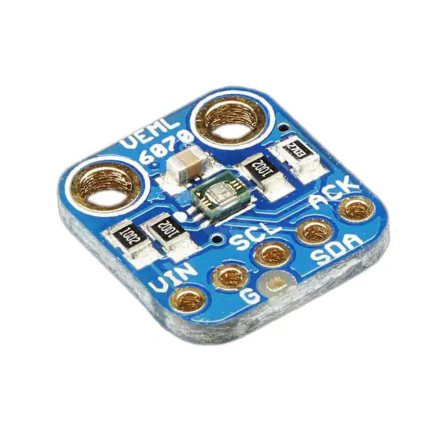
Pinouts
©Adafruit Industries
Page 4 of 15
�Power Pins:
• Vin - this is the power pin. The sensor chip uses 3 to 5 VDC, so you can use it
with just about any microcontroller. To power the board, give it the same power
as the logic level of your microcontroller - e.g. for a 5V micro like Arduino, use
5V
• GND - common ground for power and logic
I2C Pins
• SCL - I2C clock pin, connect to your microcontrollers I2C clock line. This pin can
be used with 3V or 5V logic, and there's a 10K pullup on this pin.
• SDA - I2C data pin, connect to your microcontrollers I2C data line. This pin can
be used with 3V or 5V logic, and there's a 10K pullup on this pin.
Other
• ACK Pin - This is the interrupt/alert output. You can set up the sensor to warn
you on overly high or low UV signal. Logic level is the same as whatever you set
Vin
Assembly
©Adafruit Industries
Page 5 of 15
�Prepare the header strip:
Cut the strip to length if necessary. It will
be easier to solder if you insert it into a
breadboard - long pins down
Add the breakout board:
Place the breakout board over the pins
so that the short pins poke through the
breakout pads
©Adafruit Industries
Page 6 of 15
�And Solder!
Be sure to solder all pins for reliable
electrical contact.
Solder the longer power/data strip first
(For tips on soldering, be sure to check
out our Guide to Excellent
Soldering (https://adafru.it/aTk)).
You're done! Check your solder joints
visually and continue onto the next steps
Arduino
Wiring for Arduino
You can easily wire this breakout to any microcontroller, we'll be using an Arduino. For
another kind of microcontroller, just make sure it has I2C capability, then port the
code - its pretty simple stuff!
©Adafruit Industries
Page 7 of 15
�• Connect Vin to the power supply, 3-5V is fine. Use the same voltage that the
microcontroller logic is based off of. For most Arduinos, that is 5V
• Connect GND to common power/data ground
• Connect the SCL pin to the I2C clock SCL pin on your Arduino. On an UNO &
'328 based Arduino, this is also known as A5, on a Mega it is also known as digi
tal 21 and on a Leonardo/Micro, digital 3
• Connect the SDA pin to the I2C data SDA pin on your Arduino. On an UNO &
'328 based Arduino, this is also known as A4, on a Mega it is also known as digi
tal 20 and on a Leonardo/Micro, digital 2
Install Library
To begin reading sensor data, you will need to download the Adafruit VEML6070 libr
ary from the Arduino library manager.
Open up the Arduino library manager:
©Adafruit Industries
Page 8 of 15
�Search for the Adafruit VEML6070 library and install it
We also have a great tutorial on Arduino library installation at:
http://learn.adafruit.com/adafruit-all-about-arduino-libraries-install-use (https://
adafru.it/aYM)
Load Demo
Open up File->Examples->Adafruit_VEML6070->vemltest and upload to your Arduino
wired up to the sensor
Upload to the Arduino and open up the serial console at 9600 baud to see the UV
data output. Note that this is not UV index, its just UV light intensity!
©Adafruit Industries
Page 9 of 15
�If you're integrating this sensor into your project, its fairly easy to do.
Start by instantiating the sensor with:
Adafruit_VEML6070 uv = Adafruit_VEML6070();
Note that since this a pure I2C sensor, there's not pin configuration for instantiation
Next, you will call begin() in your setup procedure. There are 4 different 'integration'
times used to calculate the intensity. The longer the integration time, the more light is
collected. Use shorter integration times if you want to get measurements quickly with
less precision. Longer times will give you more precision but of course, take longer!
• VEML6070_HALF_T ~62.5ms
• VEML6070_1_T ~125ms
• VEML6070_2_T ~250ms
• VEML6070_4_T ~500ms
Pass the integration time constant into begin like:
uv.begin(VEML6070_1_T)
©Adafruit Industries
Page 10 of 15
�Then you can call readUV which will give you a 16-bit value relating to how much UV
was detected. Again, this is not an UV index value, its unitless. You may need to
calibrate the value against a known value depending on your usage!
Python & CircuitPython
It's easy to use the VEML6070 sensor with Python or CircuitPython and the Adafruit
CircuitPython VEML6070 (https://adafru.it/C6-) module. This module allows you to
easily write Python code that reads the UV index from the sensor.
You can use this sensor with any CircuitPython microcontroller board or with a
computer that has GPIO and Python thanks to Adafruit_Blinka, our CircuitPython-forPython compatibility library (https://adafru.it/BSN).
CircuitPython Microcontroller Wiring
First wire up a VEML6070 to your board exactly as shown in the previous pages for
Arduino. Here's an example of wiring a Feather M0 to the sensor with I2C:
• Board 3V to sensor VIN
• Board GND to sensor G
• Board SCL to sensor SCL
• Board SDA to sensor SDA
Python Computer Wiring
Since there's dozens of Linux computers/boards you can use we will show wiring for
Raspberry Pi. For other platforms, please visit the guide for CircuitPython on Linux to
see whether your platform is supported (https://adafru.it/BSN).
Here's the Raspberry Pi wired with I2C:
©Adafruit Industries
Page 11 of 15
�• Pi 3V3 to sensor VIN
• Pi GND to sensor GND
• Pi SCL to sensor SCK
• Pi SDA to sensor SDA
CircuitPython Installation of VEML6070
Library
You'll need to install the Adafruit CircuitPython VEML6070 (https://adafru.it/C6-) library
on your CircuitPython board.
First make sure you are running the latest version of Adafruit CircuitPython (https://
adafru.it/Amd) for your board.
Next you'll need to install the necessary libraries to use the hardware--carefully follow
the steps to find and install these libraries from Adafruit's CircuitPython library bundle
(https://adafru.it/uap). Our Welcome to CircuitPython guide has a great page on how
to install the library bundle (https://adafru.it/ABU).
For non-express boards like the Trinket M0 or Gemma M0, you'll need to manually
install the necessary libraries from the bundle:
• adafruit_veml6070.mpy
• adafruit_bus_device
Before continuing make sure your board's lib folder or root filesystem has the adafrui
t_veml6070.mpy, and adafruit_bus_device files and folders copied over.
Next connect to the board's serial REPL (https://adafru.it/Awz) so you are at the
CircuitPython >>> prompt.
©Adafruit Industries
Page 12 of 15
�Python Installation of VEML6070 Library
You'll need to install the Adafruit_Blinka library that provides the CircuitPython
support in Python. This may also require enabling I2C on your platform and verifying
you are running Python 3. Since each platform is a little different, and Linux changes
often, please visit the CircuitPython on Linux guide to get your computer ready (https
://adafru.it/BSN)!
Once that's done, from your command line run the following command:
• sudo pip3 install adafruit-circuitpython-veml6070
If your default Python is version 3 you may need to run 'pip' instead. Just make sure
you aren't trying to use CircuitPython on Python 2.x, it isn't supported!
CircuitPython & Python Usage
To demonstrate the usage of the sensor we'll initialize it and read the UV index from
the board's Python REPL.
First, run the following code to import the necessary modules:
import time
import board
import adafruit_veml6070
Now you're ready to setup the sensor and read the values using these properties:
• read - reads and returns the value of the UV intensity
• get_index - the UV Risk Level based on the captured UV reading
For example, run the following to setup the I2C object, get the raw UV reading, use
that reading to determine the risk level:
with board.I2C() as i2c:
uv = adafruit_veml6070.VEML6070(i2c)
uv_raw = uv.read
risk_level = uv.get_index(uv_raw)
Then you can print the results:
©Adafruit Industries
Page 13 of 15
�print('Reading: {0} | Risk Level: {1}'.format(uv_raw, risk_level))
That's all there is to using VEML6070 with Python and CircuitPython!
Full Example Code
# SPDX-FileCopyrightText: 2021 ladyada for Adafruit Industries
# SPDX-License-Identifier: MIT
# VEML6070 Driver Example Code
import time
import board
import adafruit_veml6070
with board.I2C() as i2c:
uv = adafruit_veml6070.VEML6070(i2c)
# Alternative constructors with parameters
# uv = adafruit_veml6070.VEML6070(i2c, 'VEML6070_1_T')
# uv = adafruit_veml6070.VEML6070(i2c, 'VEML6070_HALF_T', True)
# take 10 readings
for j in range(10):
uv_raw = uv.uv_raw
risk_level = uv.get_index(uv_raw)
print("Reading: {0} | Risk Level: {1}".format(uv_raw, risk_level))
time.sleep(1)
Downloads
• PCB files at https://github.com/adafruit/Adafruit-VEML6070-PCB (https://
adafru.it/nCi)
• Library files at https://github.com/adafruit/Adafruit_VEML6070 (https://adafru.it/
nCd)
• Fritzing object available in the Adafruit Fritzing Library (https://adafru.it/aP3)
• VEML6070 Datasheet (https://adafru.it/rsE)
Schematic
Click to embiggen
©Adafruit Industries
Page 14 of 15
�Fabrication Print
Dimensions in inches
©Adafruit Industries
Page 15 of 15
�


 工商网监
湘ICP备2023018690号
工商网监
湘ICP备2023018690号
