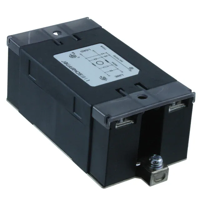
1-phase filters
FN 2450
Safe and ergonomic EMC/EMI filter with
very low leakage current
n
n
n
n
n
n
Light weight plastic enclosure design
Very low filter leakage current
Hinged safety covers
Embedded filter terminals
Different performance levels
Environmental friendly design without
potting compound
Technical specifications
Maximum continuous operating voltage:
Operating frequency:
Rated currents:
High potential test voltage:
Temperature range (operation and storage):
Flammability corresponding to:
Design corresponding to:
MTBF @ 40°C/230V (Mil-HB-217F):
Approvals
UL: pending
Typical electrical schematic
250VAC, 50/60Hz
dc to 400Hz
6 to 20A @ 55°C
P/N –> E 2500VAC for 60 sec*
P –> N 1100VDC for 2 sec
-25°C to +100°C (25/100/21)
UL 94V-0 (safety covers UL 94V-1)
UL 1283, CSA 22.2 No. 8 1986,
IEC/EN 60939, EN 60601-1
>180,000 hours
Cx-1
R
L
Cx-2
Cy
P
P‘
N
N‘
PE
Cy
Line
* Type testing only
Features and benefits
n
n
A plastic housing and a metal ground plate
Very low leakage current values make
n
Electrical and electronic equipment
are cleverly combined to get the lowest
the filters suitable for grids with very
n
Test and measurement devices
possible product weight without compro-
tough requirements or sensitive GFCIs,
n
Medical devices
mising EMC behavior.
and for applications which set value on
n
Industrial automation
safety and reliability.
n
Small machines
FN 2450 feature an ecologically conscious
n
Office automation equipment
n
The embedded terminals from Schaffner
guarantee user-friendly handling and reli-
n
Typical applications
n
able, long-lasting electrical connection.
construction without the use of potting
Captive hinged protective covers contri-
compound or banned substances (RoHS).
bute to overall safety by offering protection
Used raw materials can be easily separated
against unintended contact with life con-
at the end of the product life time for pro-
ductors. They are included in the standard
per and environmentally safe disposal.
scope of delivery without any extra cost.
Load
�> Components > FN 2450
Filter selection table
Filter*
Rated current
Leakage
Inductance
Capacitance
Resistance
Input/Output
@ 55°C (40°C)
current**
L
Cx
Cy
R
connections
@ 230VAC/50Hz
[A]
[mA]
[mH]
[μF] [nF]
[MΩ]
FN 2450G-6-61
6
(6.8)
0.73
10.5
0.47
4.7
1
-61
FN 2450G-10-61
10 (11.4)
0.73
4.9
0.47
4.7
1
-61
FN 2450G-16-61
16 (18.2)
0.73
1.84
0.47
4.7
1
-61
FN 2450G-20-61
20 (22.8)
0.73
0.94
0.47
4.7
1
-61
FN 2450F-6-61
6
(6.8)
0.52
10.5
0.47
3.3
1
-61
FN 2450F-10-61
10 (11.4)
0.52
4.9
0.47
3.3
1
-61
FN 2450F-16-61
16 (18.2)
0.52
1.84
0.47
3.3
1
-61
FN 2450F-20-61
20 (22.8)
0.52
0.94
0.47
3.3
1
-61
FN 2450B-6-61
6
(6.8)
0.002
10.5
0.47
1
-61
FN 2450B-10-61
10 (11.4)
0.002
4.9
0.47
1
-61
FN 2450B-16-61
16 (18.2)
0.002
1.84
0.47
1
-61
FN 2450B-20-61
20 (22.8)
0.002
0.94
0.47
1
-61
Weight
[g]
210
210
210
210
210
210
210
210
210
210
210
210
*
The letter following FN 2450_ represents the value of the Y-capacitor and is directly related to the performance and leakage current of the filter. Other Y-capacitor values are available upon request.
**
Maximum leakage current under normal operating conditions. Note: if the neutral line is interrupted, worst case leakage could reach twice this level.
Typical filter attenuation (FN 2450F)
Per CISPR 17; A = 50Ω/50Ω sym; B = 50Ω/50Ω asym
6A types
10A types
16A types
20A types
Installation
FN 2450 are delivered with closed plastic
covers and fastened terminals. To install the
filter please proceed as follows:
n
Mount the filter on a metal surface with
two appropriate bolts.
n
First connect the green/yellow wire to the
earth stud of the filter.
n
Gently lift the two hinged plastic covers.
n
Untighten the terminals with an appro-
priately sized screw driver.
n
Connect phase and neutral wires with
cable lugs by pushing down and tightening
the bolts.
n
Please note the torque recommendation on
the next page.
n
Push the safety covers back into their
locked position to finish the filter installaton.
�> Components > FN 2450
Mechanical data
13
8.5
4x M4 screw
38 ±0.4
Earth connection:
M4 screw
11.7
93 ±0.4
30.7
10
51 ±0.4
103 ±0.4
2x Ø4.4
75 ±0.4
Filter input/output connector cross sections
-61 (6A)
Flex wire
1.3 - 2.5mm2
AWG type wire
AWG 13 - AWG 16
Ring/fork lug (W/d)* max. 11mm/min. Ø4.3mm
Recommended torque 0.8 - 1Nm
*
-61 (10A)
-61 (16A)
-61 (20A)�
1.3 - 2.5mm2
AWG 13 - AWG 16
max. 11mm/min. Ø4.3mm
0.8 - 1Nm
4 - 6mm2
AWG 12 - AWG 10
max. 11mm/min. Ø4.3mm
0.8 - 1Nm
4 - 6mm2
AWG 12 - AWG 10
max. 11mm/min. Ø4.3mm
0.8 - 1Nm
Schaffner recommends the use of insulated and UL-recognized ring lugs or fork lugs of the appropriate size.
Please visit www.schaffner.com to find more details on filter connectors.
W
W
d
d
Your local partner: To find your local partner within Schaffner’s global network, please go to www.schaffner.com
March 2010
�
很抱歉,暂时无法提供与“FN2450B-16-61”相匹配的价格&库存,您可以联系我们找货
免费人工找货- 国内价格 香港价格
- 1+400.425301+49.67258
- 10+326.5624610+40.50993
- 25+301.0784225+37.34864
- 50+284.0889250+35.24110
