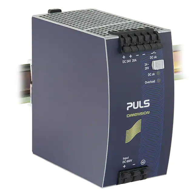
QTD20.241
24V, 20A, DC INPUT
Q-Series
DC/DC CONVERTER
▪
▪
▪
▪
▪
▪
▪
▪
▪
▪
▪
▪
▪
DC 600V Input
Optimized for Intermediate DC-bus of Drive Systems
Two Input Fuses for DC 600V included
95% Full Load and Excellent Partial Load Efficiencies
Width only 65mm, Weight only 890g
25% BonusPower, 600W for up to 4s
Active Filtering of Input Transients
Full Power Between -25°C and +60°C
Extremely Low Input Inrush Current Surge
Reverse Input Polarity Protection
DC-OK Relay Contact
Quick-connect Spring-clamp Terminals
3 Year Warranty
PRODUCT DESCRIPTION
SHORT-FORM DATA
Modern machines typically use maintenance-free AC-motors
which are controlled by frequency converters or servo
amplifiers. Such devices have an intermediate DC-bus where all
individual drives are connected.
The QTD20 DC/DC converter can be connected directly to the
intermediate DC-bus. In case of a mains failure, the QTD20
utilizes the power from the DC-bus capacitors which are
charged from the kinetic energy of the motor until the motor
has come to a complete stop.
Output voltage
Adjustment range
Output current
The intermediate DC-bus is usually unfiltered and have high
EMI noise so the QTD20 has a very robust input stage and an
appropriate input filter included. Additionally, the QTD20 is UL
508 approved and is equipped with input fuses which are rated
and
tested
for
600Vdc applications.
L1
f
+
L2
L3
PE
Motor
f
PE
+ QTD
+
PE
Motor
DC Load,
Controller
QTD20.241
Accessory
ZM1.WALL
ZM14.SIDE
UF20.241
YR40.241
Output ripple
Input voltage
Input current
Inrush current
Efficiency
Losses
Temperature range
Derating
Hold-up time
Dimensions
Weight
nominal
continuous
short term (4s)
continuous
short term (4s)
20Hz to 20MHz
-20%/+40%
at 600Vdc
at 600Vdc
at 600Vdc
operational
+60 to +70°C
at 600Vdc
WxHxD
MAIN APPROVALS
ORDER NUMBERS
DC/DC converter
Output power
DC 24V
24 - 28V
20 – 17.5A
25 – 21.4A
480W
600W
< 100mVpp
DC 600V
0.85A
typ. 1.5A peak
95.0%
25.5W
-25°C to +70°C
12W/°C
typ. 22ms
65x124x127mm
890g
For details and the complete approval list, see chapter 19.
Wall mount bracket
Side mount bracket
Buffer unit
Redundancy module
UL 508
Oct. 2022 / Rev. 2.3 DS-QTD20.241-EN
All parameters are specified at 24V, 20A, 600Vdc input, 25°C ambient and after a 5 minutes run-in time unless otherwise noted.
www.pulspower.com Phone +49 89 9278 0 Germany
1/29
�QTD20.241
24V, 20A, DC INPUT
Q-Series
INDEX
Page
1.
2.
3.
4.
5.
6.
7.
8.
9.
10.
11.
12.
13.
14.
15.
16.
17.
18.
19.
20.
Intended Use ................................................................ 3
Installation Instructions ................................................ 3
Input ............................................................................. 5
Input Inrush Current ..................................................... 6
Output .......................................................................... 7
Hold-up Time ................................................................ 9
DC-OK Relay Contact .................................................... 9
Efficiency and Power Losses ....................................... 10
Lifetime Expectancy ................................................... 11
MTBF .......................................................................... 11
Functional Diagram .................................................... 12
Terminals and Wiring ................................................. 13
Front Side and User Elements .................................... 14
EMC ............................................................................ 15
Environment ............................................................... 16
Protection Features .................................................... 17
Safety Features........................................................... 17
Dielectric Strength ...................................................... 18
Approved, Fulfilled or Tested Standards .................... 19
Regulatory Product Compliance ................................. 19
Page
21. Physical Dimensions and Weight ............................... 20
22. Accessories................................................................. 21
22.1. ZM1.WALL – Wall/Panel mounting .................. 21
22.2. ZM14.SIDE - Side Mounting Bracket................. 21
22.3. UF20.241 - Buffer module ................................ 22
22.4. YR40.241 - Redundancy Module ...................... 22
23. Application Notes....................................................... 23
23.1. Repetitive Pulse Loading .................................. 23
23.2. Peak Current Capability .................................... 24
23.3. External Input Protection ................................. 24
23.4. Charging of Batteries ........................................ 25
23.5. Output Circuit Breakers .................................... 26
23.6. Series Operation............................................... 26
23.7. Parallel Use to Increase Output Power ............ 27
23.8. Parallel Use for Redundancy ............................ 27
23.9. Inductive and Capacitive Loads ........................ 27
23.10. Back-feeding Loads .......................................... 28
23.11. Use in a Tightly Sealed Enclosure ..................... 28
23.12. Mounting Orientations ..................................... 29
The information given in this document is correct to the best of our knowledge and experience at the time of publication. If not expressly agreed
otherwise, this information does not represent a warranty in the legal sense of the word. As the state of our knowledge and experience is constantly
changing, the information in this data sheet is subject to revision. We therefore kindly ask you to always use the latest issue of this document (available
under www.pulspower.com). No part of this document may be reproduced or utilized in any form without our prior permission in writing.
Some parts of this unit are patent by PULS (US patent No 091662,063, Des. 424,529, …).
TERMINOLOGY AND ABREVIATIONS
PE and
symbol
PE is the abbreviation for Protective Earth and has the same meaning as the symbol
.
Earth, Ground
This document uses the term “earth” which is the same as the U.S. term “ground”.
t.b.d.
To be defined, value or description will follow later.
DC 600V
A figure displayed with the AC or DC before the value represents a nominal voltage with standard tolerances
included.
E.g.: DC 12V describes a 12V battery disregarding whether it is full (13.7V) or flat (10V)
600Vdc
A figure with the unit (Vac or Vdc) at the end is a momentary figure without any additional tolerances
included.
may
A key word indicating flexibility of choice with no implied preference.
shall
A key word indicating a mandatory requirement.
should
A key word indicating flexibility of choice with a strongly preferred implementation.
Oct. 2022 / Rev. 2.3 DS-QTD20.241-EN
All parameters are specified at 24V, 20A, 600Vdc input, 25°C ambient and after a 5 minutes run-in time unless otherwise noted.
www.pulspower.com Phone +49 89 9278 0 Germany
2/29
�QTD20.241
24V, 20A, DC INPUT
Q-Series
1. INTENDED USE
This device is designed for installation in an enclosure and is intended for commercial use, such as in industrial control, process control,
monitoring and measurement equipment or the like.
This device is optimized to operate from the intermediate bus of a drive system. It can cope with the EMI disturbances on such busses.
Do not use this device in equipment, where malfunctioning may cause severe personal injury or threaten human life without additional
appropriate safety devices, that are suited for the end-application.
If this device is used in a manner outside of its specification, the protection provided by the device may be impaired.
2. INSTALLATION INSTRUCTIONS
WARNING
-
Risk of electrical shock, fire, personal injury or death.
Turn power off before working on the device and protect against inadvertent re-powering.
Do not open, modify or repair the device.
Use caution to prevent any foreign objects from entering into the housing.
Do not use in wet locations or in areas where moisture or condensation can be expected.
Do not touch during power-on, and immediately after power-off. Hot surface may cause burns.
Obey the following installation instructions:
This device may only be installed and put into operation by qualified personnel.
This device does not contain serviceable parts. The tripping of an internal fuse is caused by an internal defect.
If damage or malfunction should occur during installation or operation, immediately turn power off and send unit to the factory for
inspection.
Install device in an enclosure providing protection against electrical, mechanical and fire hazards.
Install the device onto a DIN rail according to EN 60715 with the input terminals on the bottom of the device. Other mounting
orientations require a reduction in output current.
Make sure that the wiring is correct by following all local and national codes. Use appropriate copper cables that are designed for a
minimum operating temperature of 60°C for ambient temperatures up to +45°C, 75°C for ambient temperatures up to +60°C and 90°C
for ambient temperatures up to +70°C.
Ensure that all strands of a stranded wire enter the terminal connection. Use ferrules for wires on the input terminals.
The device is designed for pollution degree 2 areas in controlled environments. No condensation or frost is allowed.
The enclosure of the device provides a degree of protection of IP20. The enclosure does not provide protection against spilled liquids.
The isolation of the devices is designed to withstand impulse voltages up to 4kV according to IEC 60664-1.
The device is designed as “Class of Protection I” equipment according to IEC 61140. Do not use without a proper PE (Protective Earth)
connection.
The device is designed to be supplied from a DC input voltage derived from a 3-phase mains network by means of a B6 bridge rectifier.
The device is not designed to be used on corner grounded delta systems. Follow the wiring scheme option 1 shown in this document.
The input can also be supplied by batteries or similar DC sources. Since the continuous voltage between the input voltage and the
PE/earth potential must not exceed 440V r.m.s., the input voltage must be grounded at about half the supply voltage as shown in option
2 in the wiring scheme drawing. Do not ground the positive or negative input voltage pole.
Check for correct input polarity. The device will not operate when the voltage is reversed.
A disconnecting means shall be provided for the input of the device. The device is designed for convection cooling and does not require
an external fan. Do not obstruct airflow and do not cover ventilation grid!
The device is designed for altitudes up to 5000m.
Oct. 2022 / Rev. 2.3 DS-QTD20.241-EN
All parameters are specified at 24V, 20A, 600Vdc input, 25°C ambient and after a 5 minutes run-in time unless otherwise noted.
www.pulspower.com Phone +49 89 9278 0 Germany
3/29
�QTD20.241
24V, 20A, DC INPUT
Q-Series
Keep the following minimum installation clearances: 40mm on top, 20mm on the bottom, 5mm left and right side. Increase the 5mm to
15mm in case the adjacent device is a heat source. When the device is permanently loaded with less than 50%, the 5mm can be reduced
to zero.
The device is designed, tested and approved for branch circuits up to 16A (IEC) and 15A (UL) without additional protection device. If an
external fuse is utilized, do not use circuit breakers smaller than 6A B- or 3A C-Characteristic to avoid a nuisance tripping of the circuit
breaker.
The maximum surrounding air temperature is +70°C. The operational temperature is the same as the ambient or surrounding air
temperature and is defined 2cm below the device.
The device is designed to operate in areas between 5% and 95% relative humidity.
Oct. 2022 / Rev. 2.3 DS-QTD20.241-EN
All parameters are specified at 24V, 20A, 600Vdc input, 25°C ambient and after a 5 minutes run-in time unless otherwise noted.
www.pulspower.com Phone +49 89 9278 0 Germany
4/29
�QTD20.241
24V, 20A, DC INPUT
Q-Series
3. INPUT
Input
Input range
max.
DC 600V -20%/+40%
480-840Vdc
360-480Vdc
840-900Vdc
1000Vdc
max.
max.
max.
600V R.M.S.
±900Vpk
1000V/µs
max.
typ.
typ.
typ.
typ.
typ.
typ.
max.
50Vpp
50Hz-40kHz
450Vdc
Steady-state value, load independent, see Fig. 3-1
325Vdc
Steady-state value, load independent, see Fig. 3-1
0.79A
At 24V, 20A, see Fig. 3-3
350ms
See Fig. 3-2
70ms
At 24V, 20A, only resistive load see Fig. 3-2
110ms
At 24V, 20A, resistive load with an additional 20mF capacitor
500mV
See Fig. 3-2
Allowed without any limitations
nom.
Allowed voltage input to Earth
Slew rate for voltages between input
and Earth (ground)
Allowed input ripple voltage
Turn-on voltage
Shut-down voltage
Input current
Start-up delay
Rise time
Turn-on overshoot
External capacitors on input
Max. 60s or with reduced output current, see Fig. 5-2
Max. 60s or with reduced output current, see Fig. 5-2
Absolute maximum input voltage with no damage to the DC/DC
converter. Above 900Vdc, the output will switch off and will
turn-on again, when the input voltage falls below 850Vdc.
Continuous, IEC 60664-1
Peak value, allowed for transients
Fig. 3-1 Input voltage range
POUT
B
A
Turn-on
Shut-down
B
A: Input Range
B: < 60s or with derating
900Vdc
840Vdc
450Vdc
480Vdc
325Vdc
360Vdc
VIN
QTD20.241
Fig. 3-2 Turn-on behavior, definitions
Fig. 3-3 Input current vs. output load at 24V
Input Current, typ.
Intput
Voltage
1.0A
0.8
Output
Voltage
- 5%
Start-up
delay
Rise
Time
Overshoot
0.6
0.4
0.2
Output Current
0
2
4
6
8 10 12 14 16 18 20A
Oct. 2022 / Rev. 2.3 DS-QTD20.241-EN
All parameters are specified at 24V, 20A, 600Vdc input, 25°C ambient and after a 5 minutes run-in time unless otherwise noted.
www.pulspower.com Phone +49 89 9278 0 Germany
5/29
�QTD20.241
24V, 20A, DC INPUT
Q-Series
4. INPUT INRUSH CURRENT
The DC/DC converter is equipped with an active inrush current limitation circuit, which limits the input inrush current after turn-on and
after short input voltage interruptions to a very low value.
Inrush
current*)
Inrush energy
Inrush delay
*)
DC 600V
3Apeak
1.6Apeak
1A2s
350ms
max.
typ.
max.
typ.
Over entire temperature range
Over entire temperature range
Over entire temperature range
The charging current into EMI suppression capacitors is disregarded in the first microseconds after switch-on.
Fig. 4-1 Typical turn-on behavior at nominal load and
25°C ambient temperature
Input Voltage
Output Voltage
Input Current
Input:
Output:
Ambient:
600Vdc
24V, 20A
25°C
Upper curve:
Medium curve:
Lower curve:
Time base:
Input voltage 100V/Div
Output voltage 5V/DIV
Input current 1A/DIV
100ms/DIV
Oct. 2022 / Rev. 2.3 DS-QTD20.241-EN
All parameters are specified at 24V, 20A, 600Vdc input, 25°C ambient and after a 5 minutes run-in time unless otherwise noted.
www.pulspower.com Phone +49 89 9278 0 Germany
6/29
�QTD20.241
24V, 20A, DC INPUT
Q-Series
5. OUTPUT
Output voltage
Adjustment range
Factory setting
Line regulation
Load regulation
Ripple and noise voltage
Output current – continuous
Output current – up to 4s 1)
Output power – continuous
Output power – up to 4s 1)
BonusPower time
BonusPower recovery time
Overload behavior
Short-circuit current 2)
Output capacitance
nom.
max.
typ.
max.
max.
max.
nom.
nom.
nom.
nom.
nom.
nom.
typ.
typ.
24V
24-28V
30V 3)
24.1V
10mV
100mV
100mVpp
20A 4)
17.5A 4)
25A
21.4A
480W
600W
4s
7s
Guaranteed
At clockwise end position of potentiometer
±0.2%, at full load, cold unit
At 480-840Vdc voltage change
Static value, 0A→20A
20Hz to 20MHz, 50Ohm
At 24V, input: 480-840Vdc, see Fig. 5-1
At 28V, input: 480-840Vdc, see Fig. 5-1
At 24V, input: 480-840Vdc, see Fig. 5-1 and Fig. 5-3
At 28V, input: 480-840Vdc, see Fig. 5-1 and Fig. 5-3
At 24-28V
At 24-28V
Duration until the output voltage dips, see Fig. 5-3
Overload free time to reset power manager, see Fig. 5-4
min.
max.
min.
max.
typ.
cont. current
20A
23A
25A
28A
950µF
See Fig. 5-1
Continuous, load impedance 50mOhm, see Fig. 5-1
Continuous, load impedance 50mOhm, see Fig. 5-1
Short-term (4s), load impedance 50mOhm, see Fig. 5-1
Short-term (4s), load impedance 50mOhm, see Fig. 5-1
Included in the DC/DC converter
1)
BonusPower, short term power capability (up to typ. 4s)
The DC/DC converter is designed to support loads with a higher short-term power requirement without damage or shutdown. The short-term duration is
hardware controlled by an output power manager. This BonusPower is repeatedly available. Detailed information can be found in chapter 23.1. If the
DC/DC converter is loaded longer with the BonusPower than shown in the bonus-time diagram (see Fig. 5-3), the max. output power is automatically
reduced to 480W.
2)
Discharge current of output capacitors is not included.
3)
This is the maximum output voltage which can occur at the clockwise end position of the potentiometer due to tolerances. It is not guaranteed value
which can be achieved. The typical value is about 28.5V.
4)
Reduce output current according to Fig. 5-2 for the extended input voltage ranges from 360-480Vdc and 840-900Vdc.
Oct. 2022 / Rev. 2.3 DS-QTD20.241-EN
All parameters are specified at 24V, 20A, 600Vdc input, 25°C ambient and after a 5 minutes run-in time unless otherwise noted.
www.pulspower.com Phone +49 89 9278 0 Germany
7/29
�QTD20.241
24V, 20A, DC INPUT
Q-Series
Fig. 5-1 Output voltage vs. output current, typ.
Adjustment
Range
Output Voltage
28V
Fig. 5-2 Output current vs. input voltage
Allowed Output
Current at 24V
25A
20
20
continuous
short -t erm
24
16
12
8
4
0
Output Current
0
5
10
15
20
25 30A
f or t yp. 4s
continuous
3.5mm
E.g. screws, small parts
yes
Output shut-down with automatic restart
MOV (Metal Oxide Varistor)
included
The unit is equipped with two internal input fuses (+ line and line) which protect the unit against internal short circuits and
ground faults. The fuses are not user accessible. A tripping of an
internal fuse is caused by an internal fault.
In case of a protection event, audible noise may occur.
17. SAFETY FEATURES
Input / output separation*)
Class of protection
Isolation resistance
PE resistance
Touch current (leakage current)
*)
SELV
EN 62477-1
PELV
IEC/EN 60204-1, EN 62477-1, IEC 62103, IEC 60364-4-41
I
PE (Protective Earth) connection required
> 500MOhm
Input to output, 500Vdc
< 0.1Ohm
The leakage current, which is produced by the DC/DC converter itself, depends on the input
voltage ripple and need to be investigated in the final application.
For a smooth DC input voltage, the produced leakage current is less than 100µA.
double or reinforced insulation
Oct. 2022 / Rev. 2.3 DS-QTD20.241-EN
All parameters are specified at 24V, 20A, 600Vdc input, 25°C ambient and after a 5 minutes run-in time unless otherwise noted.
www.pulspower.com Phone +49 89 9278 0 Germany
17/29
�QTD20.241
24V, 20A, DC INPUT
Q-Series
18. DIELECTRIC STRENGTH
The output voltage is floating and has no ohmic connection to the ground. Type and factory tests are conducted by the manufacturer.
Field tests may be conducted in the field using the appropriate test equipment which applies the voltage with a slow ramp (2s up and 2s
down). Connect all input poles together as well as all output poles before conducting the test. When testing, set the cut-off current
settings to the value in the table below.
Type test
60s
A
2500Vac
B
3000Vac
C
500Vac
D
500Vac
Factory test
5s
2500Vac
2500Vac
500Vac
500Vac
Field test
5s
2000Vac
2000Vac
500Vac
500Vac
Cut-off current setting
> 10mA
> 10mA
> 30mA
> 1mA
Fig. 18-1 Dielectric strength
Input
+
DC-ok
B* )
-
B
A
D
Output
Earth
C
+
-
To fulfil the PELV requirements according to EN 60204-1 § 6.4.1, we
recommend that either the + pole, the – pole or any other part of the output
circuit shall be connected to the protective earth system. This helps to avoid
situations in which a load starts unexpectedly or can not be switched off
when unnoticed earth faults occur.
B*) When testing input to DC-OK ensure that the max. voltage between DC-OK and the output is not exceeded (column D). We recommend connecting DC-OK
pins and the output pins together when performing the test.
Oct. 2022 / Rev. 2.3 DS-QTD20.241-EN
All parameters are specified at 24V, 20A, 600Vdc input, 25°C ambient and after a 5 minutes run-in time unless otherwise noted.
www.pulspower.com Phone +49 89 9278 0 Germany
18/29
�QTD20.241
24V, 20A, DC INPUT
Q-Series
19. APPROVED, FULFILLED OR TESTED STANDARDS
UL 508
UL Certificate
Listed equipment for category NMTR - Industrial Control Equipment
Applicable for US and Canada
E-File: E198865
IEC 61010-2-201
Agency Certificate
Electrical Equipment for Measurement, Control and Laboratory Use Particular requirements for control equipment
VDMA 24364
Paint Wetting Impairment Substances Test (or LABS-Test)
Tested for Zone 2 and test class C1 according to VDMA 24364-C1-L/W for
solvents and water-based paints
20. REGULATORY PRODUCT COMPLIANCE
EU Declaration of Conformity
REACH Regulation (EU)
WEEE Regulation
The CE mark indicates conformance with the
- EMC directive
- LVD directive
Manufacturer's Declaration
EU regulation regarding the Registration, Evaluation, Authorisation
and Restriction of Chemicals (REACH) fulfilled.
EU Regulation (EC) 1907/2006.
Manufacturer's Declaration
EU Regulation on Waste Electrical and Electronic Equipment
Registered as business to business (B2B) products.
EU Regulation 2012/19/EU
KC Certification
The KC mark indicate registered under the Clause 3, Article 58-2
of Radio Waves Art of the Republic of Korea
EAC TR Registration
EAC Certificate
EAC EurAsian Conformity - Registration Russia, Kazakhstan and
Belarus
8504408200, 8504409000
Oct. 2022 / Rev. 2.3 DS-QTD20.241-EN
All parameters are specified at 24V, 20A, 600Vdc input, 25°C ambient and after a 5 minutes run-in time unless otherwise noted.
www.pulspower.com Phone +49 89 9278 0 Germany
19/29
�QTD20.241
24V, 20A, DC INPUT
Q-Series
21. PHYSICAL DIMENSIONS AND WEIGHT
Width
Height
Depth
Weight
DIN rail
Housing material
Installation clearances
65mm
124mm
127mm
The DIN rail depth must be added to the unit depth to calculate the total required installation depth.
890g
Use 35mm DIN rails according to EN 60715 or EN 50022 with a height of 7.5 or 15mm.
Body: Aluminium alloy
Cover: Zinc-plated steel
See chapter 2
Fig. 21-1 Front view
Fig. 21-2 Side view
Oct. 2022 / Rev. 2.3 DS-QTD20.241-EN
All parameters are specified at 24V, 20A, 600Vdc input, 25°C ambient and after a 5 minutes run-in time unless otherwise noted.
www.pulspower.com Phone +49 89 9278 0 Germany
20/29
�QTD20.241
24V, 20A, DC INPUT
Q-Series
22. ACCESSORIES
22.1. ZM1.WALL – WALL/PANEL MOUNTING
This bracket is used to mount the QTD20 DC/DC converter on a wall/panel without utilizing a DIN rail.
The two aluminum brackets and the black plastic slider of the unit have to be detached, so that the steel brackets can be mounted.
Fig. 22-1 Wall/panel mounting
Fig. 22-2 Wall/panel mounting
Fig. 22-3 Mounting Dimensions - Wall mounting
bracket
22.2. ZM14.SIDE - SIDE MOUNTING BRACKET
This bracket is used to mount the QTD20 DC/DC converter sideways with or without utilizing a DIN rail.
The two aluminum brackets and the black plastic slider of the unit have to be detached, so that the steel brackets can be mounted.
For sideway DIN rail mounting, the removed aluminum brackets and the black plastic slider need to be mounted on the steel bracket.
Fig. 22-4
Side mounting without DIN rail
brackets
Fig. 22-5
Side mounting with DIN rail
brackets
Fig. 22-6
Mounting Dimensions
Side mounting bracket
Oct. 2022 / Rev. 2.3 DS-QTD20.241-EN
All parameters are specified at 24V, 20A, 600Vdc input, 25°C ambient and after a 5 minutes run-in time unless otherwise noted.
www.pulspower.com Phone +49 89 9278 0 Germany
21/29
�QTD20.241
24V, 20A, DC INPUT
Q-Series
22.3. UF20.241 - BUFFER MODULE
This buffer unit is a supplementary device for DC 24V power supplies and DC/DC converter. It
delivers power to bridge typical mains failures or extends the hold-up time after turn-off of the
AC or DC power. In times when the DC/DC converter provides sufficient voltages, the buffer
unit stores energy in the integrated electrolytic capacitors. In case of mains voltage fault, this
energy is released again in a regulated process.
The buffer unit does not require any control wiring. It
can be added in parallel to the load circuit at any
given point. Buffer units can be added in parallel to
increase the output ampacity or the hold-up time.
AC
Power
Supply
Buffer
Unit(s)
Load
+
-
DC
22.4. YR40.241 - REDUNDANCY MODULE
The YR40.241 redundancy module is equipped with two input channels (20A each), which are
individually decoupled by utilizing MOSFET technology. The output current can go as high as
40A.
Using MOSFET instead of diodes reduces the heat generation and the voltage drop between
input and output. The YR40.241 does not require an additional auxiliary voltage and is selfpowered even in case of a short circuit across the output.
Due to the low power losses, the unit is very slender and only requires 36mm width on the DIN
rail.
Fig. 22-7 Typical 1+1 Redundant configuration for 20A with
one dual redundancy module und two DC/DC converters
Fig. 22-8 Typical N+1 Redundant configuration for 60A with two dual redundancy modules and
four DC/DC converters
Failure
Monitor
Failure
Monitor
++
+ - + -
--
DC24V,20A OK
QTD20.241
+
-
Input Input
2
1
YR40.241
Redundancy
Module
++
+
+ -
-
+ - + -
--
DC24V,20A OK
QTD20.241
QTD20.241
Output
PE
++
--
DC24V,20A OK
+
PE
-
Input Input
2
1
YR40.241
Redundancy
Module
++
QTD20.241
Output
PE
--
DC24V,20A OK
+
+ -
-
++
+ - + -
--
DC24V,20A OK
QTD20.241
+
PE
-
PE
Input Input
2
1
YR40.241
Redundancy
Module
++
QTD20.241
Output
+
+ -
20A
Load
I
--
DC24V,20A OK
-
PE
60A
Load
I
I
+
+
-
-
PE
PE
I
I
Oct. 2022 / Rev. 2.3 DS-QTD20.241-EN
All parameters are specified at 24V, 20A, 600Vdc input, 25°C ambient and after a 5 minutes run-in time unless otherwise noted.
www.pulspower.com Phone +49 89 9278 0 Germany
I
22/29
�QTD20.241
24V, 20A, DC INPUT
Q-Series
23. APPLICATION NOTES
23.1. REPETITIVE PULSE LOADING
Typically, a load current is not constant and varies over time. This DC/DC converter is designed to support loads with a higher short-term
power demand (=BonusPower). The short-term duration is hardware controlled by an output power manager and is available on a
repeated basis. If the BonusPower load lasts longer than the hardware controller allows it, the output voltage will dip and the next
BonusPower is available after the BonusPower recovery time (see chapter 5) has elapsed.
To avoid this, the following rules must be met:
a)
The power demand of the pulse must be below 125% of the nominal output power.
b)
The duration of the pulse power must be shorter than the allowed BonusPower time. (see output chapter)
c)
The average (R.M.S.) output current must be below the specified continuous output current.
If the R.M.S. current is higher, the unit will respond with a thermal shut-down after a period of time. Use the maximum duty cycle
curve (Fig. 23-2) to check if the average output current is below the nominal current.
d)
The duty cycle must be below 0.75.
Fig. 23-1 Repetitive pulse loads, definitions
Fig. 23-2 Max. duty cycle curve
P0 = 10%
P0 = 50%
P0 = 75%
Duty Cycle
PPEAK TPEAK
T0
0.75
max.
125%
0.6
100%
0.4
P0 = 100%
0.2
P0
PPEAK
0
100
P0
PPEAK
T0
TPEAK
Example:
Base load (W)
Pulse load (above 100%)
Duration between pulses (s)
Pulse duration (s)
105
DutyCycle =
T0 =
110
115
120
125%
Tpeak
Tpeak + T0
Tpeak - (DutyCycle x Tpeak)
DutyCycle
A load is powered continuously with 240W (= 50% of the rated output load). From time to time a peak power of 600W (=
125% of the rated output load) is needed for 1 second.
The question is: How often can this pulse be supplied without overloading the DC/DC converter?
- Make a vertical line at PPEAK = 125% and a horizontal line where the vertical line crosses the P0 = 50% curve. Read the
max. duty cycle from the duty cycle-axis (= 0.37)
- Calculate the required pause (base load) length T0:
- Result: The required pause length = 1.7s
T0=
Tpeak - (DutyCycle x Tpeak)
- Max. repetition rate = pulse +pause length = 2.7s
DutyCycle
=
1s- (0.37 x 1s)
0.37
=1.7s
More examples for pulse load compatibility:
PPEAK
600W
600W
540W
P0
480W
0W
240W
TPEAK
1s
1s
1s
T0
>25s
>1.3s
> 0.75s
PPEAK
600W
600W
600W
P0
240W
240W
240W
TPEAK
0.1s
1s
3s
T0
>0.16s
>1.6s
>4.9s
Oct. 2022 / Rev. 2.3 DS-QTD20.241-EN
All parameters are specified at 24V, 20A, 600Vdc input, 25°C ambient and after a 5 minutes run-in time unless otherwise noted.
www.pulspower.com Phone +49 89 9278 0 Germany
23/29
�QTD20.241
24V, 20A, DC INPUT
Q-Series
23.2. PEAK CURRENT CAPABILITY
The DC/DC converter can deliver peak currents (up to several milliseconds) which are higher than the specified short term currents.
This helps to start current demanding loads. Solenoids, contactors and pneumatic modules often have a steady state coil and a pick-up
coil. The inrush current demand of the pick-up coil is several times higher than the steady-state current and usually exceeds the nominal
output current (including the BonusPower). The same situation applies when starting a capacitive load.
The peak current capability also ensures the safe operation of subsequent circuit breakers of load circuits. The load branches are often
individually protected with circuit breakers or fuses. In case of a short or an overload in one branch circuit, the fuse or circuit breaker
need a certain amount of over-current to open in a timely manner. This avoids voltage loss in adjacent circuits.
The extra current (peak current) is supplied by the power converter and the built-in large sized output capacitors of the DC/DC
converter. The capacitors get discharged during such an event, which causes a voltage dip on the output. The following two examples
show typical voltage dips:
Fig. 23-3 Peak load with 2x the nominal current for 50ms,
typ.
Fig. 23-4 Peak load with 5x the nominal current for 5ms,
typ.
Output
Voltage
24V
Output
Voltage
24V
100A
40A
4V
13V
Output
Current
0A
Output
Current
0A
10ms/DIV
1ms/DIV
40A Peak load (resistive) for 50ms
Output voltage dips from 24V to 13V.
100A Peak load (resistive) for 5ms
Output voltage dips from 24V to 4V.
Please note: The DC-OK relay triggers when the voltage dips more than 10% for longer than 1ms.
Peak current voltage dips
typ.
typ.
typ.
from 24V to 13V
from 24V to 4V
from 24V to 4V
At 40A for 50ms, resistive load
At 80A for 2ms, resistive load
At 80A for 5ms, resistive load
23.3. EXTERNAL INPUT PROTECTION
The unit is tested and approved for branch circuits up to 15A (U.S.A.) and 16A (IEC). An external protection is only required if the
supplying branch has an ampacity greater than this. Check also local codes and local requirements. In some countries local regulations
might apply.
If an external fuse is necessary or utilized, minimum requirements need to be considered to avoid nuisance tripping of the circuit
breaker. A minimum value of 6A B- or 3A C-Characteristic breaker should be chosen.
Oct. 2022 / Rev. 2.3 DS-QTD20.241-EN
All parameters are specified at 24V, 20A, 600Vdc input, 25°C ambient and after a 5 minutes run-in time unless otherwise noted.
www.pulspower.com Phone +49 89 9278 0 Germany
24/29
�QTD20.241
24V, 20A, DC INPUT
Q-Series
23.4. CHARGING OF BATTERIES
The DC/DC converter can be used to charge lead-acid or maintenance free batteries. (Two 12V batteries in series)
Instructions for charging batteries:
a)
Set output voltage (measured at no load and at the battery end of the cable) very precisely to the end-of-charge voltage.
End-of-charge voltage
27.8V
27.5V
27.15V
26.8V
Battery temperature
10°C
20°C
30°C
40°C
b)
Use a 25A circuit breaker (or blocking diode) between the DC/DC converter and the battery.
c)
Ensure that the output current of the DC/DC converter is below the allowed charging current of the battery.
d)
Use only matched batteries when putting 12V types in series.
e)
The return current to the DC/DC converter (battery discharge current) is typ. 16mA when the DC/DC converter is switched off
(except in case a blocking diode is utilized).
Oct. 2022 / Rev. 2.3 DS-QTD20.241-EN
All parameters are specified at 24V, 20A, 600Vdc input, 25°C ambient and after a 5 minutes run-in time unless otherwise noted.
www.pulspower.com Phone +49 89 9278 0 Germany
25/29
�QTD20.241
24V, 20A, DC INPUT
Q-Series
23.5. OUTPUT CIRCUIT BREAKERS
Standard miniature circuit breakers (MCB’s or UL1077 circuit breakers) are commonly used for AC-supply systems and may also be used
on DC branches.
MCB’s are designed to protect wires and circuits. If the ampere value and the characteristics of the MCB are adapted to the wire size
that is used, the wiring is considered as thermally safe regardless of whether the MCB opens or not.
To avoid voltage dips and under-voltage situations in adjacent 24V branches which are supplied by the same source, a fast (magnetic)
tripping of the MCB is desired. A quick shutdown within 10ms is necessary corresponding roughly to the ride-through time of PLC's. This
requires power supplies with high current reserves and large output capacitors. Furthermore, the impedance of the faulty branch must
be sufficiently small in order for the current to actually flow. The best current reserve in the DC/DC converter does not help if Ohm’s law
does not permit current flow. The following table has typical test results showing which B- and C-Characteristic MCBs magnetically trip
depending on the wire cross section and wire length.
Fig. 23-5 Test circuit
Power Supply
AC
MCB
+
+
Wire length
DC S1... Fault simulation switch
*)
Load
S1
Maximal wire length*) for a fast (magnetic) tripping:
0.75mm²
1.0mm²
1.5mm²
C-2A
31m
39m
59m
2.5mm²
86m
C-3A
C-4A
C-6A
24m
15m
-
31m
15m
-
43m
32m
-
68m
41m
-
B-6A
16m
25m
34m
58m
B-10A
-
-
-
-
-
Don’t forget to consider twice the distance to the load (or cable length) when calculating the total wire length (+ and – wire).
23.6. SERIES OPERATION
DC/DC converters of the same type can be connected in series for higher output voltages. It
is possible to connect as many units in series as needed, providing the sum of the output
voltage does not exceed 150Vdc. Voltages with a potential above 60Vdc are not SELV any
more and can be dangerous. Such voltages must be installed with a protection against
touching.
Avoid return voltage (e.g. from a decelerating motor or battery) which is applied to the
output terminals.
Unit A
Input
Output
+
+
Unit B
Keep an installation clearance of 15mm (left / right) between two power supplies and avoid
installing the power supplies on top of each other. Do not use power supplies in series in
mounting orientations other than the standard mounting orientation (input terminals on the
bottom of the unit).
Load
Input
Output
+
-
-
Pay attention that leakage current, EMI, inrush current, harmonics will increase when using multiple DC/DC converters.
Oct. 2022 / Rev. 2.3 DS-QTD20.241-EN
All parameters are specified at 24V, 20A, 600Vdc input, 25°C ambient and after a 5 minutes run-in time unless otherwise noted.
www.pulspower.com Phone +49 89 9278 0 Germany
26/29
�QTD20.241
24V, 20A, DC INPUT
Q-Series
23.7. PARALLEL USE TO INCREASE OUTPUT POWER
DC/DC converters and power supplies from the same series (Q-Series) can be paralleled to increase the output power. The output
Unit A
voltage shall be adjusted to the same value (±100mV) or the units can be left with the
Input
factory settings.
If more than three units are connected in parallel, a fuse or circuit breaker with a rating of
25A is required on each output. Alternatively, a diode or redundancy module can also be
utilized.
Keep an installation clearance of 15mm (left / right) between two power supplies and
avoid installing the DC/DC converters or power supplies on top of each other. Do not use
DC/DC converters or power supplies in parallel in mounting orientations other than the
standard mounting orientation (input terminals on the bottom of the unit) or in any other
condition where a derating of the output current is required (e.g. altitude, above 60°C, …).
+
-
Output
+
Unit B
Load
Input
+
-
-
Output
Pay attention that leakage current, EMI, inrush current, harmonics will increase when using multiple DC/DC converters.
23.8. PARALLEL USE FOR REDUNDANCY
DC/DC converters can be paralleled for redundancy to gain higher system availability. Redundant systems require a certain amount of
extra power to support the load in case one DC/DC converter unit fails. The simplest way is to connect two DC/DC converters in parallel.
This is called a 1+1 redundancy. In case one DC/DC converter unit fails, the other one is automatically able to support the load current
without any interruption. Redundant systems for a higher power demand are usually built in a N+1 method. E.g. five DC/DC converters,
each rated for 20A are paralleled to build a 80A redundant system. For N+1 redundancy the same restrictions apply as for increasing the
output power, see also chapter 23.7.
Please note: This simple way to build a redundant system does not cover failures such as an internal short circuit in the secondary side
of the DC/DC converter. In such a case, the defective unit becomes a load for the other power supplies and the output voltage can not
be maintained any more. This can be avoided by utilizing redundancy modules, which have decoupling devices (diodes or MOSFETs)
included. Further information and wiring configurations can be found in chapter 22.4.
Recommendations for building redundant power systems:
a)
b)
c)
Use separate input fuses for each DC/DC converter. A separate source for each supply when possible increases the reliability of the
redundant system.
Monitor the individual DC/DC converter units. Therefore, use the DC-OK relay contact of the QTD20.241.
It is desirable to set the output voltages of all units to the same value (± 100mV) or leave it at the factory setting.
23.9. INDUCTIVE AND CAPACITIVE LOADS
The unit is designed to supply any kind of loads, including capacitive and inductive loads.
Oct. 2022 / Rev. 2.3 DS-QTD20.241-EN
All parameters are specified at 24V, 20A, 600Vdc input, 25°C ambient and after a 5 minutes run-in time unless otherwise noted.
www.pulspower.com Phone +49 89 9278 0 Germany
27/29
�QTD20.241
24V, 20A, DC INPUT
Q-Series
23.10. BACK-FEEDING LOADS
Loads such as decelerating motors and inductors can feed voltage back to the DC/DC converter. This feature is also called return voltage
immunity or resistance against Back- E.M.F. (Electro Magnetic Force).
This DC/DC converter is resistant and does not show malfunctioning when a load feeds back voltage to the DC/DC converter. It does not
matter whether the DC/DC converter is on or off.
The maximum allowed feed-back-voltage is 34Vdc. The absorbing energy can be calculated according to the built-in output capacitor
which is specified in chapter 5.
23.11. USE IN A TIGHTLY SEALED ENCLOSURE
When the DC/DC converter is installed in a tightly sealed enclosure, the temperature inside the enclosure will be higher than outside. In
such situations, the inside temperature defines the ambient temperature for the DC/DC converter.
The following measurement results can be used as a reference to estimate the temperature rise inside the enclosure.
The DC/DC converter is placed in the middle of the box, no other heat producing items are inside the box
Enclosure:
Load:
Input:
Temperature inside enclosure:
Temperature outside enclosure:
Temperature rise:
Rittal Typ IP66 Box PK 9519 100, plastic, 180x180x165mm
24V, 16A; (=80%) load is placed outside the box
600Vdc
54.9°C (in the middle of the right side of the DC/DC converter with a distance of 2cm)
22.6°C
32.6K
Oct. 2022 / Rev. 2.3 DS-QTD20.241-EN
All parameters are specified at 24V, 20A, 600Vdc input, 25°C ambient and after a 5 minutes run-in time unless otherwise noted.
www.pulspower.com Phone +49 89 9278 0 Germany
28/29
�QTD20.241
24V, 20A, DC INPUT
Q-Series
23.12. MOUNTING ORIENTATIONS
Mounting orientations other than all terminals on the bottom require a reduction in continuous output power or a limitation in the
maximum allowed ambient temperature. The amount of reduction influences the lifetime expectancy of the DC/DC converter.
Therefore, two different derating curves for continuous operation can be found below:
Curve A1 Recommended output current.
Curve A2 Max allowed output current (results in approximately half the lifetime expectancy of A1).
Fig. 23-6
Mounting
Orientation A
(Standard
orientation)
Output Current
OUTPUT
20A
16
12
8
4
0
10
DC/DC
Converter
INPUT
Fig. 23-7
Mounting
Orientation B
(Upside down)
20
30
40
50
60°C
INPUT
20A
16
12
8
4
0
10
A2
A1
Ambient Temperature
20
30
40
50
60°C
DC/DC
Convert er
OUTPUT
Output Current
20A
16
12
8
4
0
10
A2
A1
Ambient Temperature
20
30
40
50
60°C
Output Current
OUTPUT
DC/DC
Convert er
INPUT
20A
16
12
8
4
0
10
A2
A1
Ambient Temperature
20
30
40
50
60°C
INPUT
DC/DC
Convert er
Output Current
OUTPUT
Fig. 23-10
Mounting
Orientation E
(Horizontal ccw)
Ambient Temperature
Output Current
Fig. 23-8
Mounting
Orientation C
(Table-top
mounting)
Fig. 23-9
Mounting
Orientation D
(Horizontal cw)
A1
20A
16
12
8
4
0
10
A2
A1
Ambient Temperature
20
30
40
50
60°C
Oct. 2022 / Rev. 2.3 DS-QTD20.241-EN
All parameters are specified at 24V, 20A, 600Vdc input, 25°C ambient and after a 5 minutes run-in time unless otherwise noted.
www.pulspower.com Phone +49 89 9278 0 Germany
29/29
�


 工商网监
湘ICP备2023018690号
工商网监
湘ICP备2023018690号
