SMA High Frequency End Launch Connectors PC Mounting Instructions
High frequency end launch performance is dependent upon proper mounting.
The following factors must be controlled for optimum performance:
a. The connector should fit tightly against the circuit board edge, avoid gaps.
b. The center contact pin must lie parallel and flat against the circuit board, avoid gaps.
Figure 1
c. The contact pin should be centered on the circuit board signal trace.
d. Use a minimal amount of solder between the contact pin and signal trace. Do not
allow excess solder to build up or flow down the trace.
e. Clean all excess flux and other residue from the launch area, especially between the
trace and ground.
The basic steps required to mount the end launch connector to the circuit board are as
follows:
1. Fixture 140-0000-973 should be used as an aid during manual soldering. The fixture
protects the connector from damage during clamping and also maintains the proper
location of the connector’s insulator and contact. To use the fixture, thread the
coupling nut on the mating end of the connector and hand tighten. This mounting
assembly can now be held in a vice or similar clamping device, as shown in Figure 1.
2. Position connector on the circuit board, making sure the contact pin is aligned with the
center of the signal trace as shown in Figure 2. Make sure that the connector legs and
contact pin are held flush against the top of the circuit board, keeping the axis of the
connector parallel to the plane of the circuit board, as shown in Figure 3.
3. A small amount of Teflon® insulation projects from rear mating plane of the connector,
which acts as a seal when soldering the center conductor pin to the trace. Clamp the
connector tightly against the edge of the board. This action compresses the insulator
seal against the board edge. This effectively creates a barrier between the inner and
outer conductors, preventing the bridging of solder.
4. While ensuring the connector is held in the correct position, solder the ground legs
and/or ground posts to the top and bottom of the board prior to bonding the center pin
to the trace.
5. Once the connector body is properly grounded to the board, the center contact pin
can be bonded to the trace by using a minimal amount of solder as shown in Figure 4.
It is important that solder flows along the length of the exposed pin, creating a good
electrical and mechanical connection. Remove any excess solder that is not required
for a solid joint.
Figure 2
Figure 3
Figure 4
Figure 5
6. Clean all flux and other residues from the trace area between the signal side ground
legs, as any flux present between the signal trace and ground will affect performance.
The completed mounting assembly should look similar to the one shown in Figure 5.
246
Cinch Connectivity Solutions Waseca
299 Johnson Avenue SW, Suite 100
Waseca, MN 56093 USA
+1 507.833.8822
inquiry@cinch.com
cinch.com
© 2017 Cinch Connectors, Inc.
ccsjai 02.17
�SMA Straight Solder Type for Semi-Rigid Cables
The End Launch connector is attached to the circuit board by inserting the
board edge between the legs and soldering the legs and center conductor
to the pads on the board. For optimum high frequency preformance, the
connector to circuit board transtion must be ajdusted for low VSWR. To
compensate for the transition from coax to microstrip, trace widths “A”
and “B” must be adjusted based on circuit board thickness. When properly
adjusted, this technique yields a low VSWR over a wide bandwidth.
The tabluated dimensions “A”, “B”, “C”, “D”, and “E” were determined
experimentally to achieve low VSWR (typically less than 1.5 up to 18 GHz).
The circuit board uses connectors for these tests that are double-sided
FR4 with 1 oz. copper on both sides. The copper was left on the bottom
of the board to create a ground plane for the 50 Ohm microstrip structure.
While not all inclusive, these dimensions are given as reference information
for selected SMA End Launch connectors. Further adjustments may be
necessary depending upon the application. All dimensions are in inches
(millimeters).
Part No.
Base Width
Board Thickness
“A”
“B”
“C”
“D”
“E”
142-0791-801
.375
.062 (1.57)
.073
.073
.250
.440
.200
142-0791-811
.375
.042 (1.07)
.103
.103
.250
.440
.200
142-0791-821
.375
.062 (1.57)
.083
.083
.250
.440
.200
142-1701-821
.375
.062 (1.57)
See Figure 2 below for attachment dimensions
142-1701-831
.375
.059 (1.50)
See Figure 2 below for attachment dimensions
Figure 1
247
Figure 2
Cinch Connectivity Solutions Waseca
299 Johnson Avenue SW, Suite 100
Waseca, MN 56093 USA
+1 507.833.8822
inquiry@cinch.com
cinch.com
© 2017 Cinch Connectors, Inc.
ccsjai 02.17
�Reference dimensions for 50 Ohm grounded coplanar waveguide using
Rogers Corporation RO4003C™ high frequency substrate laminate*
Holes
Part No.
GCPW 50Ω Impedence Reference Dimensions*
Substrate
Conductor
Trace Width
Ground
Thickness
Thickness
“A”
Gaps“B”
142-0761-801
.0080 (0.203)
.0014 (0.036)
.0155 (0.394)
142-0761-811
.0080 (0.203)
.0014 (0.036)
.0155 (0.394)
142-0761-821
.0160 (0.406)
.0014 (0.036)
142-0761-831
.0160 (0.406)
142-0761-841
.0080 (0.203)
142-0761-851
142-0761-861
Mounting and Via
Fig
“C”
“D”
.0100 (0.254)
1
.066 (1.68)
.096 (2.44)
.0100 (0.254)
1
.066 (1.68)
.096 (2.44)
.0285 (0.724)
.0100 (0.254)
1
.084 (2.13)
.113 (2.87)
.0014 (0.036)
.0285 (0.724)
.0100 (0.254)
1
.084 (2.13)
.113 (2.87)
.0014 (0.036)
.0155 (0.394)
.0100 (0.254)
2
.066 (1.68)
.0080 (0.203)
.0014 (0.036)
.0155 (0.394)
.0100 (0.254)
2
.066 (1.68)
.0160 (0.406)
.0014 (0.036)
.0285 (0.724)
.0100 (0.254)
2
.084 (2.13)
142-0761-871
.0160 (0.406)
.0014 (0.036)
.0285 (0.724)
.0100 (0.254)
2
.084 (2.13)
142-0761-881
.0080 (0.203)
.0014 (0.036)
.0155 (0.394)
.0100 (0.254)
1
.066 (1.68)
142-0761-891
.0080 (0.203)
.0014 (0.036)
.0155 (0.394)
.0100 (0.254)
2
.066 (1.68)
142-0771-821
.0160 (0.406)
.0014 (0.036)
.0285 (0.724)
.0100 (0.254)
1
.084 (2.13)
142-0771-831
.0160 (0.406)
.0014 (0.036)
.0285 (0.724)
.0100 (0.254)
2
.084 (2.13)
.096 (2.44)
.113 (2.87)
* These calculated dimensions assume a quasi-static mode of propagation, but dispersion does exist for
coplanar waveguide. The characteristic impedance and effective dielectric constant may increase slightly for
X-band and higher frequencies, unless very small ground to ground gap spacing is used.
It is assumed the conductors have rectangular cross-sections. The etching process used in circuit board
fabrication actually produces trapezoidal shapes. Therefore, the GCPW impedance may increase somewhere
between that of a perfect rectangular conductor and a theoretical zero thickness conductor.
Figure 1
248
Figure 2
Cinch Connectivity Solutions Waseca
299 Johnson Avenue SW, Suite 100
Waseca, MN 56093 USA
+1 507.833.8822
inquiry@cinch.com
cinch.com
© 2017 Cinch Connectors, Inc.
ccsjai 02.17
�
很抱歉,暂时无法提供与“142-0761-891”相匹配的价格&库存,您可以联系我们找货
免费人工找货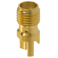


 工商网监
湘ICP备2023018690号
工商网监
湘ICP备2023018690号
