AS3630
8A Supercap Flash Driver
General Description
The AS3630 is an inductive high efficient 4MHz dual DCDC step
up converter with several sources. It supports the charging of a
Supercap, its voltage balancing and a highly efficient DCDC step
up from the Supercap to the LED and from VIN to the LED to
power the flash LED with up to 8A. The AS3630 supports the
pre-charging of the Supercap (to VIN) to reduce the startup time
for the flash without reducing the lifetime of the Supercap.
The system concept supports an immediate torch function
without first charging the Supercap.
The AS3630 includes flash timeout, over- undervoltage,
overtemperature and LED short circuit protection.
The AS3630 is controlled by an I²C interface for adjustment of
the currents and timings, set the end of charge voltage and
measure the Supercap and LED parameters through the internal
ADC. A dedicated TXMASK/TORCH input can be used for a torch
button -or- reducing the battery current if a RF PA is operated
at the same time (TX Masking). A hardware enable pin -ON can
be used as a reset input.
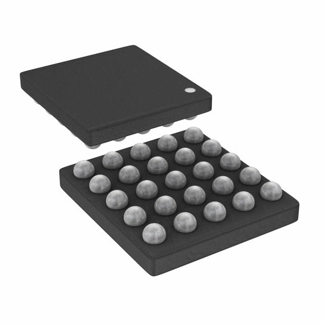
The AS3630 is available in a space-saving WL-CSP 5x5 balls
package measuring only 2.5x2.5x0.6mm and operates over the
-30ºC to +85ºC temperature range.
Figure AS3630 – 1:
Key Benefits and Features
Benefits
Features
Reduce Supercap size
Dual high efficiency boost converter with soft start
allows small coils
Instantaneous Torch operation for improved user
experience
Immediate Torch functions with charging of the
Supercap
Tiny external coils
4MHz fixed frequency DCDC
System Safety
10bit ADC converter for system monitoring with
Protection functions:
Automatic Flash Timeout timer to protect the LED
Overvoltage and undervoltage Protection
LED (NTC) and device Overtemperature Protection
LED short/open circuit protection
Improved thermal performance (ground = heat sink)
Flash LED(s) cathode connected to ground:
8A Supercap Flash Driver
AS3630 – 1
�Benefits
Features
Fine control of current to fit to applications
LED currents (fully adjustable by interface)
• 8A for 33ms and 6A for 120ms (Flash), 2.9mA 272mA for torch
• 1mA-8mA indicator current
Full control and hardware ON pin for easier system
integration
I²C Interface with Interrupt output and ON pin
The device is ideal for Flash/Torch for mobile phones, DSC and
Tablets.
Applications
Figure AS3630 – 2:
Typical Operating Circuit
����������
����
���
����
��
���
�����
���&�.
�,(�
�#��
��3
�����3
�����3
�����456�
��� �!��
)*�+
�%�&'(
�
�
����!$�
!����
���!$�
�������/"����������
�������
������
��������
���
�����������
��
��
�������
��������
�2*��#���!��
�"-"�
�������
��!���
����!$�
���
���
�
�� �
)�0�&1
���
�,(&��
(
�������
�
�����
�
�����
���"�
���
���
��
�$
�
�
17����1
�������
$
�
��
�
!
��
������3
Typical Operating Circuit: Shows the main function blocks of the AS3630.
AS3630 – 2
8A Supercap Flash Driver
�Pin Assignment
Figure AS3630 – 3:
Pin Assignments (Top View)
������
����
��
��
�"�
����
������./�����������
�������
�"�
����������!�
)��+
�%�&'(
�����
����!�
���
���&
,
-(�
���������
�$
��
���� ���
�$
�#������
�������
�����
��+��
$�����
�$
������
�����!�
���
��#
��
����
)�0�&1
������
��
���
��
�������� �������
��
��
���
��
��#
�)
�!��
�2
�������
�����
��
��
�)
��
�2
����
�2
��#
��
�"�
��
�!��
��
���
�)
����
��
�"�
��
�!��
��
�"�
�)
#������
�2
����
��
�"�
��
�!��
��
�"�
�)
#������
�2
��#
#������
������
�������
8A Supercap Flash Driver
���
�!��
�!��
AS3630 – 3
�Pin Description
Figure AS3630 – 4:
Pin Description
Pin Number
Pin Name
Description
A1
STROBE
A2
NTC
LED temperature sensor input - connect to NTC and connect its
GND with a separate ground wire to AGND
A3
SDA2
Digital input, open drain output - serial data input/output for I²C
interface (needs external pullup resistor)
A4
SCL2
Digital Input3 - serial clock input for I²C mode
A5
AGND
B1
VSUPERCAP
B2
IND_OUT
Digital input with pulldown to control strobe time for flash
function1
Analog ground - connect to ground (GND)
Supercap connection
Indicator LED current source output
B3
TXMASK/TORCH
Function 1
• “TXMASK” Connect to RF power amplifier enable signal reduces currents during flash to avoid a system shutdown
due to parallel operation of the RF PA and the flash driver.
Function 2
• “TORCH” Operate torch current level without using the I²C
interface to operate the torch without need to start a
camera processor (if the I²C is connected to the camera
processor.
B4
ON
Digital Input active high - a logic 1 enables of the AS3630; a logic
0 resets the AS3630
B5
VIN
Positive supply voltage input - connect to supply and make a
short connection to input capacitor CVIN and to coil LDCDC1
C1
BAL
Supercap balance pin - balances both single capacitors inside the
Supercap
C2
SW2
DCDC converter 2 switching node - make a short connection to
the coil LDCDC2 and connect all SW2 pins together on top plane
C3
PGND
Power ground - connect to ground (GND) and connect all PGND
pins together on top plane
C4
INT
Open drain interrupt output - active low (needs external pullup
resistor)
C5
VDCDC
DCDC converter 1 and 2 output capacitor - make a short
connection to CVOUT1 and connect all VDCDC pins together as
short as possible
AS3630 – 4
8A Supercap Flash Driver
�Pin Number
Pin Name
Description
D1
VDCDC
DCDC converter 1 and 2 output capacitor - make a short
connection to CVOUT1 and connect all VDCDC pins together as
short as possible
D2
SW2
DCDC converter 2 switching node - make a short connection to
the coil LDCDC2 and connect all SW2 pins together on top plane
D3
PGND
Power ground - connect to ground (GND) and connect all PGND
pins together on top plane
D4
SW1
DCDC converter 1 switching node - make a short connection to
the coil LDCDC1 and connect all SW1 pins together on top plane
D5
LED_OUT
Flash LED current source output and connect all LED_OUT pins
together on top plane
E1
VDCDC
DCDC converter 1 and 2 output capacitor - make a short
connection to CVOUT1 and connect all VDCDC pins together as
short as possible
E2
SW2
DCDC converter 2 switching node - make a short connection to
the coil LDCDC2 and connect all SW2 pins together on top plane
E3
PGND
Power ground - connect to ground (GND) and connect all PGND
pins together on top plane
E4
SW1
DCDC converter 1 switching node - make a short connection to
the coil LDCDC1 and connect all SW1 pins together on top plane
E5
LED_OUT
Flash LED current source output and connect all LED_OUT pins
together on top plane
1. Application Information: The pin STROBE is usually connected directly to the camera processor.
2. When SCL and SDA exchanged, the AS3630 uses a different I²C address and the functionality of SCL/SDA is also exchanged - see “I²C Address
Selection” on page 43.
3. Only input: The AS3630 does not perform clock stretching.
8A Supercap Flash Driver
AS3630 – 5
�Stresses beyond those listed under “Absolute Maximum
Ratings“ may cause permanent damage to the device. These are
stress ratings only. Functional operation of the device at these
or any other conditions beyond those indicated under
“Operating Conditions” is not implied. Exposure to absolute
maximum rating conditions for extended periods may affect
device reliability.
Absolute Maximum Ratings
Figure AS3630 – 5:
Absolute Maximum Ratings
Parameter
Min
Max
Units
VIN, SDA, SCL, ON, STROBE,
TXMASK/TORCH, INT, IND_OUT, NTC
and BAL to GND
-0.3
+7.0
V
SDA, SCL, ON, STROBE,
TXMASK/TORCH, INT, IND_OUT, NTC to
GND
-0.3
VIN + 0.3
V
VDCDC, SW1, SW2, VDCDC, LED_OUT and
VSUPERCAP to GND
-0.3
+11
V
VDCDC to SW1
VDCDC to SW2
VDCDC to LED_OUT
VSUPERCAP to BAL
-0.3
AGND, PGND to GND
0.0
-100
Input Pin Current without causing
latchup
Comments
V
Diode between
• VDCDC and SW1
• VDCDC and SW2
• VDCDC and LED_OUT
• VSUPERCAP and BAL
0.0
V
Connect AGND and PGND to GND
directly below the ball (short
connection required)
+100
+IIN
mA
Norm: EIA/JESD78
Continuous Power Dissipation (TA = +70ºC)
Continuous power dissipation
Continuous power dissipation derating
factor
2770
mW
37
mW/ºC
PT1
PDERATE2
Electrostatic Discharge
ESD HBM
±2000
V
Norm: JEDEC JESD22-A114F
ESD MM
±100
V
Norm: JEDEC JESD 22-A115-B
AS3630 – 6
8A Supercap Flash Driver
�Parameter
Min
Max
Units
Comments
Temperature Ranges and Storage Conditions
Junction Temperature
Storage Temperature Range
Humidity
Body Temperature during Soldering
Moisture Sensitivity Level (MSL)
+150ºC internally limited only
during flash (max. 20000s)
+125
ºC
-55
+125
ºC
5
85
%
Non condensing
+260
ºC
According to IPC/JEDEC J-STD-020
MSL 1
Represents a max. floor life time of
unlimited
1. Depending on actual PCB layout and PCB used.
2. PDERATE derating factor changes the total continuous power dissipation (PT) if the ambient temperature is not 70ºC. Therefore for e.g.
TAMB=85ºC calculate PT at 85ºC = PT - PDERATE * (85ºC - 70ºC)
8A Supercap Flash Driver
AS3630 – 7
�Electrical Characteristics
All limits are guaranteed. The parameters with min and max
values are guaranteed with production tests or SQC (Statistical
Quality Control) methods.
V VIN = +2.5V to +4.8V, TAMB = -30ºC to +85ºC, unless otherwise
specified. Typical values are at V BAT = +3.7V, TAMB = +25ºC,
unless otherwise specified.
Figure AS3630 – 6:
Electrical Characteristics
Symbol
Parameter
Conditions
Min
Typ
Max
Units
2.5
3.7
4.8
V
General Operating Conditions
VVIN
Supply Voltage
ISHUTDOWN
Shutdown
Current
AS3630 off, VBAT20.58mA
10
(3000mA range)
>23.53mA
11
(4000mA range)
Disabled
If the voltage on LED_OUT stays below V LEDSHORT, a shorted LED
is detected.
8A Supercap Flash Driver
AS3630 – 35
�If the voltage on VDCDC reaches V VOUTMAX and the voltage across
the current source between VDCDC and LED_OUT is below
V FLASH_COMP an open LED is detected.
If an open or shorted LED is detected, bit fault_led is set. The
DCDCs and current sinks are disabled and the Supercap is
discharged by setting mode_setting=001b. In external torch
mode, the register txmask_torch_mode is reset.
Note: Short/open LED detection is disabled in PWM operating
mode (mode_setting=101b). The voltage on VDCDC will
nevertheless never exceed V VOUTMAX.
AS3630 DIE Overtemperature Detected - fault_overtemp
The junction temperature of the AS3630 is continuously
monitored. If the temperature exceeds TOVTEMP, the DCDCs are
stopped, the current sources are disabled (instantaneous) and
the bit fault_overtemp is set (but the operating mode
mode_setting is not changed). The driver is automatically
re-enabled once the junction temperature drops below
TOVTEMP-TOVTEMPHYST.
Note: If an overtemperature is detected in Supercap pre-charge,
transition or charge mode, charging is temporarily disabled
until the temperature drops, but the register bit fault_overtemp
is not set.
Timeout Fault - fault_timeout
If the flash is started a timeout timer is started in parallel. If the
flash duration defined by the STROBE input (strobe_on=1 and
strobe_type=1, see Figure 31) exceeds tFLASHTIMEOUT
(adjustable by register flash_timeout), the DCDCs are stopped
and the flash current source (on pin LED_OUT) is disabled
(ramping down) and fault_timeout is set.
If the flash duration is defined by the timeout timer itself
(strobe_on = 0, see Figure 28), the register fault_timeout is not
set after the flash has been finished.
AS3630 will automatically select the operating mode according
to register mode_after_flash shown in Figure 26.
Supercap Short Detected - fault_sc_short
In all operating modes except shutdown (mode_setting not
000b or 001b) once VSUPERCAP is above 2.4V both internal
capacitors of the Supercap (VSUPERCAP-BAL and BAL-GND) are
monitored if they are shorted. If any of them is shorted10,
charging is stopped and the Supercap is discharged by setting
mode_setting=001b andfault_sc_short is set.
10. VSUPERCAP-BAL is compared with typ. 950mV, BAL-GND is compared with typ. 700mV.
AS3630 – 36
8A Supercap Flash Driver
�NTC - Flash LED Overtemperature Protection - fault_ntc
Figure AS3630 – 34:
NTC Internal circuit
���
�������� �
������ �
�
�� �
�������� ��������
��
������
�� ������
�������� �
�
�
��
�
�����
��
�������
�
��
��
��
�
��������
��������
�� �����
���
�
�������
� �!
��"
���� ����� #
The NTC input can be used to monitor the flash LED temperature
if ntc_on=1. A internal current source controlled by NTC_current
sources a current on pin NTC - see Figure 34. If the voltage on
pin NTC drops below VNTC_TH, fault_ntc is set, the DCDCs are
stopped and the flash current source (on pin LED_OUT) is
disabled (instantaneous) by setting mode_setting depending
on register mode_after_flash. If mode_after_flash=001b then
mode_setting=001b (shutdown and discharge Supercap). All
other settings of mode_after_flash result in mode_setting=000b
(shutdown).
As the external NTC cannot measure the LED temperature in
real time during a short high current flash pulse (the duration
from heating up of the LED until the NTC recognizes a too hot
LED is usually too long), it is advisable to measure the LED
temperature before the flash pulse (with the ADC and
NTC_current) and judge how much current can be driven
through the LED (to be estimated depending on LED heat sink
and is usually specified by the LED manufacturer).
LED Current Reduction Triggered - fault_current_reduced
If during flash the LED current has been reduced (for conditions
when this can occur see DCDC1 / DCDC2 Operating Principle
During Flash operating mode 3.), the register bit
fault_current_reduced is set for indication and lled_current_min
is set to the reduced LED current.
The operating mode is not changed and the DCDCs and current
source continue operation.
8A Supercap Flash Driver
AS3630 – 37
�Supply Undervoltage Protection
If the voltage on the pin VIN (=battery voltage) is or falls below
V UVLO, the AS3630 is kept in shutdown state and all registers are
set to their default state.
Interrupt Output
INT is an open drain, active low output. The internal circuit to
control this pin is shown in Figure 35.
Figure AS3630 – 35:
Interrupts Processing
���������
���
$��� #��������
#� �
����
���� �������
���
!��"���� ����
������������
�
����
����
�� �
��
��
������!"�
#"
��
����
�� ����
�
� �
� ��
�
�������
����
��
������������
��
����
� �����������
�
Once an interrupt event occurs (e.g. end of charge of Supercap;
detailed description of interrupt events in “AS3630 Torch
Operation with Duration Synchronized to STROBE Input ” on
page 35, the interrupt flip flop is set (register status_eoc=1). If
the interrupt mask is high (register status_eoc_mask=1), the
output INT is pulled to low signalizing an interrupt condition.
All 8 interrupt flip flops are automatically cleared upon readout
of register Fault / Status.
ADC
The ADC is programmed by setting the ADC channel in register
ADC_channel (page 52) and the ADC conversion is performed
after setting ADC_convert (page 52).
The actual timing when the ADC conversion is started / finished
is programmed with ADC_convert as shown in Figure 36:
AS3630 – 38
8A Supercap Flash Driver
�Figure AS3630 – 36:
ADC Timings
�����������
���� !�
"#����������$$
%���
&'�
�����������
��� �!�
"������������� ���'�
���
����
�
�����������
�����������
���
"���
�%����� ���'�
!�
�
����������
��
��������
�����
��������� �!
��������� �!
��������� �!
�
������
� ������ �
()$�
���������
���
�
Once the conversion is finished ADC_convert returns to 00b,
status_adc_eoc is set, and the result data is available from
register 4 * ADC_D9-D2 + ADC_D1-D0.
Note: The ADC input ranges and gains are described in Figure 6
subsection ADC.
I²C Mode Serial Data Bus
The AS3630 supports the I²C bus protocol. A device that sends
data onto the bus is defined as a transmitter and a device
receiving data as a receiver. The device that controls the
message is called a master. The devices that are controlled by
the master are referred to as slaves. A master device that
generates the serial clock (SCL), controls the bus access, and
generates the START and STOP conditions must control the bus.
The AS3630 operates as a slave on the I²C bus. Within the bus
specifications a standard mode (100kHz maximum clock rate)
and a fast mode (400kHz maximum clock rate) are defined. The
AS3630 works in both modes. Connections to the bus are made
through the open-drain I/O lines SDA and SCL.
The following bus protocol has been defined (Figure 37):
• Data transfer may be initiated only when the bus is not
busy.
• During data transfer, the data line must remain stable
whenever the clock line is HIGH. Changes in the data line
while the clock line is HIGH are interpreted as control
signals.
Accordingly, the following bus conditions have been defined:
Bus Not Busy
Both data and clock lines remain HIGH.
8A Supercap Flash Driver
AS3630 – 39
�Start Data Transfer
A change in the state of the data line, from HIGH to LOW, while
the clock is HIGH, defines a START condition.
Stop Data Transfer
A change in the state of the data line, from LOW to HIGH, while
the clock line is HIGH, defines the STOP condition.
Data Valid
The state of the data line represents valid data when, after a
START condition, the data line is stable for the duration of the
HIGH period of the clock signal. The data on the line must be
changed during the LOW period of the clock signal. There is one
clock pulse per bit of data.
Each data transfer is initiated with a START condition and
terminated with a STOP condition. The number of data bytes
transferred between START and STOP conditions are not
limited, and are determined by the master device. The
information is transferred byte-wise and each receiver
acknowledges with a ninth bit.
Acknowledge
Each receiving device, when addressed, is obliged to generate
an acknowledge after the reception of each byte. The master
device must generate an extra clock pulse that is associated
with this acknowledge bit.
A device that acknowledges must pull down the SDA line during
the acknowledge clock pulse in such a way that the SDA line is
stable LOW during the HIGH period of the acknowledge-related
clock pulse. Of course, setup and hold times must be taken into
account. A master must signal an end of data to the slave by not
generating an acknowledge bit on the last byte that has been
clocked out of the slave. In this case, the slave must leave the
data line HIGH to enable the master to generate the STOP
condition.
AS3630 – 40
8A Supercap Flash Driver
�Figure AS3630 – 37:
Data Transfer on I²C Serial Bus
SDA
MSB
7 bit SLAVE
ADDRESS
R/W
DIRECTION
ACKNOWLEDGEMENT SIGNAL FROM
RECEIVER
ACKNOWLEDGEMENT SIGNAL FROM
RECEIVER
SCLK
1
2
6
7
8
9
1
2
3-7
8
9
ACK
START
CONDITION
REPEATED IF
MORE BYTES
ARE TRANS-
STOP CONDITION
OR REPEATED
START CONDI-
Depending upon the state of the R/W bit, two types of data
transfer are possible:
1. Data transfer from a master transmitter to a slave
receiver. The first byte transmitted by the master is the
slave address. Next follows a number of data bytes. The
slave returns an acknowledge bit after each received
byte. Data is transferred with the most significant bit
(MSB) first.
2. Data transfer from a slave transmitter to a master
receiver. The master transmits the first byte (the slave
address). The slave then returns an acknowledge bit,
followed by the slave transmitting a number of data
bytes. The master returns an acknowledge bit after all
received bytes other than the last byte. At the end of the
last received byte, a “not acknowledge” is returned. The
master device generates all of the serial clock pulses and
the START and STOP conditions. A transfer is ended with
a STOP condition or with a repeated START condition.
Since a repeated START condition is also the beginning
of the next serial transfer, the bus is not released. Data
is transferred with the most significant bit (MSB) first.
The AS3630 can operate in the following two modes:
1. Slave Receiver Mode (Write Mode): Serial data and
clock are received through SDA and SCLK. After each
byte is received an acknowledge bit is transmitted.
START and STOP conditions are recognized as the
beginning and end of a serial transfer. Address
recognition is performed by hardware after reception of
the slave address and direction bit (see Figure 38). The
slave address byte is the first byte received after the
master generates the START condition. The slave
address byte contains the 7-bit AS3630 address, which
is shown in Figure 42, followed by the direction bit
(R/W), which, for a write, is 0. 11 After receiving and
decoding the slave address byte the device outputs an
acknowledge on the SDA line. After the AS3630
8A Supercap Flash Driver
AS3630 – 41
�acknowledges the slave address + write bit, the master
transmits a register address to the AS3630. This sets the
register pointer on the AS3630. The master may then
transmit zero or more bytes of data, with the AS3630
acknowledging each byte received. The address pointer
will increment after each data byte is transferred. The
master generates a STOP condition to terminate the
data write.
2. Slave Transmitter Mode (Read Mode): The first byte is
received and handled as in the slave receiver mode.
However, in this mode, the direction bit indicates that
the transfer direction is reversed. Serial data is
transmitted on SDA by the AS3630 while the serial clock
is input on SCLK. START and STOP conditions are
recognized as the beginning and end of a serial transfer
(Figure 39 and Figure 40). The slave address byte is the
first byte received after the master generates a START
condition. The slave address byte contains the 7-bit
AS3630 address, which is shown in Figure 42, followed
by the direction bit (R/W), which, for a read, is 1.12 After
receiving and decoding the slave address byte the
device outputs an acknowledge on the SDA line. The
AS3630 then begins to transmit data starting with the
register address pointed to by the register pointer. If the
register pointer is not written to before the initiation of
a read mode the first address that is read is the last one
stored in the register pointer. The AS3630 must receive
a “not acknowledge” to end a read.
S
Figure 42
Figure AS3630 – 38:
Data Write - Slave Receiver Mode
0
A
XXXXXXXX
XXXXXXXX
A
S - Start
A - Acknowledge (ACK)
P - Stop
A
XXXXXXXX
A
XXXXXXXX
A
P
Data Transferred
(X + 1 Bytes + Acknowledge)
11. The address for writing to the AS3630 is shown in Figure 42
12. The address for read mode from the AS3630 is shown in Figure 42
AS3630 – 42
8A Supercap Flash Driver
�
S
Figure AS3630 – 39:
Data Read (from Current Pointer Location) - Slave Transmitter Mode
Figure 42
1
A
XXXXXXXX
A
XXXXXXXX
A
S - Start
A - Acknowledge (ACK)
P - Stop
NA - Not Acknowledge (NACK)
XXXXXXXX
A
XXXXXXXX
NA
P
Data Transferred
(X + 1 Bytes + Acknowledge)
Note: Last data byte is followed by a NACK
S
Figure 42
0
A
XXXXXXXX
A
XXXXXXXX
S - Start
Sr - Repeated Start
A - Acknowledge (ACK)
P - Stop
NA - Not Acknowledge (NACK)
A
Sr
Figure 42
A
XXXXXXXX
1
A
XXXXXXXX
Figure AS3630 – 40:
Data Read (Write Pointer, Then Read) - Slave Receive and Transmit
A
XXXXXXXX
NA
P
Data Transferred
(X + 1 Bytes + Acknowledge)
Note: Last data byte is followed by a NACK
I²C Address Selection
Note: It is required to read the register Fixed ID twice after
startup in order for the I²C address selection to identify the I²C
address used.
The AS3630 features two I²C slave addresses without having a
dedicated address selection pin. The selection of the I²C address
is done with the interconnection of AS3630 to the bus lines
shown in the figure below. The serial interface logic inside
AS3630 is able to distinguish between a direct I²C connection
to the master or a second option where data and clock line are
crossed. Therefore it is possible to address a maximum of two
AS3630 slaves on one I²C bus.
8A Supercap Flash Driver
AS3630 – 43
�Figure AS3630 – 41:
I²C Address Selection Application Diagram
���
���
��
���
���
��
����
����
������
���
��������
��
�������
���� ������
����
����
������
���
��������
���
���
��
The I²C address use is defined according to the figure below:
Figure AS3630 – 42:
I²C Addresses for AS3630
7 bit I²C
address
8 bit I²C read
address
8 bit I²C write
address
1
(default; SCLK and SDA directly connected)
30h
60h
61h
2
(SCLK and SDA exchanged)
31h
62h
63h
Device Number
Figure 41 on page 44
8A Supercap Flash Driver
AS3630 – 44
�Register Description
Figure AS3630 – 43:
Register Overview
Addr
00h
Name
Fixed ID
fixed_id
Access
RO
Reset Value
17h - fixed id (e.g. to check I²C communication)
Note: It is required to read the register Fixed ID twice after startup in order for the I²C address selection to identify the I²C address used.
Version
reserved
version
Access
RO
RO
Reset Value
NA
X
Don't use by application
Don't use by application
01h
8A Supercap Flash Driver
AS3630 – 45
�Addr
Name
Current Set LED
led_current
Access
RW
Reset Value
15h (206mA)
LED Current pin LED_OUT; the range of this setting is defined by led_current_range
LSB is 9.8mA (2500mA/255) for led_current_range=00b
LSB is 980μA (250mA/255) for led_current_range=01b
LSB is 11.76mA (3000mA/255) for led_current_range=10b
led_current_range
02h
AS3630 – 46
led_current
00b
01b
10b
11b
00h
0mA
0mA
0mA
0mA
01h
9.8mA
02h
19.6mA
03h
29.4mA
Don’t use below 10mA (code
0Bh)
Don’t use
below
2506mA
(code D5h)
Don’t use
below
2996mA
(code BFh)
...
...
D5h
2088mA
209mA
2506mA
3341mA
...
...
...
...
...
FFh
2500mA
250mA
3000mA
4000mA
8A Supercap Flash Driver
�Addr
Name
Boost/TXMask
Current
led_current_range
curr_limit_curr_r
ed
coil1_txmask_curr_red
txmask_torch_mode
Access
RW
RW
RW
RW
Reset Value
00b
0b
011b
00b
Reduce LDCDC1 current in steps of coil1_peak
currents during TXMask
(this is a delta value; e.g. -1 means one current
step reduction e.g. from 2.5A to 2.0A; -4
means four steps e.g. from 2.5A to 750mA. if
the reduction would result in a negative value,
DCDC1 is switch off during TXMask event)
000 … -1
001 … -2
010 … -3
011 … -4 - default value
100 … -5
101 … -6
Function of TXMASK/TORCH
pin
00 … no effect (default)
01 … txmask operation
mode (applies for flash
mode, mode_setting=111b)
10 … external torch mode
(applies for shutdown mode,
mode_setting=000b or
001b, max. led_current ≤
460mA)
11 … don't use
03h
Comment
Range setting for led_current
00...10-2500mA range
01...10-250mA range
10...2500-3000mA range
11...don’t use
use range “10” only for currents
above 2500mA
110 … -7
111 … -8
If set, reduce LED current if LDCDC1 and LDCDC2 currents are hit and current source ILED cannot drive
the output current.
Note: In flash mode LDCDC1 is usually operated in current limit.
8A Supercap Flash Driver
AS3630 – 47
�Addr
Name
Coil and Charge
Current
charge_current
coil2_peak
coil1_peak
Access
RW
RW
RW
Reset Value
01b
010b
100b
Defines charging current of
Supercap for pre-charge and
‘transition’ (to charge);
afterwards coil1_peak defines
current
04h
Comment
00 … 200mA - low quiescent
current mode
01 … 500mA
10 ... 750mA
11 … 1000mA
AS3630 – 48
LDCDC2 Coil Peak current limit
000 … don’t use
001 … don’t use
010 … 2.43A (default)
011 … 3.14A
100 … 3.86A
101 … 4.57A
110 … 5.29 A
111 … 6.0A
LDCDC1 Coil Peak current limit
000 … don’t use
001 … 750mA
010 … 1A
011 … 1.5A
100 … 2A (default)
101 … 2.5A
110 … 3A
111 … 3.5A
8A Supercap Flash Driver
�Addr
Name
Charge / Low
Voltage
bal_force_on
end_of_charge_voltage
vin_low_v
Access
RW
RW
RW
Reset Value
0b
5h
5h
Define Supercap end of charge
Note: In pre-charge the Supercap is always charged close to VVIN;
therefore end_of_charge_voltage ≥ VVIN
05h
0h … 4.61V
1h … 4.7V
2h … 4.79V
3h … 4.88V
4h … 4.97V
5h … 5.06V (default)
6h … 5.15V
7h … 5.24V
8h … 5.33V
9h … 5.42V
Ah … 5.51V
Bh … 5.61V
Ch … 5.7V
Dh … 5.79V
Eh … 5.88V
Fh … 5.97V
Reduce coil1_peak current if the VIN voltage
falls below vin_low_v 0h function is disabled
1h 3.0V
2h 3.07V
3h 3.14V
4h 3.22V
5h 3.3V - default
6h 3.38V
7h 3.47V
0 … balancing circuit is enabled according to the operating mode
1 … balancing circuit is always enabled
8A Supercap Flash Driver
AS3630 – 49
�Addr
Name
Flash Timer
Access
Reset Value
ind_rampup_s
mooth
ind_rampdo
wn_smooth
flash_timeout
RW
RW
RW
1
1
0Fh
Flash timeout timer - define maximum flash time
4ms steps from 0…15h; 16ms steps from 16h to 63h
06h
Smooth
rampup during
indicator
blinking if
ind_on=1
0... none
1...smooth
(380ms)
AS3630 – 50
Smooth
rampdown
during
indicator
blinking if
ind_on=1
0... none
1...smooth
(380ms)
00h … 4ms
01h … 8ms
02h … 12ms
03h … 16ms
04h … 20ms
05h … 24ms
06h … 28ms
07h … 32ms
08h … 36ms
09h … 40ms
0Ah … 44ms
0Bh … 48ms
0Ch … 52ms
0Dh … 56ms
0Eh … 60ms
0Fh … 64ms
10h … 68ms
11h … 72ms
12h … 76ms
13h … 80ms
14h … 84ms
15h … 88ms
16h … 104ms
17h … 120ms
18h … 136ms
19h … 152ms
1Ah … 168ms
1Bh … 184ms
1Ch … 200ms
1Dh … 216ms
1Eh … 232ms
1Fh … 248ms
20h … 264ms
21h … 280ms
22h … 296ms
23h … 312ms
24h … 328ms
25h … 344ms
26h … 360ms
27h … 376ms
28h … 392ms
29h … 408ms
2Ah … 424ms
2Bh … 440ms
2Ch … 456ms
2Dh … 472ms
2Eh … 488ms
2Fh … 504ms
30h … 520ms
31h … 536ms
32h … 552ms
33h … 568ms
34h … 584ms
35h … 600ms
36h … 616ms
37h … 632ms
38h … 648ms
39h … 664ms
3Ah … 680ms
3Bh … 696ms
3Ch … 712ms
3Dh … 728ms
3Eh … 744ms
3Fh … 760ms
8A Supercap Flash Driver
�Addr
Name
Control
ind_on
mode_after_flash
keep_sc_ch
arged
ntc_on
mode_setting
Access
RW
RW
RW
RW
RW
Reset Value
0b
11b
0b
0b
001b
Hardware
NTC
protection
of LED_OUT
0…off
1…on
000 ... shutdown or external torch mode (leave
Supercap charged)
001 ... shutdown or external torch mode and
discharge Supercap with RDIS_CHARGE - default
010 ... pre charge Supercap (to VIN)
011 ... charge Supercap
100 ... torch operation (wo/ Supercap) - max.
led_current ≤ 460mA
101 ... PWM Operation (main LED); max.
led_current ≤ 303.9mA; led_current_range is
set to 00b
110 ... torch operation sync to STROBE
(STROBE=1: LED on; STROBE=0: LED off ) max.
led_current ≤ 931mA
111 ... Flash Operation
07h
8A Supercap Flash Driver
Iindicator
current source
on IND_OUT
0 … off
1… on, (current
set by
ind_current)
Set the operating mode after
flash (see Figure 23 on page 27):
00... shutdown (leave Supercap
charged)
01... shutdown and discharge
Supercap
10... pre charge Supercap (to VIN)
11... charge Supercap
If set during
PWM,Torch
or Charge
operation
keep
Supercap
charged
with 10mA
current
AS3630 – 51
�Addr
Name
strobe_on
strobe_type
ADC_convert
ADC_channel
Access
RW
RW
RW
RW
Reset Value
1b
1b
00b
0h
Strobe and ADC
control
08h
Enable STROBE
input
STROBE
input is
0 … edge
sensitive
1 … level
sensitive
Control ADC conversion register is automatically reset to
00 after the conversion is
finished
Select ADC channel for conversion
0h … VDCDC
1h … LED_OUT
2h ... Tjunc (DIE Junction temperature)
3h … VSUPERCAP
4h ... don’t use
5h ... BAL
6h … VIN
7h ... NTC
8h … IND_OUT
9h ... don’t use
Ah ... PGND.
Bh ... don’t use
Ch ... STROBE
Dh ... INT
Eh ... ON
Fh ... don’t use
00 … ADC shutdown (no conversion performed or end of conversion)
01 … start ADC conversion immediately
10 … do ADC conversion 1.5ms after current rampup (beginning of flash)
11 … do ADC conversion just before current rampdown (at end of flash; flash duration is extended
by 100μs)
AS3630 – 52
8A Supercap Flash Driver
�Addr
Name
Fault / Status
Access
Reset Value
status_eoc
status_adc_e
oc
fault_led
fault_overte
mp
fault_timeo
ut
fault_sc_short
fault_ntc
fault_current
_reduced
SS_RC1
SS_RC
SS_RC
SS_RC
SS_RC
SS_RC
SS_RC
SS_RC
0b
0b
0b
0b
0b
0b
0b
0b
Shorted or open
LED (LED_OUT)
detected (see
page 35)
Overtemper
ature
(Tjunction)
triggered
(see
page 36)
Timeout has
triggered
(see
page 36)
Detect a
shorted
Supercap
(BAL-GND) or
(VSUPERCAPBAL) during
charging (see
page 36)
LED
Overtemper
ture
detection
hit
(monitored
by NTC) (see
page 36)
LED Current
has been
reduced and
register
09h
End Of
Supercap
Charge (see
page 35)
ADC end of
conversion
reached (see
page 35)
led_current_min reports min. led current during flash cycle (see page 37)
status_eoc_mas
k
status_adc_e
oc_mask
fault_led_mask
fault_overte
mp_mask
fault_timeo
ut_mask
fault_sc_short
_mask
fault_ntc_m
ask
fault_current
_reduced_m
ask
Access
RW
RW
RW
RW
RW
RW
RW
RW
Reset Value
0b
0b
0b
0b
0b
0b
0b
0b
If set,
overtemper
ature
(Tjunction)
triggers INT
If set
timeout
triggers INT
If set
fault_sc_short
triggers INT
If set
fault_ntc
triggers INT
If set
fault_current
_reduced
triggers INT
Interrupt Mask
0Ah
If set, end of
Supercap
charge triggers
INT
8A Supercap Flash Driver
If set ADC
end of
conversion
triggers INT
If set, a shorted
or open LED
(LED_OUT)
triggers INT
AS3630 – 53
�Addr
Name
PWM and
Indicator
ind_blink_delay
ind_current
led_out_pwm
Access
RW
RW
RW
Reset Value
01b
000b
000b
Control indicator blinking
function delay between blinks if
ind_on=1
0Bh
00 ... continuously on (no
blinking)
01 ... 512ms
10 ... 1024ms
11 ... 2048ms
Minimum LED
Current
0Ch
IND_OUT current setting if ind_on=1
000 … 1mA
001 … 2mA
010 … 3mA
011 … 4mA
100 … 5mA
101 … 6mA
110 … 7mA
111 … 8mA
PWM modulate LED_OUT current if
mode_setting=PWM operation; automatically
uses led_current_range=00 (10mA...2500mA)
but limits current to 303.9mA (codes 00h...1Fh
for led_current)
000 1/32 PWM at 15.625kHz- subharmonic
oscillation are possible - not recommended to
use
001 don’t use - use 1/16 instead
010 3/32 PWM at 15.625kHz
011 don’t use - use 2/16 instead
100 1/16 PWM at 31.25kHz
101 2/16 PWM at 31.25kHz
110 3/16 PWM at 31.25kHz
111 4/16 PWM at 31.25kHz
led_current_min
Access
RO
Reset Value
00h
At the beginning of a flash pulse, led_current_min is set to led_current then it is reduced upon following condition: (coil1_peak hit
and coil2_peak hit and curr_limit_curr_red=1); led_current_min has the same coding used as led_current (the current reduction
happens in steps as the coding of led_current is done)
AS3630 – 54
8A Supercap Flash Driver
�Addr
Name
ADC MSB
ADC_D9-D2
Access
RO
Reset Value
NA
0Dh
ADC MSB results bit 9 to bit 2
ADC LSB
led_current_rampdown
ADC_D1-D0
Access
RW
RO
Reset Value
00
NA
Automatically ramp-down of
LED current register led_current
during flash
00 ... no ramp-down
01 ...1LSB every 100μs
10 ...1LSB every 200μs
11 ...1LSB every 500μs
ADC LSB results bit 1 to bit 0
0Eh
8A Supercap Flash Driver
AS3630 – 55
�Addr
Name
NTC
test6
skip_enable
ind_blink_on_time
NTC_current
Access
R/W
RW
RW
RW
0
1
10
8h
Reset Value
0Fh
Test bit - don’t
use
Allow
pulse-skip
operation or
force 4MHz
operation
0...4MHz
operation
1...pulse-skip
Control indicator blinking
on-time if ind_on=1 (excluding
rampup/down)
00 ... 0ms (immediate
ramp-down after ramp-up)
01 ... 128ms
10 ... 256ms - default
11 ... 512ms
Current through the NTC when overtemperature protection of
the LEDs (LED_OUT) is monitored
0h … off; use for an external drive of NTC
1h … 40μA
2h … 80μA
3h … 120μA
4h … 160μA
5h … 200μA
6h … 240μA
7h … 280μA
8h … 320μA - default
9h … 360μA
Ah … 400μA
Bh … 440μA
Ch … 480μA
Dh … 520μA
Eh … 560μA
Fh … 600μA
OTP1
OTP_data1
Access
RO
Reset Value
NA
10h
Data of OTP
AS3630 – 56
8A Supercap Flash Driver
�Addr
Name
OTP2
OTP_data2
Access
RO
Reset Value
NA
11h
Data of OTP
OTP3
OTP_data3
Access
RO
Reset Value
NA
12h
Data of OTP
13h
OTP4
OTP_lock
OTP_data4
Access
RO
RO
Reset Value
NA
NA
Data of OTP
0 ... OTP is program-able (unlocked)
1... OTP is locked and no further programming of OTP is possible
1. SS_RC = automatically cleared upon readout
8A Supercap Flash Driver
AS3630 – 57
�Register Map
Figure AS3630 – 44:
Register Map
Addr
Name
Default
00h
Fixed ID
17h
01h
Version
XXh
02h
Current Set
LED
15h
03h
Boost/TXMas
k Current
0Ch
led_current_range
04h
Coil and
Charge
Current
54h
charge_current
05h
Charge / Low
Voltage
2Dh
bal_force_on
06h
Flash Timer
CFh
ind_rampup_s
mooth
07h
Control
61h
ind_on
08h
Strobe and
ADC control
C0h
strobe_on
strobe_type
09h
Fault /
Status1
00h
status_eoc
status_adc_
eoc
AS3630 – 58
fixed_id
reserved
version
led_current
curr_limit_curr
_red
coil1_txmask_curr_red
txmask_torch_mode
coil2_peak
coil1_peak
end_of_charge_voltage
ind_rampdo
wn_smooth
vin_low_v
flash_timeout
mode_after_flash
keep_sc_ch
arged
ntc_on
ADC_convert
fault_led
fault_overt
emp
mode_setting
ADC_channel
fault_timeo
ut
fault_sc_shor
t
fault_ntc
fault_curren
t_reduced
8A Supercap Flash Driver
�Addr
Name
Default
0Ah
Interrupt
Mask
00h
status_eoc_m
ask
status_adc_
eoc_mask
fault_led_mask
fault_overt
emp_mask
fault_timeo
ut_mask
fault_sc_shor
t_mask
fault_ntc_
mask
fault_curren
t_reduced_
mask
0Bh
PWM and
Indicator
40h
0Ch
Minimum
LED Current
NA
led_current_min
0Dh
ADC MSB
NA
ADC_D9-D2
0Eh
ADC LSB
0Xh
0Fh
NTC
68h
10h
OTP1
NA
OTP_data12
11h
OTP2
NA
OTP_data2
12h
OTP3
NA
OTP_data3
13h
OTP4
NA
ind_blink_delay
led_current_rampdown
test6
skip_enable
OTP_lock
Read-Only Register
R/W Register
ind_current
0
led_out_pwm
0
0
ind_blink_on_time
0
ADC_D1-D0
NTC_current
OTP_data4
if writing to read-only register is required, write ‘0’ to read-only positions
(e.g. ADC LSB)
1. The register Fault / Status is a read only register, which is automatically cleared after readout. Therefore only a single I²C access is required to poll the status of the AS3630.
2. If OTP data are fused in-circuit, expect a small yield loss.
8A Supercap Flash Driver
AS3630 – 59
�Application Information
External Components
Supercap
The Supercap performance is critical for the performance of
AS3630. As the Supercap is affected by aging, the flash
performance has to be checked at end of life conditions.
Figure AS3630 – 45:
Recommended Supercap’s
Part
Number
C
ESR
Rated
Voltage
Peak
Rated1
Voltage
Match
ing2
Temp
Range3
Size
DME2Z5R5K43
4M3BT
430mF
±20%
50mΩ
5.5V
4.2V
3μF@4.5V
X5R
6V3
0603
Manufacturer
Murata
www.murata.com
Taiyo Yuden
www.t-yuden.com
If a different input capacitor is chosen, ensure similar ESR value
and at least 3μF capacitance at the maximum input supply
voltage. Larger capacitor values (C) may be used without
limitations.
Optionally add a smaller capacitor in parallel to the input pin
VIN (e.g. Murata GRM155R61C104, >50nF @ 3V, 0402 size).
8A Supercap Flash Driver
AS3630 – 61
�Output Capacitor C DCDC1 , C DCDC2
Low ESR capacitors should be used to minimize VDCDC ripple
and therefore current ripple on the LED. Multi-layer ceramic
capacitors are recommended since they have extremely low
ESR and are available in small footprints. The capacitor should
be located as close to the device as is practical.
X5R dielectric material is recommended due to their ability to
maintain capacitance over wide voltage and temperature
range.
Figure AS3630 – 48:
Recommended DCDCs Capacitor
Part Number
GRM219R61A106ME47
GRM219R61A106ME441
2 x C2012X5R1A106M2
C
TC Code
Related
Voltage
Size
X5R
10V
0805
(2.0x1.25x0.85mm
max 1mm height)
10V
2x0805
(2.0x1.25x0.85mm
max 0.95mm
height)
10μF ±20%
>4.8μF@5V
10μF ±10%
>4.05μF@5V
10μF ±20%
X5R
Manufacturer
Murata
www.murata.com
TDK
www.tdk.com
1. If TAMB4.2μF capacitance at 5V.
If a different output capacitor is chosen, ensure similar ESR
values and at least 4.2μF capacitance at 5V output voltage and
for CDCDC1 10V voltage rating, C DCDC2 6.3V voltage rating.
Inductor L DCDC1
LDCDC1 is used for charging of the Supercap, operate the LED in
torch and PWM operation and in parallel to L DCDC2 to power the
LED during flash. Due to the different durations of the operation
modes, different peak current limits apply (see Figure 49).
The fast switching frequency (4MHz) of the AS3649 allows for
the use of small SMDs for the external inductor. The saturation
current ISATURATION should be chosen to be above the
maximum value of ILDCCD1 13. The inductor should have very
low DC resistance (DCR) to reduce the I2R power losses - high
DCR values will reduce efficiency.
13. Can be adjusted in I²C mode with register coil1_peak
AS3630 – 62
8A Supercap Flash Driver
�Figure AS3630 – 49:
Recommended Inductor
Part Number
L
max. coil1_peak
setting for
DCR
Other modes
Size
Flash
3.2x2.5x0.9mm
max 1.0mm
height
LQM32PN1R0MG0
1.0μH
>0.6μH @
3.0A
60mΩ
2.0A
3.0A
SPM3012T-1R0M
1.0μH
±20%
57mΩ
±10%
2.5A
3.0A
(3.5A2)
3.2x3x1.2
mm
height is max
CIG32W1R0MNE
1.0μH
>0.7μH @
2.7A
>0.6μH @
3.0A
60mΩ
±25%
2.0A
3.0A
3.2x2.5mm
max 1.0mm
height
CKP3225N1R0M
1.0μH
>0.6μH @
3.0A
0.6μH@
2.75A
Manufacturer
1
Murata
www.murata.com
TDK
www.tdk.com
Samsung
Electro-Mechancs
www.sem.samsun
g.co.kr
Taiyo Yuden
www.t-yuden.com
45mΩ
2.5A
2.5A
2.5x2.0x1.2mm
height is max
1. Flash pattern: 200ms/3A, 200ms pause, 200ms/3A, 2s then repeat again (no limit on the number of total cycles)
Alternative pattern with 1000ms/1.6A, 200ms pause, 200ms/3A, 200ms pause, 200ms/3A, 2s then repeat again. (no limit on the number of
total cycles)
2. Check with coil supplier
3. Check with coil supplier for worst case flash pattern.
If a different inductor is chosen, ensure similar DCR values and
at least0.6μH inductance at ILDCCD1 set by coil1_peak.
Inductor L DCDC2
LDCDC2 is used in parallel to L DCDC1 to power the LED during
flash. The whole current from the Supercap flows through
LDCDC2 therefore a high power inductor is required.
The fast switching frequency (4MHz) of the AS3649 allows for
the use of small SMDs for the external inductor. The saturation
current ISATURATION should be chosen to be above the
maximum value of ILDCCD2 14. The inductor should have very
low DC resistance (DCR) to reduce the I2R power losses - high
DCR values will reduce efficiency
14. Can be adjusted in I²C mode with register coil2_peak
8A Supercap Flash Driver
AS3630 – 63
�Figure AS3630 – 50:
Recommended Inductor
Part Number
L
MPI4040R2-1R0-R
1.0μH
>0.6μH @ 6.0A
DCR
25mΩ
max.
coil2_peak
setting
Size
6.0A
(max. value)
4.06x4.45x1
.5mm
height is
max
1
MPI4040R1-1R0-R
1.0μH
>0.6μH @ 6.0A
40mΩ
check with
coiltronics
4.06x4.45x1
.2mm
height is
max
XAL4020-102ME_
1.0μH
>0.6μH @ 6.0A
13.25mΩ
6.0A
(max. value)
4x4x2mm
max 2.1mm
height
XFL4020-102ME_
SPM4012T-1R0M
1.0μH
>0.6μH @
5.29A
1.0μH ± 20%
14.4mΩ
38mΩ
57mΩ
±10%
5.29A
4x4x2mm
max 2.1mm
height
4.57A
4.4x4.1x1.2
mm
height is
max
3.0A
(3.5A2)
3.2x3x1.2
mm
height is
max
SPM3012T-1R0M
1.0μH ± 20%
LQM32PN1R0MG0
1.0μH
>0.6μH @ 3.0A
60mΩ
3.0A3
3.2x2.5x0.9
mm
max 1.0mm
height
CIG32W1R0MNE
1.0μH
>0.7μH @ 2.7A
>0.6μH @ 3.0A
60mΩ
±25%
3.0A
3.2x2.5mm
max 1.0mm
height
CKP3225N1R0M
1.0μH
>0.6μH @ 3.0A


 工商网监
湘ICP备2023018690号
工商网监
湘ICP备2023018690号
