JYH HSU(JEC)ELECTRONICS LTD.,
Approved/Recognized Type
Related Standard
Certificate NO
CQC (China)
IEC 60384-14
CQC13001103539
KC (Korea)
K60384
SU03044-9002
UL(usa)
CSA(Canada)
ENEC (EU)
IEC UL 60384
E356696
EN 60384-14
ENEC-00984
VDE (Germany)
EN 60384-14
40038643
IEC CB
IEC 60384-14
US-33636-UL
APProved Monogram
Specifications
Operating Temp.Range
-40℃
to
Use temperature range
-40℃
to +125℃
Applicable Standards
UL, CSA, CQC, ENEC, VDE,KC
Dielectric Withstanding
Voltage
Dissipation Factor
(D.F)
Capacitance(C)
X1
Y2
400VAC
300VAC
Rted Voltage
Test Voltage
300VAC
1800V-2600 VAC for 1 min.
Y5P,Y5U
TANδ(DF) ≦2.5%,measured at 1KHz±10%,1.0 - 5.0 Vrms,25℃
Y5V
TANδ(DF) ≦5.0%,measured at 1KHz±10%,1.0 - 5.0 Vrms,25℃
Range
10 pF
Tolerance
±10%
to
10000 pF. measured at 1KHz±10%, 1.0 - 5.0 Vrms, 25℃
Y5P
±10%
InsulationResiatance(IR)
Temperature
Characteristics
+85℃
±20%
Y5U
±20%
Y5V
10000 MΩ
,
1 min , 500 VDC
Type Code
Temp. Coeff.
Temp. Range
Y5P
±10%
-40℃ to +85℃, -40℃ to +125℃
Y5V
+30%~-89%
-40℃ to +85℃, -40℃ to +125℃
Y5U
+22%~-65%
-40℃ to +85℃, -40℃ to +125℃
1
�JYH HSU(JEC)ELECTRONICS LTD.,
Part Number Configuration:
JY 102 K
(1) (2)
2F
(3) (4)
Y5P
(5)
S
T
(6) (编带)
7.5
L
(7)
(8)
(1) AC capacitors,afety
(5) Type code : (B)Y5P, (F)Y5V, (E)Y5U
(2) Rated capacitance
(6) Lead shape:S(直角), I(内弯), O(外弯), X(前后弯)
(3) Tolerance on rated capacitance (7) Pin pitch : 7.5or9.5or10.0
(4) Rated Voltage
(8) Lead length: 3-30mm
Dimensions and Tolerance
B=3.0mm max for AA
L=3-27mm
承认规格详细参数 (Approved Spec. Data)
品名规格
D(MAX)
F±0.8 L(MIN)mm T±0.5mm d±0.05mm
2
DF 值
Amm
B
备注
�JYH HSU(JEC)ELECTRONICS LTD.,
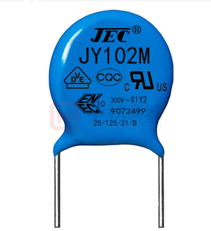
Marking:
a. Trademark or Company name
b. Product Type
JEC
JY Series
c. Nominal Capacitance
222=2200pF,
d. Tolerance
K= ±10%, M= ±20%
e. Recognized Type
cUL, CQC, VDE, ENEC, KC
f. Rated Voltage
X1=400Vac , Y2=300Vac
JEC
JY 222M
1. Packing Quantity:
Safety
High Voltage
Ceramic
Capacitor
Capacitor(Y1, Y2)
Capacitor DC
Bulk
1000pcs
1000pcs
1000pcs
Tape Ammo
2000pcs
1500pcs
2000pcs
Packing
ROHS Compliance , SVHC
2. Packing information
2.1 the number of plastic bags in each
bag is 1000 PCS. Internal label and
ROHS qualification label.
2.2 the quantity of each small box is
10k-30k. 1K is a bag. It depends on the
product volume.
2.3 each large box can hold two small
boxes.
Packing box schematic
3
�JYH HSU(JEC)ELECTRONICS LTD.,
料號編碼規定如下:
成品之編碼原則上以十五碼完成,亦以阿拉伯數字與英文字母混合編成,第二碼至第十一碼與瓷片相同。
第一碼以J代表自製(取 JEC 商標第一字)
The coding of the finished product is in principle 15 codes, which are mixed with Arabic numerals and English
letters Sizes 2 to 11 are the same as the tiles The first code is represented by J (take the first word of JEC
trademark)。
2
345
6 78
9 10 11
12 13 14
J□
□□□
□
□ □ □
□
□□
□
□
小分类码
Small category codes
D - Y1
Y - Y2
特性代码
Feature code
Y5P -Y5P(B)
容量
capacity
05R
010
100
101
-0.5PF
- 1PF
- 10PF
- 100PF
Y5V -Y5V (F)
Y5U -Y5U (E)
脚长,Feet long
3 代表脚长 3 mm
5 代表脚长 5 mm
8 代表脚长 8 mm
0 代表脚长 10mm
L 代表长脚 25mm
102 - 1000PF
脚距, Foot distance
7 代表脚距 7.52 mm
9 代表脚距 9.52 mm
10 代表脚距 10.0 mm
T 代表编带(Taping)
CAP 误差
K-± 10%
M-± 20%
额定电压
The rated voltage
2G-400V
脚型, Foot type
直脚S表示
弯脚O表示外弯
弯脚I表示内弯
弯脚 X 表示前后弯
2E-250V
2F-300V
2H-500V
4
�JYH HSU(JEC)ELECTRONICS LTD.,
Capacitance and Dimensions:
Dimension(mm)
Part Number
T.C.
CAP.
TOL.
JY10K2FY5P
To
JY82K2FY5P
10pF
To
82PF
JY101K2FY5P
100PF
6.3
JY151K2FY5P
150PF
6.3
JY221K2FY5P
220PF
JY331K2FY5P
330PF
JY471K2FY5P
±10%
(Y5P)
K
±10%
7.7
JY681K2FY5P
680PF
7.7
JY102K2FY5P
1000PF
8.8
JY102M2FY5U
1000PF
6.3
1500PF
7.7
2200PF
9.3
3300PF
10.3
JY472M2FY5U
4700PF
11.5
JY102M2FY5V
1000PF
JY152M2FY5V
1500PF
JY222M2FY5V
2200PF
6.8
JY332M2FY5V
3300PF
8.5
JY392M2FY5V
3900PF
9.3
4700PF
9.3
5600PF
10.2
6800PF
11.5
10000PF
13.7
JY222M2FY5U
JY332M2FY5U
JY472M2FY5V
JY562M2FY5V
JY682M2FY5V
JY103M2FY5V
+30
~-89%
(Y5V)
5.0
0.55
6.3
560PF
+22
~-65%
(Y5U)
Φ
d(±0.05)
6.3
6.8
JY152M2FY5U
T
max
6.3
470PF
JY561K2FY5P
F±0.8mm
D max
M
±20%
7.5
9.5
10
6.3
6.3
注:本规格仅作参考,在没有告知的情况下,有可能变更或改进,如有需求请咨询我司。
5
�JYH HSU(JEC)ELECTRONICS LTD.,
Firs
Digit is low
Temperature
X:﹣55℃
Y:﹣25℃
Z: + 10℃
EIA TEMPERATURE CHARACTERISTIC CHART
Last Digit is Capacitance Change Over
Second
Temperature Range From ﹢25 C Reading
Digit is High
Temperature
4:﹢65℃
5:﹢85℃
6:﹢105℃
7:﹢125℃
8:﹢150℃
A
B
C
D
E
F
P
R
S
T
U
V
± 1.0 ﹪
± 1.5 ﹪
± 2.2 ﹪
± 3.3 ﹪
± 4.7 ﹪
± 7.5 ﹪
± 10 ﹪
± 15 ﹪
± 22 ﹪
﹢22 ﹪ ﹣33 ﹪
﹢22 ﹪ ﹣56 ﹪
﹢22 ﹪ ﹣82 ﹪
Capacitance Temperature Characteristics
Performance & Tests, draw up by IEC 60384-14:2005 and GB/T 6346
6
�JYH HSU(JEC)ELECTRONICS LTD.,
"Note: (1) Is was defined according with IEC 60384-14:2005, when for qualification approval and
periodic tests, the withstanding test must last to 1 minute, and it belong to destroyed test domain,
therefore, after the test, capacitors should be scrap. Withstand voltage test should rise slowly at
150V/s, and test time is counted from when the voltage reaches to experiment requirement."
(2)
The test time is more than 1 second at production period, and the rated test voltage is applied.
Capacitors may cause to damage when withstand voltage test repeated."
Item
Characteristic
Appearance and
Dimensions
Please refer to figures and
tables on page 2, 3 and 4.
NO.
1
Test Method
1~1
1~2
2
Marks
Must be clean and clear.
2~1
Label need to be able endure wiping with
Isopropanol
3~1
Rated voltage: 300VAC for Y2, test voltage
2000 VAC or 2600 VAC, time 60s, frequency:
50Hz/60Hz
Rated voltage: 400VAC for Y1, test voltage
4000 VAC, Approval and period test: 60s, Lot
inspection 100% and time 2s, dicharge current
must ≦50 mA."
Can not have exceptions.
3~2
Use metal foil test method: use metal foil wrap
around the capacitor body, each end extending
at least 5mm, and keep 1mm/1kV distance
minimum, between metal foil and terminals. for
Y2, test voltage 2300VAC; for Y1, test
voltage 4000VAC, test time 60s.
Withstand voltage
test(Ⅲ) (For safety
symbol A2)
(1)Gauze shall not ignite.
(2)Capacitors shall not in
burned.
4~1
Withstand voltage
test (Ⅳ)(For safety
symbol B2)
(3)Elements and coating must
3
Withstand voltage test (Ⅰ)
4
5
"Production line visual inspection must be done
in full and remove the defective products."
"Dimensions measurement by micrometer and
Caliper
Between
terminal
Between
terminal
and
coating.
Can not have exceptions.
not scattered. (4)Terminals
can not be moved away from
5~1
According to IEC 60384-14 and GB/T6346
requirements.
According to IEC 60384-14 and GB/T6346
requirements.
the mounting position than
3mm.
6
Between
I
terminals
R Between terminals
and coating.
7
More than 10000MΩ.
6~1
More than 10000MΩ.
Within specified tolerance
7~1
The Capacitance shall be measured at 25℃,
with 1±0.1kHz and 5Vrms max
Dissipation
B(Y5P) tan ≦2.5%
8~1
"The Dissipation Factor shall be measured at 25℃ with
Factor(D.F)
E(Y5U) tan ≦2.5%
Capacitance
8
Measured voltage is 100 ± 15V within 1
minute, and IR keeps within the specified value.
1±0.1kHz and 5Vrms max
F(Y5V) tan ≦5.0%
NO
Item
Characteristic
Test Method
7
�JYH HSU(JEC)ELECTRONICS LTD.,
9
Temperature Coefficient
9~1
Temperature
applicable):
9~2
PPM/℃=(Ct2- Ct1)
/Ct1*(t2-t1)
Ct2:the capacitance of t2
Ct1:the capacitance of t1
t2:85℃±3℃
t1:20℃±2℃
(T.C. category applicable):
TYPE
YN
﹢350~
﹣800~
-1000pp
-5800
m∕℃
ppm∕℃
Temp.Range
Temperature
20~85℃
Temperature characteristics: (High
Dielectric applicable)
Capacitance change rate within the
range:
Characteristic
Type
Type
Type
Robustness
10
SL
B Within ±10%
E Within +22% -56%
F Within +30% -85%
9~3
Lead wires not be snapped
10~1
Tensile
Capacitors not be damaged
of
terminations
Soldering Heat Resistance
No
Vibrationresistance
11
12
Item
10~2
Bending
Lead wires not be fractured
Capacitors not be damaged
Appearance
No significant abnormal
Cap.
Within specification
10~3
Appearance
(T.C.
category
Temperature phase
1) 20±2℃ → 2) -25±2℃ → 3) 20±2℃ →4)
85±2℃ →5) 20±2℃
Capacitance change: (High Dielectric Category
applicable)
C .C(%)=(Ctx-Ct20)/Ct20*100
Ctx : Except Temp. phase 1 、 3 、 5, The
capacitance of any temperature between phase 2
to phase 4.
Ct20: The capacitance of phase 3 temp.
Diameter(mm)
Load(kgs)
Time(sec)
0.5Φ
0.5
10
0.6Φ~0.8Φ
1
10
Fix the capacitor's body and apply a tensile
weight gradually to each lead wire in the radial
direction
Diameter(mm)
Load(kgs)
0.5Φ
0.25
0.6Φ~0.8Φ
0.5
Bending angle is
90 more than
twice.
11~1
Vibration frequency from 10Hz to 55Hz and
back to 10Hz, amplitude 1.5mm, period time
within 1 minute。
12~1
Solder temperature 350±10℃
Change
Q or DF
Coefficient
within initial specification
No significant abnormal
Immersion time 3.0± 0.5sec
Dielectric
StrengthⅠ
Capacitance
change rate
compliance
with
characteristic as No.3
the
12~2
B: within ±10%
E: within ±15%
F: within ±20%
12~3
Characteristic
Placed at room condition for 4~24 hours, and
then to measure.
Test Method
8
�JYH HSU(JEC)ELECTRONICS LTD.,
13
Solder
ability
14
Damp heat loading
Solder temperature 275±10℃
Immersion time 2.0± 0.5sec
Appearance
No significant abnormal
14~1
Temperature:40±2℃
Dielectric
StrengthⅠ
Must
meet
requirements
of No.3
14~2
Humidity:90~95%RH
14~3
Time:500±12 Hrs
14~4
Remove & placed at room condition for 1~2
hours, and then to measure.
15~1
Temperature:40±2℃
15~2
Humidity:90~95%RH
15~3
Time:500±12 Hrs
15~4
Voltage: AC 180Vrms
15~5
Current:Less than 50mA
15~6
Remove & placed at room condition for 1~2
hours, and then to measure.
Between
terminals
I R
Humidity (Under Steady State)
15
The round surface of lead wires, there 13~1
must be 3/4 area welding with the 13~2
solder.。
Between
terminal
& coating
the
More than the 1/2 value
of No.6 requirements.
Capacitance
change rate
Type B within ±15%
Type E within ±20%
Type F within ±30%
Dissipation
Factor (D.F)
Type B & E, under 5%.
Type F, under 7.5%
Appearance
No significant abnormal
Dielectric
StrengthⅠ
IR
Between
terminals
Between
terminal
& coating
Must
meet
requirements
of No.3
the
More than the 1/2 value
of No.6 requirements.
Capacitance
change rate
Type B within ±15%
Type E within ±20%
Type F within ±30%
Dissipation
Factor (D.F)
Type B & E, under 5%
Type F, under 7.5%.
9
�JYH HSU(JEC)ELECTRONICS LTD.,
No
Item
16
Characteristic
Test Method
Endurance
Appearance
No significant abnormal
16~1
Temperature:85±3℃; 125±5℃
Dielectric StrengthⅠ
"Must meet the requirements
of No.3
16~2
Time:1000±12 Hrs
I
R
Between terminals
More than the 1/2 value of
16~3
No.6 requirements.
Between
terminal&coating
Capacitance change rate
Dissipation Factor (D.F)
16~4
Type B within ±15%
Type E within ±20%
Type F within ±30%
18
Solvent
Resistance (Body)
Applicable
safety symbols A2, B2.
After the test must meet
the standards of its
electrical properties
19
Solvent
Resistance (Mark)
Current:less than 50mA
16~5
Remove & placed at room
condition for 1~2 hours, and
then to measure.
Type B & E, under 5%
Type F, under 7.5%
17
Flame Test
Voltage: rated voltage of 1.7UR
Marks should be legible
10
The capacitor should be
subjected to applied flame for
15 sec, and then removed for 15
sec, until 3 cycles are
completed. And then continued
to flame a minute and never to
explode.
The capacitor should be
immersed into a isopropyl
alcohol for 5±0.5 minutes, then
removed and
placed for 48
hrs. at room condition before
post measurements.
Use cotton yarn dips isopropyl
alcohol, by force 5±0.5 N/1
cm^2, 1 second round trip twice
to wipe mark on the body, and
run 5 cycles.
�JYH HSU(JEC)ELECTRONICS LTD.,
TAPING SPECIFICATIONS
Taping (Radial)--Lead Spacing F= 7.5±0.8 or 10.0±0.8
Item
Code
Dimensions (mm)
Taping Pitch
P
12.7/15.0±1.0
Guide Pitch
Po
Lead Spacing
Item
Code
Dimensions (mm)
Lead Protrusion
l
+0.5~1.0
12.7/15.0±1.0
Diameter of Feed Hole
Do
4.0±0.3
F
5.0±0.8
7.5±0.8 、9.5±0.8
Diameter of Lead
d
Feed Hole Position Capacitor Body
P2
6.35±1.3
Total Thickness of Tape
t
0.7±0.2
Feed Hole Position Capacitor Lead
P1
3.85±0.7
Thickness of Capacitor Body
T
Differ in each product
Diameter Of ISO
D
See table of
each series
Alignment to FR. Direction
Δh
0±2.0
Length of snipped Lead
L
11.0 +0
0.55+0.06
-0.05
-1.0
Width Of Base Tape
W
18.0±0.5
Width of Hold-down Tape
Wo
12.5
Feed Hole Vertical Position
W1
9.0 +0.75 -0.05
Hold-down Tape Position
W2
1.5±1.5
Taping
Height
For Straight
Ho
16.0±0.5
Coating Extention
e
3.0 以下
For Crimp
H
20 +1.5
e1
up to center of crimp
-1.0
AMMO PACK
REE
Acceptable to standard radial type cartridge.
Acceptable to standard radial type cartridge with a few
extra accessories. Reeled axials are also acceptable to
standard axial type cartridge with a few accessories.
11
�


 工商网监
湘ICP备2023018690号
工商网监
湘ICP备2023018690号
