UMW
R
UMW SMBJ5.0A(CA) THRU SMBJ188A(CA)
5V-188V 600W
FEATURES
•
•
•
•
•
•
•
•
•
•
SMB(DO-214AA)
Low profile package
Ideal for automated placement
Glass passivated chip junction
Available in uni-directional and bi-directional
600 W peak pulse power capability with a
10/1000 μs waveform, repetitive rate (duty
cycle): 0.01 %
Excellent clamping capability
Very fast response time
Low incremental surge resistance
Meets MSL level 1, per J-STD-020, LF maximum peak
of 260 °C
AEC-Q101 qualified available
- Automotive ordering code: base P/NHE3 or P/NHM3
Cathode Band
0.086(2.20)
0.155(3.94)
0.077(1.95)
0.130(3.30)
0.180(4.57)
0.160(4.06)
0.012(0.305)
0.006(0.152)
0.096(2.44)
0.084(2.13)
0.060(1.52)
0.030(0.76)
0.008(0.2)
0(0)
0.220(5.59)
0.205(5.21)
MECHANICAL DATA
Case: SMB (DO-214AA)
Molding compound meets UL 94 V-0 flammability rating
Base P/N-E3 - RoHS-compliant, commercial grade
Base P/N-M3 - halogen-free, RoHS-compliant, commercial
grade
Base P/NHE3 - RoHS-compliant and AEC-Q101 qualified
Base P/NHM3 - halogen-free, RoHS-compliant, and
AEC-Q101 qualified
Terminals: matte tin plated leads, solderable per
J-STD-002 and JESD 22-B102
E3, M3, HE3, and HM3 suffix meets JESD 201 class 2
whisker test
Polarity: for uni-directional types the band denotes cathode
end, no marking on bi-directional types
Dimensions in inches and (millimeters)
PRIMARY CHARACTERISTICS
VBR (bi-directional)
6.4 V to 231 V
VBR (uni-directional)
6.4 V to 231 V
VWM
5.0 V to 188 V
PPPM
600 W
IFSM (uni-directional only)
100 A
TJ max.
150 °C
Polarity
Uni-directional, bi-directional
Package
SMB (DO-214AA)
DEVICES FOR BI-DIRECTION APPLICATIONS
For bi-directional devices use CA suffix (e.g. SMBJ10CA).
Electrical characteristics apply in both directions.
MAXIMUM RATINGS (TA = 25 °C unless otherwise noted)
PARAMETER
Peak pulse power dissipation with a 10/1000 μs waveform (1)(2) (fig. 1)
Peak pulse current with a 10/1000 μs waveform
(1)
Peak forward surge current 8.3 ms single half sine-wave uni-directional only (2)
Operating junction and storage temperature range
SYMBOL
VALUE
UNIT
PPPM
600
W
IPPM
See next table
A
IFSM
100
A
TJ, TSTG
-55 to +150
°C
Notes
(1) Non-repetitive current pulse, per fig. 3 and derated above T = 25 °C per fig. 2
A
(2) Mounted on 0.2" x 0.2" (5.0 mm x 5.0 mm) copper pads to each terminal
www.umw-ic.com
1
友台半导体有限公司
�UMW
R
UMW SMBJ5.0A(CA) THRU SMBJ188A(CA)
5V-188V 600W
ELECTRICAL CHARACTERISTICS (TA = 25 °C unless otherwise noted)
DEVICE TYPE
MODIFIED
“J” BEND LEAD
DEVICE MARKING
CODE
UNI
SMBJ5.0A(CA)
SMBJ6.0A(CA)
SMBJ6.5A(CA)
SMBJ6.8A(CA)
SMBJ7.0A(CA)
SMBJ7.5A(CA)
SMBJ8.0A(CA)
SMBJ8.5A(CA)
SMBJ9.0A(CA)
SMBJ10A(CA)
SMBJ11A(CA)
SMBJ12A(CA)
SMBJ13A(CA)
SMBJ14A(CA)
SMBJ15A(CA)
SMBJ16A(CA)
SMBJ17A(CA)
SMBJ18A(CA)
SMBJ20A(CA)
SMBJ22A(CA)
SMBJ24A(CA)
SMBJ26A(CA)
SMBJ28A(CA)
SMBJ30A(CA)
SMBJ33A(CA)
SMBJ36A(CA)
SMBJ40A(CA)
SMBJ43A(CA)
SMBJ45A(CA)
SMBJ48A(CA)
SMBJ51A(CA)
SMBJ54A(CA)
SMBJ58A(CA)
SMBJ60A(CA)
SMBJ64A(CA)
SMBJ70A(CA)
SMBJ75A(CA)
SMBJ78A(CA)
SMBJ85A(CA)
SMBJ90A(CA)
SMBJ100A(CA)
SMBJ110A(CA)
SMBJ120A(CA)
SMBJ130A(CA)
SMBJ150A(CA)
SMBJ160A(CA)
SMBJ170A(CA)
SMBJ188A(CA)
KE
KG
KK
8A
KM
KP
KR
KT
KV
KX
KZ
LE
LG
LK
LM
LP
LR
LT
LV
LX
LZ
ME
MG
MK
MM
MP
MR
MT
MV
MX
MZ
NE
NG
NK
NM
NP
NR
NT
NV
NX
NZ
PE
PG
PK
PM
PP
PR
PS
BREAKDOWN
VOLTAGE
VBR AT IT (1)
(V)
BI
MIN.
MAX.
KE
KG
AK
8C
KM
AP
AR
AT
AV
AX
KZ
BE
LG
BK
BM
LM
LR
BT
LV
BX
BZ
CE
MG
CK
CM
CP
CR
CT
MV
MX
MZ
NE
NG
NK
NM
NP
NR
NT
NV
NX
NZ
PE
PG
PK
PM
PP
PR
PS
6.40
6.67
7.22
6.45
7.78
8.33
8.89
9.44
10.0
11.1
12.2
13.3
14.4
15.6
16.7
17.8
18.9
20.0
22.2
24.4
26.7
28.9
31.1
33.3
36.7
40.0
44.4
47.8
50.0
53.3
56.7
60.0
64.4
66.7
71.1
77.8
83.3
86.7
94.4
100
111
122
133
144
167
178
189
209
7.07
7.37
7.98
7.14
8.60
9.21
9.83
10.4
11.1
12.3
13.5
14.7
15.9
17.2
18.5
19.7
20.9
22.1
24.5
26.9
29.5
31.9
34.4
36.8
40.6
44.2
49.1
52.8
55.3
58.9
62.7
66.3
71.2
73.7
78.6
86.0
92.1
95.8
104
111
123
135
147
159
185
197
209
231
TEST
CURRENT
IT
(mA)
STAND-OFF
VOLTAGE
VWM
(V)
10
10
10
10
10
1.0
1.0
1.0
1.0
1.0
1.0
1.0
1.0
1.0
1.0
1.0
1.0
1.0
1.0
1.0
1.0
1.0
1.0
1.0
1.0
1.0
1.0
1.0
1.0
1.0
1.0
1.0
1.0
1.0
1.0
1.0
1.0
1.0
1.0
1.0
1.0
1.0
1.0
1.0
1.0
1.0
1.0
1.0
5.0
6.0
6.5
5.80
7.0
7.5
8.0
8.5
9.0
10
11
12
13
14
15
16
17
18
20
22
24
26
28
30
33
36
40
43
45
48
51
54
58
60
64
70
75
78
85
90
100
110
120
130
150
160
170
188
MAXIMUM
REVERSE
LEAKAGE
AT VWM
ID (μA) (3)
800
800
500
1000
200
100
50
20
10
5.0
5.0
5.0
1.0
1.0
1.0
1.0
1.0
1.0
1.0
1.0
1.0
1.0
1.0
1.0
1.0
1.0
1.0
1.0
1.0
1.0
1.0
1.0
1.0
1.0
1.0
1.0
1.0
1.0
1.0
1.0
1.0
1.0
1.0
1.0
1.0
1.0
1.0
1.0
MAXIMUM
PEAK PULSE
SURGE
CURRENT
IPPM (A) (2)
65.2
58.3
53.6
57.1
50.0
46.5
44.1
41.7
39.0
35.3
33.0
30.2
27.9
25.9
24.6
23.1
21.7
20.5
18.5
16.9
15.4
14.3
13.2
12.4
11.3
10.3
9.3
8.6
8.3
7.8
7.3
6.9
6.4
6.2
5.8
5.3
5.0
4.8
4.4
4.1
3.7
3.4
3.1
2.9
2.5
2.3
2.2
2.0
MAXIMUM
CLAMPING
VOLTAGE AT
IPPM
C (V)
9.2
10.3
11.2
10.5
12.0
12.9
13.6
14.4
15.4
17.0
18.2
19.9
21.5
23.2
24.4
26.0
27.6
29.2
32.4
35.5
38.9
42.1
45.4
48.4
53.3
58.1
64.5
69.4
72.7
77.4
82.4
87.1
93.6
96.8
103
113
121
126
137
146
162
177
193
209
243
259
275
328
Notes
(1) Pulse test: t ≤ 50 ms
p
(2) Surge current waveform per fig. 3 and derate per fig. 2
(3) For bi-directional types having V
WM of 10 V and less, the ID limit is doubled
(4) All terms and symbols are consistent with ANSI/IEEE C62.35
(5) For the bi-directional SMBJ5.0CA, the maximum V
BR is 7.25 V
(6) V = 3.5 V max. at I = 50 A (uni-directional only)
F
F
(+) Underwriters laboratory recognition for the classification of protectors (QVGQ2) under the UL standard for safety 497B and file number
E136766 for both uni-directional and bi-directional devices
www.umw-ic.com
2
友台半导体有限公司
�UMW
R
UMW SMBJ5.0A(CA) THRU SMBJ188A(CA)
5V-188V 600W
150
IPPM - Peak Pulse Current, % IRSM
PPPM - Peak Pulse Power (kW)
100
10
1
Peak Value
IPPM
100
Half Value - IPP
IPPM
2
50
10/1000 µs Waveform
as defined by R.E.A.
td
0
1.0 µs
10 µs
100 µs
1.0 ms
10 ms
0
1.0
2.0
3.0
td - Pulse Width (s)
t - Time (ms)
Fig. 1 - Peak Pulse Power Rating Curve
Fig. 3 - Pulse Waveform
100
4.0
6000
CJ - Junction Capacitance (pF)
Peak Pulse Power (PPP) or Current (IPP)
Derating in Percentage, %
0.1
0.1 µs
TJ = 25 °C
Pulse Width (td)
is defined as the Point
where the Peak Current
decays to 50 % of IPPM
tr = 10 µs
75
50
25
0
Measured at
Zero Bias
1000
VR, Measured at Stand-Off
Voltage VWM
100
Uni-Directional
Bi-Directional
TJ = 25 °C
f = 1.0 MHz
Vsig = 50 mVP-P
10
0
25
50
75
100
125
150
175
1
200
10
100
TJ - Initial Temperature (°C)
VWM - Reverse Stand-Off Voltage (V)
Fig. 2 - Pulse Power or Current vs. Initial Junction Temperature
Fig. 4 - Typical Junction Capacitance
200
Peak Forward Surge Current (A)
Transient Thermal Impedance (°C/W)
100
200
10
1.0
0.1
0.001
0.001
8.3 ms Single Half Sine-Wave
Uni-Directional Only
100
10
0.1
1.0
1.0
100
1000
1
10
100
tp - Pulse Duration (s)
Number of Cycles at 60 Hz
Fig. 5 - Typical Transient Thermal Impedance
Fig. 6 - Maximum Non-Repetitive Peak Forward Surge Current
www.umw-ic.com
3
友台半导体有限公司
�UMW
R
UMW SMBJ5.0A(CA) THRU SMBJ188A(CA)
5V-188V 600W
ORDERING INFORMATION
Order Code
Package
Baseqty
Deliverymode
UMW SMBJxxA
SMB
750
Tape and reel
UMW SMBJxxCA
SMB
750
Tape and reel
www.umw-ic.com
4
友台半导体有限公司
�
很抱歉,暂时无法提供与“SMBJ28CA”相匹配的价格&库存,您可以联系我们找货
免费人工找货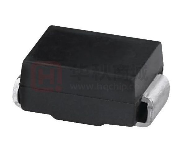


 工商网监
湘ICP备2023018690号
工商网监
湘ICP备2023018690号
