(877) 634-0982
www.digipwr.com
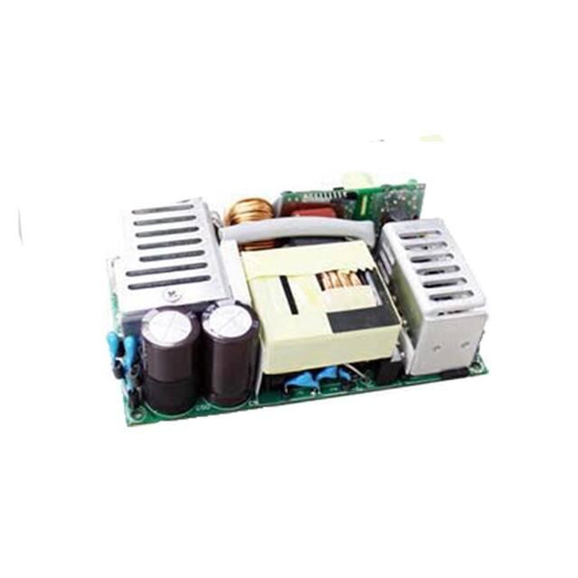
H D M5 0 0 S E R I E S
AC-DC ITE AND MEDICAL SWITCHING PSU
500 WATT
KEY FEATURES
Digital Power’s HDM500 Series are switching power supplies that produce
superior output wattages with natural convection. The series include enclosed,
open fame and U bracket format with output voltage options of 12V, 15V, 24V
and 48V. Featured with compact, low profile footprint, and best-in-class
performance, HDM500 Series are optimal for ITE and Medical Applications.
Designed with energy saving in mind, Digital Power’s HDM500 Series boasts not
only high operating efficiency up to 93%, but also high-power density with full
input range of 90-264Vac.
HDM500 operates over wide temperature range from -30°C to +70°C with
complete protections and certified to UL / IEC / EN 60601 3.1rd Edition & UL /
IEC / EN 60950 AM2 Safety Approvals.
1
�(877) 634-0982
www.digipwr.com
PRODUCT
SPECIFICATION
Enclosed, U Bracket
Switching Power
Supply
•
Remote ON/OFF Function
•
240 Watt with Free Air Convection
•
500 Watt with 30CFM FAN
•
4000VAC Input to Output 2MOPP
Insulation
•
Built-in 12V/0.3A Auxiliary Output
•
Standby 5V@1A with Fan, @0.4A
without Fan
•
High Efficiency up to 93%
•
With P.F.C. Function >0.94
•
Current Share Function for Option
(except for 115)
•
Ultra Compact Size:
HDM500O: 5.03 x 3.0 x 1.38 Inches
HDM500U: 5.5 x 3.25 x 1.6 Inches
HDM500E: 5.5 x 3.25 x 2.42 Inches
HDM500 Series
2
�(877) 634-0982
www.digipwr.com
ELECTRICAL SPECIFICATION - HDM500O SERIES
Model No.
Max Output Wattage (W)
HDM500O-112
Max Output Wattage (W)
Voltage (Note 3)
Input
Output
Protection
Isolation
Physical
Safety
EMC
HDM500O-124
HDM500O-148
Frequency (Hz)
Current (Full load)
Inrush Current (160,000 h @ 25°C (MIL-HDBK-217F)
IEC60068-2-6 (10~500Hz, 2G 10min./1cycle, 60min. each along X, Y, Z
axes)
IEC60068-2-27
5.03 x 3.0 x 1.38 Inches ( 127.8 x 76.2 x 35.0 mm ) Tolerance 0.5 mm
480 g
Free convection / 30 CFM FAN
Others: UL / IEC / EN 60601 3.1rd Edition & UL / IEC / EN 60950 AM2
115:
UL / IEC / EN 60601 3.1rd Edition
EN55011 / conducted class B, Radiated Class A
EN60601-1-2 4th edition
All specifications valid at normal input voltage, full load and +25°C after warm-up time unless otherwise stated.
3
HDM500 Series
�(877) 634-0982
www.digipwr.com
ELECTRICAL SPECIFICATION - HDM500O SERIES
NOTE
1.
Ripple & Noise are measured at 20MHz of bandwidth with ceramic 0.1uF & chemi-con KY 47uF
parallel capacitor.
A 30cm twisted pair of no.18 AWG copper wire is connected to a 47uF and 0.1uF capacitor of
proper polarity and voltage rating. The oscilloscope probe ground led should connect right to
the ground ring of the probe and be as short as possible. The oscilloscope bandwidth should be
at 20MHz and connected to AC ground.
2. Hold-up Time measured at 90% Vout.
3. Please check the derating curve for more details.
4. Main Vout >3% Load, 12V (Aux) / 0.3A., 12V (Aux) need 0.1A Minimum Load, Auxiliary voltage
output ground 10.2~13.3V
5. Strongly recommend to conduct this test with DC Voltage. If customer wishes to test with AC
Voltage, please disconnect all Y-Capacitors from Digital Power power supply.
6. Current Share Board (Optional):
(a.)The output voltage difference of each parallel single element should be less than 0.2V.
(b.)Output power at parallel operation = rated power per unit x number of unit x 90%
(c.)Connect in parallel no more than 2 units.
Please contact Digital Power for advice if more than
HDM500
HDM500
2 is needed.
(d.)Minimum Load Should be 15%.
7. CAUTION: Double pole, neutral fusing.
Disconnect mains before servicing.
4
HDM500 Series
�(877) 634-0982
www.digipwr.com
ELECTRICAL SPECIFICATION - HDM500O SERIES
DERATING
BLOCK DIAGRAM
5
HDM500 Series
�(877) 634-0982
www.digipwr.com
MECHANICAL DIMENSIONS– HDM500O SERIES
Brands
PIN#
Single
Alex
JST
Mating
Mating
Terminal
Terminal
Housing
Housing
─
─
─
─
1
PE
2
3
4
AC IN (N)
NO PIN
AC IN (L)
5
6
+DC OUT Terminal : M5 Pan HD screw in 2 positions.
-DC OUT Torque to 8 lbs-in(90cNm) max
9396-3
SVH-41T96T series VHR-3N
P1.1
Connector Pin (FAN)
Brands
PIN#
Single
F1
+12V
F2
GND
Alex
JST
Mating
Mating
Terminal
Terminal
Housing
Housing
CXCX-T2501 XHP-2
H250-02
Connector Pin (CN1)
Brands
PIN#
Single
C1
-5V SB
C2
+5V SB
C3
GND
C4
DC-OK
C5
-RC
C6
+RC
C7
-S
C8
+S
Cherng Weei
Mating
Housing
Terminal
PHD-H20PHD-T20
2X4P
JST
Mating
Housing
Terminal
PHDR08VS
SPHD001T- P0.5
SXH002TP0.6
6
HDM500 Series
�(877) 634-0982
www.digipwr.com
MECHANICAL DIMENSIONS– HDM500O SERIES
HDM500O with Current Share Function
Brands
Alex
JST
Mating
Mating
Terminal
Terminal
Housing
Housing
─
─
─
─
Connector Pin (CN1)
PIN#
Single
1
PE
2
3
4
AC IN (N)
NO PIN
AC IN (L)
5
6
+DC OUT Terminal : M5 Pan HD screw in 2 positions.
-DC OUT Torque to 8 lbs-in(90cNm) max
9396-3
96T series VHR-3N
SVH-41TP1.1
Connector Pin (FAN)
Brands
PIN#
Single
F1
+12V
F2
GND
Alex
JST
Mating
Mating
Terminal
Terminal
Housing
Housing
CXCX-T2501 XHP-2
H250-02
Brands
SXH002TP0.6
PIN#
Single
C1
-5V SB
C2
+5V SB
C3
GND
C4
DC-OK
C5
-RC
C6
+RC
C7
-S
C8
+S
Cherng Weei
Mating
Housing
Terminal
PHD-H20PHD-T20
2X4P
JST
Mating
Housing
Terminal
PHDR08VS
SPHD001T- P0.5
Connector Pin (CN2)
Brands
PIN#
Single
C1
-S
C2
+S
Cherng Weei
Mating
Housing
CP- H20-02
JST
Terminal
CP- T20B
Mating
Housing
PHR-2
Terminal
SPH002T- P0.5L
7
HDM500 Series
�(877) 634-0982
www.digipwr.com
MECHANICAL DIMENSIONS– HDM500O SERIES
Mating Housing Pin (CN3)
Brands
PIN#
Single
C1
-5V SB
C2
+5V SB
C3
GND
C4
DC-OK
C5
-RC
C6
+RC
Cherng Weei
JST
Connector
Connector
CP-W20-06
B6B-PH-K-S
Connector Pin (CN4)
Brands
Cherng Weei
PIN#
Single
C1
LS
C2
LS
Mating
Housing
CP- H20-02
Terminal
CP- T20B
JST
Mating
Housing
PHR-2
Terminal
SPH002T- P0.5L
FUNCTION DESCRIPITON of CN1 and CN3 (CN3 without C7 and C8 pin)
Pin No.
Function
C1
-5VSB
Description
This pin connects to the negative terminal(-V). Return for DC-OK and -RC signal output.
C2
+5VSB
C3
GND
Stand by voltage output ground 4.2~5.5V, referenced to pin
C1(-5VSB). The maximum load current is 1A with Fan, 0.4A
without Fan..
This pin connects to the negative terminal(-V). Return for DC-OK and -RC signal output.
C4
DC OK
DC-OK Signal is a DC output, referenced to pin C3(DC-OK GND).
C5
-RC
This pin connects to the negative terminal(-V). Return for DC-OK and -RC signal output.
C6
+RC
C7
-S
C8
+S
Turns the output on and off by electrical or dry contact between pin C5 (-RC), Short: Power OFF, Open: Power
ON. The input voltage must be less than 1V in order to disable VOUT and greater than 3.3V (up to 5V) to enable
it.
Negative sensing. The -S signal should be connected to the negative terminal of the load. The -S and +S leads should
be twisted in pair to minimize noise pick-up effect.
Positive sensing. The +S signal should be connected to the positive terminal of the load. The +S and -S leads should be
twisted in pair to minimize noise pick-up effect.
8
HDM500 Series
�(877) 634-0982
www.digipwr.com
MECHANICAL DIMENSIONS– HDM500O SERIES
FUNCTION MANUAL & APPLICATION NOTE
1. DC-OK Signal
Between
DC-OK and GND
3.7~6V
0~1V
Output
Status
ON
OFF
2. Remote Control
It can be turned ON/OFF by using the "Remote Control" function.
Between
+RC and -RC
SW ON (Short)
SW OFF (Open)
Output
Status
OFF
ON
3. +S and -S Sense
Shorter wiring to each unit is recommended, as well as twisting +S and -S in pairs, as shown below
9
HDM500 Series
�(877) 634-0982
www.digipwr.com
ELECTRICAL SPECIFICATION - HDM500U SERIES
Model No.
HDM500U-112
Max Output Wattage (W)
500 W (30CFM FAN)
Others: 190 W (115 VAC) / 200 W (230 VAC)
115:
170 W (115 VAC) / 180 W (230 VAC)
90-264 VAC or 127-370 VDC
47-63 Hz
< 6.3 A max. (115 VAC) / 0.94 at Full Load
12V
15V
24V
±2%
±4% Output Voltage
41.5
33.3
20.8
15.83
11.33
7.91
16.6
12
8.33
Max Output Wattage (W)
Voltage (Note 3)
Frequency (Hz)
Current (Full load)
Input
Inrush Current (160,000 h @ 25°C (MIL-HDBK-217F)
IEC60068-2-6 (10~500Hz, 2G 10min./1cycle, 60min. each along X, Y, Z
axes)
IEC60068-2-27
5.5 x 3.25 x 1.6 Inches ( 139.7 x 82.55 x 40.6 mm ) Tolerance 0.5 mm
580 g
Free convection / 30 CFM FAN
Others: UL / IEC / EN 60601 3.1rd Edition & UL / IEC / EN 60950 AM2
115:
UL / IEC / EN 60601 3.1rd Edition
EN55011 / conducted class B, Radiated Class A
EN60601-1-2 4th edition
All specifications valid at normal input voltage, full load and +25°C after warm-up time unless otherwise stated.
10
HDM500 Series
�(877) 634-0982
www.digipwr.com
ELECTRICAL SPECIFICATION - HDM500U SERIES
NOTE
1.
Ripple & Noise are measured at 20MHz of bandwidth with ceramic 0.1uF & chemi-con KY 47uF
parallel capacitor.
A 30cm twisted pair of no.18 AWG copper wire is connected to a 47uF and 0.1uF capacitor of
proper polarity and voltage rating. The oscilloscope probe ground led should connect right to
the ground ring of the probe and be as short as possible. The oscilloscope bandwidth should be
at 20MHz and connected to AC ground.
2. Hold-up Time measured at 90% Vout.
3. Please check the derating curve for more details.
4. Main Vout >3% Load, 12V (Aux) / 0.3A., 12V (Aux) need 0.1A Minimum Load, Auxiliary voltage
output ground 10.2~13.3V
5. Strongly recommend to conduct this test with DC Voltage. If customer wishes to test with AC
Voltage, please disconnect all Y-Capacitors from Digital Power power supply.
6. Current Share Board (Optional):
(a.)The output voltage difference of each parallel single element should be less than 0.2V.
(b.)Output power at parallel operation = rated power per unit x number of unit x 90%
(c.)Connect in parallel no more than 2 units. Please contact Digital Power for advice if more
than 2 is needed.
HDM500
HDM500
(d.)Minimum Load Should be 15%.
7. CAUTION: Double pole, neutral fusing.
Disconnect mains before servicing.
11
HDM500 Series
�(877) 634-0982
www.digipwr.com
ELECTRICAL SPECIFICATION - HDM500U SERIES
DERATING
BLOCK DIAGRAM
12
HDM500 Series
�(877) 634-0982
www.digipwr.com
MECHANICAL DIMENSIONS – HDM500U SERIES
A= For fixture to chassis only
A=M3x0.5P
B=For fixture to pcb/chassis
only
B=M3x0.5P
Brands
Alex
JST
Single
Mating
Housing
A.B
PE
─
1
AC IN (N)
2
NO PIN
3
AC IN (L)
4
+DC OUT Terminal : M5 Pan HD screw in 2 positions.
-DC OUT Torque to 8 lbs-in(90cNm) max
PIN#
5
9396-3
Mating
Terminal
Housing
─
ASSEMBLY INSTRUCTIONS
U Case T=1.5mm
Customer is advised to screw into the
threads no more than 1.5mm
Terminal
─
─
96T series VHR-3N
SVH-41T-P1.1
Chassis of
HDM500U
Series
Connector Pin (CN1)
Brands
PIN#
Single
C1
-5V SB
C2
+5V SB
C3
GND
C4
DC-OK
C5
-RC
C6
+RC
C7
C8
Cherng Weei
Mating
Housing
Terminal
JST
Mating
Housing
T=1.5mm
Terminal
Connector Pin (FAN)
PHD-H20PHD-T20
2X4P
PHDR08VS
SPHD001T- P0.5
Brands
PIN#
Single
-S
F1
+12V
+S
F2
GND
Alex
Mating
Housing
JST
Terminal
CXCX-T2501
H250-02
Mating
Housing
Terminal
XHP-2
SXH002TP0.6
13
HDM500 Series
�(877) 634-0982
www.digipwr.com
MECHANICAL DIMENSIONS– HDM500U SERIES
HDM500U with Current Share Function
A= For fixture to chassis only
A=M3x0.5P
B=For fixture to pcb/chassis only
B=M3x0.5P
Brands
ASSEMBLY INSTRUCTIONS
U Case T=1.5mm
Customer is advised to
screw into the threads no
more than 1.5mm
Alex
JST
PIN#
Single
Mating
Housing
Terminal
Mating
Housing
Terminal
A.B
PE
─
─
─
─
1
AC IN (N)
2
NO PIN
3
AC IN (L)
4
+DC OUT Terminal : M5 Pan HD screw in 2 positions.
-DC OUT Torque to 8 lbs-in(90cNm) max
5
9396-3
96T series VHR-3N
SVH-41T-P1.1
Connector Pin (FAN)
Chassis of
HDM500U
Series
Brands
T=1.5mm
Alex
PIN#
Single
F1
+12V
F2
GND
Mating
Housing
JST
Terminal
CX- H250- CX- T2501
02
Mating
Housing
Terminal
XHP-2
SXH-002TP0.6
14
HDM500 Series
�(877) 634-0982
www.digipwr.com
MECHANICAL DIMENSIONS– HDM500U SERIES
Mating Housing Pin (CN3)
Connector Pin (CN1)
Cherng Weei
Brands
Mating
Housing
PIN#
Single
C1
-5V SB
C2
+5V SB
C3
GND
C4
DC-OK
C5
-RC
C6
+RC
C7
-S
C8
+S
Terminal
PHD-H20PHD-T20
2X4P
Connector Pin (CN2)
Brands
PIN#
Single
C1
C2
-S
+S
Brands
JST
Mating
Housing
PHDR08VS
Terminal
PIN#
Single
C1
-5V SB
C2
+5V SB
C3
GND
C4
DC-OK
C5
-RC
C6
+RC
SPHD001T- P0.5
Cherng Weei
Mating
Housing
CPH20-02
Cherng Weei
JST
Connector
Connector
CP-W20-06
B6B-PH-K-S
JST
Terminal
CP- T20B
Mating
Housing
PHR-2
Terminal
SPH002T- P0.5L
Connector Pin (CN4)
Brands
Cherng Weei
PIN#
Single
C1
LS
C2
LS
Mating
Housing
CP- H20-02
JST
Terminal
Mating
Housing
Terminal
CP- T20B
PHR-2
SPH002TP0.5L
FUNCTION DESCRIPITON of CN1 and CN3 (CN3 without C7 and C8 pin)
Pin No.
Function
Description
C1
-5VSB
This pin connects to the negative terminal(-V). Return for DC-OK and -RC signal output.
C2
+5VSB
Stand by voltage output ground 4.2~5.5V, referenced to pin C1(5VSB). The maximum load current is 1A with Fan, 0.4A without Fan..
C3
GND
This pin connects to the negative terminal(-V). Return for DC-OK and -RC signal output.
C4
DC OK
DC-OK Signal is a DC output, referenced to pin C3(DC-OK GND).
C5
-RC
This pin connects to the negative terminal(-V). Return for DC-OK and -RC signal output.
C6
+RC
Turns the output on and off by electrical or dry contact between pin C5 (-RC), Short: Power OFF, Open: Power ON. The
input voltage must be less than 1V in order to disable VOUT and greater than 3.3V (up to 5V) to enable it.
C7
-S
Negative sensing. The -S signal should be connected to the negative terminal of the load. The -S and +S leads should be
twisted in pair to minimize noise pick-up effect.
C8
+S
Positive sensing. The +S signal should be connected to the positive terminal of the load. The +S and -S leads should be twisted
in pair to minimize noise pick-up effect.
15
HDM500 Series
�(877) 634-0982
www.digipwr.com
MECHANICAL DIMENSIONS– HDM500U SERIES
FUNCTION MANUAL & APPLICATION NOTE
1. DC-OK Signal
Between
DC-OK and GND
3.7~6V
0~1V
Output
Status
ON
OFF
2. Remote Control
It can be turned ON/OFF by using the "Remote Control" function.
Between
+RC and -RC
SW ON (Short)
SW OFF (Open)
Output
Status
OFF
ON
3. +S and -S Sense
Shorter wiring to each unit is recommended, as well as twisting +S and -S in pairs, as shown below
16
HDM500 Series
�(877) 634-0982
www.digipwr.com
ELECTRICAL SPECIFICATION - HDM500E SERIES
Model No.
Max Output Wattage (W)
Voltage (Note 3)
Frequency (Hz)
Current (Full load)
Inrush Current (160,000 h @ 25°C (MIL-HDBK-217F)
IEC60068-2-6 (10~500Hz, 2G 10min./1cycle, 60min. each along X, Y, Z axes)
IEC60068-2-27
5.5 x 3.25 x 2.42 Inches ( 139.7 x 82.55 x 61.4 mm ) Tolerance 0.5 mm
690 g
Approval
Conducted and Radiated EMI
EMS
Others: UL / IEC / EN 60601 3.1rd Edition & UL / IEC / EN 60950 AM2
115:
UL / IEC / EN 60601 3.1rd Edition
EN55011 / conducted class B, Radiated Class A
EN60601-1-2 4th edition
All specifications valid at normal input voltage, full load and +25°C after warm-up time unless otherwise stated.
17
HDM500 Series
�(877) 634-0982
www.digipwr.com
ELECTRICAL SPECIFICATION - HDM500E SERIES
NOTE
1.
Ripple & Noise are measured at 20MHz of bandwidth with ceramic 0.1uF & chemi-con KY 47uF
parallel capacitor.
A 30cm twisted pair of no.18 AWG copper wire is connected to a 47uF and 0.1uF capacitor of
proper polarity and voltage rating. The oscilloscope probe ground led should connect right to
the ground ring of the probe and be as short as possible. The oscilloscope bandwidth should be
at 20MHz and connected to AC ground.
2. Hold-up Time measured at 90% Vout.
3. Please check the derating curve for more details.
4. Main Vout >3% Load, 12V (Aux) / 0.3A., 12V (Aux) need 0.1A Minimum Load, Auxiliary voltage
output ground 10.2~13.3V
5. Strongly recommend to conduct this test with DC Voltage. If customer wishes to test with AC
Voltage, please disconnect all Y-Capacitors from Digital Power power supply.
6. Current Share Board (Optional):
(a.)The output voltage difference of each parallel single element should be less than 0.2V.
(b.)Output power at parallel operation = rated power per unit x number of unit x 90%
(c.)Connect in parallel no more than 2 units. Please contact Digital Power for advice if more
than 2 is needed.
HDM500
HDM500
(d.)Minimum Load Should be 15%.
7. CAUTION: Double pole, neutral fusing.
Disconnect mains before servicing.
18
HDM500 Series
�(877) 634-0982
www.digipwr.com
ELECTRICAL SPECIFICATION - HDM500E SERIES
DERATING
BLOCK DIAGRAM
19
HDM500 Series
�(877) 634-0982
www.digipwr.com
MECHANICAL DIMENSIONS – HDM500E SERIES
A= For fixture to
chassis only
A=M3x0.5P
B=For fixture to
pcb/chassis only
B=M3x0.5P
Brands
Alex
Single
Mating
Housing
A.B
PE
─
1
AC IN (N)
2
NO PIN
PIN#
9396-3
JST
Terminal
Mating
Housing
Terminal
─
─
─
96T series VHR-3N
SVH-41T-P1.1
3
AC IN (L)
4
+DC OUT Terminal : M5 Pan HD screw in 2 positions.
-DC OUT Torque to 8 lbs-in(90cNm) max
5
Chassis of
HDM50E
Series
Connector Pin (CN1)
Cherng Weei
Brands
PIN#
Single
C1
-5V SB
C2
+5V SB
Mating
Housing
Terminal
ASSEMBLY INSTRUCTIONS
U Case T=1.5mm
Customer is advised to screw into the
threads no more than 1.5mm
JST
Mating
Housing
Terminal
PHDR08VS
SPHD-001TP0.5
T=1.5mm
C3
GND
C4
DC-OK
C5
-RC
C6
+RC
PIN#
Single
C7
-S
F1
+12V
F2
GND
C8
+S
Connector Pin (FAN)
PHXD-H20PHD-T20
2X4P
Brands
Alex
JST
Mating
Mating
Terminal
Terminal
Housing
Housing
CXCXH250-02 T2501
XHP-2
SXH002TP0.6
20
HDM500 Series
�(877) 634-0982
www.digipwr.com
MECHANICAL DIMENSIONS– HDM500E SERIES
HDM500E with Current Share Function
A= For fixture to chassis only
A=M3x0.5P
B=For fixture to pcb/chassis only
B=M3x0.5P
ASSEMBLY INSTRUCTIONS
U Case T=1.5mm
Customer is advised to
screw into the threads no
more than 1.5mm
Chassis of
HDM500E
Series
Brands
JST
PIN#
Single
Mating
Housing
Terminal
Mating
Housing
Terminal
A.B
PE
─
─
─
─
1
AC IN (N)
2
NO PIN
3
AC IN (L)
4
+DC OUT Terminal : M5 Pan HD screw in 2 positions.
-DC OUT Torque to 8 lbs-in(90cNm) max
5
T=1.5mm
Alex
9396-3
96T series VHR-3N
SVH-41T-P1.1
Connector Pin (FAN)
Brands
PIN#
Single
F1
+12V
F2
GND
Cherng Weei
Mating
Housing
CXH250-02
JST
Terminal
Mating
Housing
Terminal
CXT2501
XHP-2
SXH002TP0.6
21
HDM500 Series
�(877) 634-0982
www.digipwr.com
MECHANICAL DIMENSIONS– HDM500E SERIES
Connector Pin (CN1)
Mating Housing Pin (CN3)
Cherng Weei
Brands
PIN#
Single
C1
Mating
Housing
JST
Mating
Housing
Terminal
Terminal
Brands
PIN#
Single
-5V SB
C1
-5V SB
C2
+5V SB
C2
+5V SB
C3
GND
C4
DC-OK
C3
GND
C5
-RC
C4
DC-OK
C6
+RC
C7
-S
C5
-RC
C8
+S
C6
+RC
PHD-H20PHD-T20
2X4P
PHDR08VS
SPHD001T- P0.5
Cherng Weei
JST
Connector
Connector
CP-W20-06
B6B-PH-K-S
Connector Pin (CN2)
Brands
Cherng Weei
PIN#
Single
C1
-S
C2
+S
Mating
Housing
Terminal
CP- H20-02
CP- T20B
JST
Mating
Housing
Terminal
SPH002T- P0.5L
PHR-2
Connector Pin (CN4)
Brands
Cherng Weei
PIN#
Single
C1
LS
C2
LS
Mating
Housing
CP- H20-02
JST
Terminal
Mating
Housing
Terminal
CP- T20B
PHR-2
SPH002TP0.5L
FUNCTION DESCRIPITON of CN1 and CN3 (CN3 without C7 and C8 pin)
Pin No.
Function
C1
-5VSB
Description
This pin connects to the negative terminal(-V). Return for DC-OK and -RC signal output.
C2
+5VSB
Stand by voltage output ground 4.2~5.5V, referenced to pin C1(5VSB). The maximum load current is 1A with Fan, 0.4A without Fan..
C3
GND
This pin connects to the negative terminal(-V). Return for DC-OK and -RC signal output.
C4
DC OK
DC-OK Signal is a DC output, referenced to pin C3(DC-OK GND).
C5
-RC
This pin connects to the negative terminal(-V). Return for DC-OK and -RC signal output.
C6
+RC
Turns the output on and off by electrical or dry contact between pin C5 (-RC), Short: Power OFF, Open: Power ON. The
input voltage must be less than 1V in order to disable VOUT and greater than 3.3V (up to 5V) to enable it.
C7
-S
Negative sensing. The -S signal should be connected to the negative terminal of the load. The -S and +S leads should be
twisted in pair to minimize noise pick-up effect.
C8
+S
Positive sensing. The +S signal should be connected to the positive terminal of the load. The +S and -S leads should be twisted
in pair to minimize noise pick-up effect.
22
HDM500 Series
�MECHANICAL DIMENSIONS – HDM500E SERIES
FUNCTION MANUAL & APPLICATION NOTE
1.
DC-OK Signal
Between
DC-OK and GND
3.7~6V
0~1V
Output
Status
ON
OFF
2. Remote Control
It can be turned ON/OFF by using the "Remote Control" function.
Between
+RC and -RC
SW ON (Short)
SW OFF (Open)
Output
Status
OFF
ON
3. +S and -S Sense Shorter wiring to each unit is recommended,
as well as twisting +S and -S in pairs, as shown below
Digital Power Corporation
1635 S Main Street.
Milpitas, CA 95035 USA
T: (877) 634-0982 sales@digipwr.com
F: (510) 657-6634
www.digipwr.com
Digital Power Corporation designs and manufactures full custom,
value added and standard comprehensive power solutions for the
most demanding applications in the defense, healthcare, telecom,
and industrial markets.
23
HDM500 Series
�


 工商网监
湘ICP备2023018690号
工商网监
湘ICP备2023018690号
