03
EC
M
U
-M
M
EC
I
LT
PANEL
PCB SWITCHES
22
3F
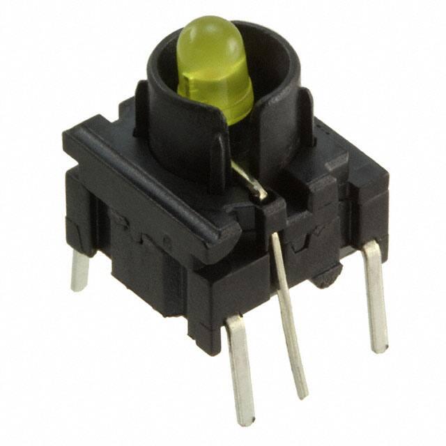
Multimec™ 3F
High performance tactile switches •
robust
DISTINCTIVE FEATURES
10 x 10 mm; h=10.4 mm
Illuminated RAS option
Slip-on cap retention system - great for custom caps
ENVIRONMENTAL SPECIFICATIONS
• Sealing : IP67 according to IEC 60529
• �Working and storage temperature :
- non-illuminated : -40 °C/+160 °C (-40 °F to +320 °F)
- illuminated : -40 °C /+85 °C (-40 °F to +185 °F)
• �Soldering :
- through-hole : IEC 60068-2-20 8
- surface mount : JEDEC J-STD-020E
ELECTRICAL SPECIFICATIONS
• �Recommended load :
- Gold contacts : 0.5µ-50 mA 24 VDC
- Silver contacts : 0.5-50 mA 24 VDC
• Contact resistance : 10 MΩ
• Contact bounce : 10,000,000 cycles
• Terminals : SnCu + 2 µNI + 3 µSn100
The company reserves the right to change specifications without notice.
All tolerance if not otherwise specified ±0.2 mm.
• �Max. actuation force : 100 N for 10 sec
1
�6,4
10,4
High performance tactile switches •
robust
3F - SMD
14
Ø 6,5
10
6,4
10,4
10
7,62
14
0,8
Ø 6,5
6,4
10,4
0,8
7,62
3F - TH
Min 10,16
Max 12,5
0,3
Ø 6,5
10
6,4
10,4
10
0,8
0,3
Min 10,16
Max 12,5
7,62
Ø 6,5
0,8
7,62
3F - TH W/LED
10
10
2,54
2,54
3F - RAS
10
7,62
12
5,08
7,62
2
10
7,62
12
PCB SWITCHES
Multimec™ 3F
5,08
7,62
�PANEL
PCB SWITCHES
Multimec™ 3F
5,5
6,0
10
12
High performance tactile switches •
robust
5,08
2,54
3F - RAS W/LED
7,62
20,1
6,0
10
12
±0,3
17,8
5,5
7,62
5,08
2,54
2,54
7,62
20,1
±0,3
17,8
PCB LAYOUT & CIRCUIT DIAGRAM
7,62
2,54
4
2,5
Ø1,0(3x)
3
Ø1,0(3x)
2,54
1
3
Ø1,0(3x)
2,54
7,62
7,62
5,08
Ø1,0(4x)
7,62
5,08
7,62
3 +3
2,5
5,08
+
Ø1,0(4x)
7,62
7,62
5,08
7,62
2,54
ø1.0 (4X)
RAS bi-color illuminated
7,62
2,54
ø1.0 (4X)
3
2,54
4
7,62
Ø1,0(4x)
3
+3
5,08
7,62
2,54
1
5,08
7,62
3
1,2
3
3 +34
2,5
2,54
Ø 0,9
7,62 [0,300]
4
2,54 [0,100]
4
+
7,62
1
-
7,62
1 1
1
7,62
3
12,50
-2
1
-
5,08
1,2
2,5
1
-2
RAS illuminated
7,62
10,16
2
7,62
2
10,16 [0,400]
2,54
2,54 [0,100]
1
Ø 0,9
RAS
TH bi-color illuminated
0
44
33
2,5
Ø
0,9
12,50
10,16 [0,400]
7,62
2
2,54
4
1
7,62 [0,300]
4
3
1
7,62
3
2,5
Ø 0,9
-22
11
2,54
44
3
Ø 0,9
10,16
12,50
2
1,2
7,62
1,2
4
2
7,62
7,62
1
1,2
1
7,62
7,62
7,62
22
2,54 [0,100]
10,16
12,50
10,16
12,50
1
7,62
10,16
2
TH illuminated
1,2
2,54 [0,100]
SMD non-ill.
5,08
TH Non-ill.
�PCB SWITCHES
Multimec™ 3F
High performance tactile switches •
robust
BUILD YOUR PART NUMBER
ILLUMINATED
3F
MOUNTING
SERIES
TH9
LED
through-hole
OPTIONAL
06
blue
Q
quiet contact
20
green
G
gold contacts
40
yellow
RAS
65
white
80
red
2040
green/yellow
8020
red/green
8040
red/yellow
24
high intensity green
46
high intensity yellow
87
high intensity red
right angle
NON-ILLUMINATED
3F
MOUNTING
SERIES
TH9
through-hole
SH9
surface mount
OPTIONAL
Q
quiet contact
RAS
right angle
(with TH only)
R
tape & reel
(with SMD only)
G
gold contacts
ABOUT THIS SERIES
Caps and accessories : for the full range of accessories for Multimec™ 3F please see the website.
4
�High performance tactile switches •
robust
OPERATING FORCE
TAPE & REEL
Tape and reel is available for the parts listed and has the
following specifications
FORCE
10
• Reel diameter: Ø330 mm
9
• Tape width: 24 mm
• Pitch: see list
8
• Tape and reel material: antistatic or better
• Quantity per reel: see list
7
ORDERING CODE
PITCH
QUANTITY
PER REEL
3FSH9
3FSH9R
20
250
6
F(N)
PART NO.
5
3,5N
3.5
N
4
3
2
1
TRAVEL
0
0
0,2
0,4
0,6
0,8
1
L(mm)
1,2
1,4
1,6
1,8
2
MOUNTING
MOUNTING TOOLS FOR MULTIMEC™ THROUGH-HOLE SWITCHES
Part No. 9861000
1
2
3
4
5
5
PANEL
PCB SWITCHES
Multimec™ 3F
�PCB SWITCHES
Multimec™ 3F
High performance tactile switches •
robust
MOUNTING (CONTINUED)
SPACE REQUIREMENT - MATRIX MOUNTING
Through-hole (TH)
Surface mount (SMD)
MULTIMEC™ SPACING EXAMPLES
13.6
13.6
12.7
12.7
1V+1T+1V
1N+1N+1N
SPACE REQUIREMENT - SWITCH/CAP
Cap dimensions
Switch spacing
Panel cut-out
6
CAP SERIES
RECOMMENDED
MIN.SWITCH SPACING AxB
NOMINAL CAP DIMENSION
WxH
RECOMMENDED
MIN. PANEL CUT-CUT
1D/1E/1F
1GA
12.7x11.3
Ø9.6
Ø10.0
12.7x11.3
Ø11.0
Ø11.4
1GC
15.3x15.3
Ø15.0
Ø15.4
1K/1KB/1KC
14.6x14.6
14.3x14.3
14.7x14.7
1N
13.6x11.3
Ø9.8/ 14.9
Ø10.2/15.1
1P/ 1Q/1R
12.8x10.3
6.5x12.5
7.0x13.0, R max. 1.0
1S
12.7x10.3
Ø6.5
Ø7.0
1T
12.7x12.3
10.6x10.6
11.0x11.0
1U
12.7x12.3
Ø10.6
Ø11.0
1V
15.95x12.1
10.6x13.25
11.0x13.65
1WA
14.2x10.3
12.5x6.5
12.9x6.9
1WD
16.9X10.3
15.2x8.0
15.6x8.4
1X
12.7x10.3
9.4x7.4
9.8x7.9
1ZC
14.6x14.6
Ø14.3
Ø14.7
�High performance tactile switches •
robust
LED COMPONENT SPECIFICATIONS
LED COMPONENT SPECIFICATIONS
Color
B
G
Y
W
R
G/Y
R/G
R/Y
G
Y
R
Color Codes
06
20
40
65
80
2040
8020
8040
24
46
87
120
120
60
110
100
100/60
100/100
75/75
60
60
60
ABSOLUTE MAXIMUM RATINGS (Ta=25°C)
Power
mW
Current forward
mA
30
30
20
30
30
30/20
30/30
30/30
25
25
25
Forward peak current
mA
150
90**
80**
100
90**
120/80
120/120
160/140
60
60
60
Voltage reverse
V
5
3
5
5
3
5
5
5
5
5
5
Operating
temperature
°C
-40/+85
-55/+100
-40/+85
-55/+100
-55/+100
-55/+100
-40/+85
-40/+85
-40/+85
-40/+85
Storage temperature
°C
-40/+85
-55/+100
-40/+100
-55/+100
-55/+100
-55/+100
-40/+85
-40/+100
-40/+100
-40/+100
Soldering temperature
°C
260 for max 3 sec
260 for max 2 sec
260 for max 5 sec
ELECTRICAL-OPTICAL CHARACTERISTICS (Ta=25°C)
Voltage forward
Typ. V
3.3
2.1
2.1
3.0
2.0
2.1/2.1
2.0/2.1
2/2.1
2.0*
2.0
2.0***
Max. V
4.0
2.6
2.6
4.0
2.6
2.6/2.4
2.6/2.6
2.5/2.5
2.4*
2.4
2.4***
Current reverse (VR=5V)
µA
Max. 50
100
100
100
100
100
100
2
10
10
10
Wave length
nm
460
569
588
NA
625
565
621/569
617/588
573
589
624
25
40
35
NA
40
30/35
40/30
45/35
20
NA
20
Spread angle
Spread
degree
nm
30
60
60
25
60
80/60
200
60
100
40
40
Luminous Intensity
Min. mcd
900
5.6
1.7
715
2.5
3.7/2.5
2.2/2.2
6/4
10
630
400
5.6
max
2850
8.7
12.6/8.7
4.8/4.8
14/8
20
1250
800
Typ. mcd
Orientation
1600
12.6
The longer pin is the anode, the shorter is the cathode.
For bi-color LEDs the anode for the first color (ex. 8020) is the longer pin.
*/F=20mA, **1/10 duty cycles 0.1ms pulse width, ***/F=50mA, ****Luminous Flux mlm
7
PANEL
PCB SWITCHES
Multimec™ 3F
�PCB SWITCHES
Multimec™ 3F
High performance tactile switches •
robust
USAGE GUIDELINES
HOW TO GET THE BEST RESULTS WITH
MEC SWITCHES ?
These guidelines are offered to users of MEC Switches as
an aid to ensure successful and reliable switch operation.
Please see the technical specifications for details on operating and storage temperatures and soldering guidelines
to make sure you select the best switch for your application. When reflow soldering is taking place, MEC strongly
recommend that the temperature profile is analyzed and
compared with the temperature rating of the switch. It is
also important to monitor the accumulated heat buildup
from both the pre-heat zones and the solder zone.
Most standard accessories for multimec™ 3 series switches
are made from ABS plastic with a maximum operating
temperature of 65 °C. It is strongly recommended that accessories are mounted after soldering of the switch.
If this is not possible care must be taken not to overheat
the accessories during the soldering process. The 1S and
1GA/1GC caps are, however, made of high temperature
materials and will meet the same temperature specifications as the switches. For accessories made from other
plastic materials please see multimec™ 3 cap & bezel
technical specifications.
offers a high level of sealing, however, with aqueous
solvent solutions care must be taken to avoid the worst
case situation with water jets, complete immersion into
a liquid with a temperature below the board or surface
tension reducing additives.
Recommended cleaning methods are demineralized
water. Any surface tension reducing agents, such as
soap, must not be used as they risk causing a potential leakage of the switch.
SOLDERING - THROUGH HOLE
VERSIONS
Hand soldering: max. 350 °C for max. 3 sec
Wave soldering: heat built up in the switch during
pre-heating and soldering must not exceed the
maximum operating temperature of the switch. Peak
temperature must not exceed 260 °C, and soldering
time is max 10 sec. (IEC 60068-2-20 8)
SOLDERING - SURFACE MOUNT
VERSIONS
LEDs have their own temperature specifications. When
fitted in a 3F switch the LED will determine the max. operating temperature, i.e. 3FTH924 has an upper temperature
limit of 85 °C!
For all methods - infrared, convection and vapor
phase. The upper limit 240 °C/40 sec must be observed. The soldering temperature profile must have
moderate temperature gradients. (JEDEC J-STD020E)
MOUNTING AND DISMOUNTING
ROHS COMPLIANCE
If switches are to be mounted in rows it is essential that
the recommendations regarding spacing are followed. PC
board thickness should be 1.4 ±0.2 mm and terminal hole
diameter should be 0.9 mm.
As of 1 July 2006 MEC has completed the conversion
to RoHS compliance. For more info please see our
homepage www.apem.com
All multimec™ caps and bezels are easily slid onto the switch
modules and can be changed at a later time .
TEMPERATURE LIMITS
Care must be taken when inserting the 3FT switch and
LED assembly into the PC board. Do not press direct on
the LED. This will force the LED down into the actuator
and risks to cause the switch contacts to remain in the
closed position. To correct the fault, the LED must be raised
slightly and centered in the actuator to assure unrestricted
movement of the actuator.
Switch
LEDs
Accessories
A mounting tool is available for through hole multimec 3
series switches.
™
SOLDERING AND CLEANING
MULTIMEC™ 3 SERIES
Multimec™ 3 series switches are fully sealed to IP67 specifications to prevent solder flux and aqueous based cleaning
solutions from entering the switch and contaminating the
contacts. The switches can be placed on the PC board with
other components and reflow soldered. Multimec™ 3 series
8
160 °C
80/85/100 °C
65/85/160 °C
PACKAGING
Multimec™ 3 series switches are packed in rigid
tubes of 50 pieces each.
A box contains 1.000 pcs.
The surface mount versions of multimec™ 3 series
switches with a height up to 12.5 mm can also be
delivered on tape/reel.
Each reel contains 250/500 pcs.
Right angle swithces are packed in trays.
A tray contains 100 pcs.
�


 工商网监
湘ICP备2023018690号
工商网监
湘ICP备2023018690号
