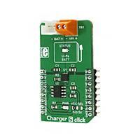
Charger 5 click
PID: MIKROE-2848
Weight: 24 g
Charger 5 click is designed to charge Lithium-Ion and Lithium-Polymer batteries. Besides the
overvoltage and undervoltage protection, reverse discharge and overtemperature protection,
automatic recharge and end of charge safety timer, the click also introduces the fast charging
feature to the line of click board™ charger products. Charger 5 click uses a programmable digital
potentiometer for adjusting the fast charging constant current, which can be set from 100 mA to
950 mA, via the SPI interface.
Charger 5 click carries the MCP73113, a single-cell Li-Po/Li-Ion battery charge IC
from Microchip, along with the digital potentiometer chip labeled as MCP4161, from the same
company. This click can be used to easily and securely charge and fast-charge batteries on many
different devices that use 3.7V Li-Po/Li-Ion batteries.
�How does it work?
Charger 5 click features two integrated circuits, both made by Microchip. One of them is the
MCP73113, a single-cell battery charger equipped with many features, optimized for charging of
the Li-Po/Li-Ion batteries. The constant charging current on the MCP73113 device is set by a
resistor, connected between the PROG pin and the VCC, but instead using the conventional
resistor, Charger 5 click employs the MCP4161 digital potentiometer IC, which allows setting
the constant charging current via the SPI interface. This way, the constant charging current can
be set from 100mA to 950mA.
The MCP73113 charger IC features a plethora of different protections and optimizations so that
the charging process remains perfectly safe and efficient. The undervoltage protection shuts the
charger circuit down in case the connected input voltage is below the threshold value. The
overvoltage protection will also put the device in the shutdown mode if the input voltage is
greater than the threshold value. Also, the connected input voltage should be 150mV greater than
the battery voltage or else it will remain in power down state. This prevents the battery draining
in case there's no input voltage. Therefore, the input voltage range should stay between 5V and
6.5V. The device is resistant to voltage spikes up to 18V on its input connector, but for a proper
operation, the input voltage should stay in the recommended voltage range.
The connected battery voltage is constantly monitored. If it drops below the charging threshold
and if all the other input voltage charging conditions are met, the charging process will start.
When the battery is charged to the factory set threshold, the charging will be stopped to prevent
battery overcharging. Charging threshold for the MCP73113 charger IC used on this click is set
to 4.2V.
If a Li-Ion battery is discharged to below 3V, it has to be pre-charged with around 10% of the
full charge current. This means that the charging current, in this case, will be 10% of the fast
charging current set by the MCP4161 digital potentiometer.
�Charger 5 click detects short circuit on the battery connector. The short circuit is also reported in
case of a faulty battery cell. If such event occurs, the charger will enter the shutdown mode. The
MCP73113 charger IC features thermal management too, which regulates the charging current,
based on the die temperature. If the IC die is heated over 150°C, the device will be shut down.
The onboard SMD jumper selector is used to select voltage for the digital potentiometer IC and
SPI logic levels. There are also two onboard connectors. One connector is a screw terminal used
to connect the external power supply (5V to 6.5V). The other connector is the Li-Po/Li-Ion
battery 2.54mm header connector. This is the standard battery connector used for easy
connection of Li-Po/Li-Ion batteries, like batteries that can be found in the MikroElektronika
shop.
Specifications
Type
Battery charger
Applications
Charger 5 click can be used for fast and secure charging Li-Po/Li-ion 3.7V batteries, used
in wide range of battery powered applications.
On-board
modules
MCP 73113, a single-cell Li-Ion/Li-Polymer battery charge management controller with
input overvoltage protection, MCP 4161, an 8-bit SPI digital POT with non-volatile
memory
Key Features
Charger 5 click features many different options and algorithms optimized for safe and
efficient charging of the Li-Po and Li-ion batteries. It has the fast charging feature, with
user defined fast charging constant current, up to 950mA.
Interface
SPI
Input Voltage 3.3V or 5V
Click board
size
M (42.9 x 25.4 mm)
Pinout diagram
This table shows how the pinout on Charger 5 click corresponds to the pinout on the
mikroBUS™ socket (the latter shown in the two middle columns).
�Notes
Pin
Pin
Notes
NC
1 AN
PWM
16
NC
NC
2 RST
INT
15
NC
SPI CS
CS
3 CS
RX
14
NC
SPI Clock
SCK
4 SCK
TX
13
NC
NC
5 MISO
SCL
12
NC
SPI Data In
SDI
6 MOSI
SDA
11
NC
Power Supply
+3.3V
7 3.3V
5V
10
+5V
Power Supply
Ground
GND
8 GND
GND
9
GND
Ground
Charger 5 click electrical specifications
Description
Input Voltage Range
Current Output
Min Typ Max Unit
4
5
100
6.5
V
950 mA
Operating Ambient Temperature -40
85
°C
Note: The maximum input voltage that the click can withstand is 16V, but it won't operate over
6.5V.
Onboard settings and indicators
Label Name Default
LD1
PWR
LD2 STATUS
J1
BAT
Description
-
Power LED indicator
-
Battery charging status LED
-
Battery connector
�TB1
VIN
JP1 VCC SEL
Left
Input voltage connector
Power supply voltage selection: Left position 3V3, right position 5V
Software support
We provide a library for Charger 5 click on our LibStock page, as well as a demo application
(example), developed using MikroElektronika compilers. The demo can run on all the main
MikroElektronika development boards.
Library description
Key functions:
uint8_t charger5_writeReg(uint8_t register_address, uint16_t transfer_data)-
Function writes to the click's registers
uint16_t charger5_readReg(uint8_t register_address)- Function reads from click's
registers
uint8_t charger5_incrementWiper(uint8_t register_address, uint8_t
numberOfSteps)- Function increments value of the click's registers
uint8_t charger5_decrementWiper(uint8_t register_address, uint8_t
numberOfSteps)- Function decrements value of the click's registers
uint8_t charger5_setCurrent(uint8_t register_address, uint16_t transfer_data)-
Function sets current value of the selected wiper to both, volatile and not volatile, memory
locations
Example description
•
•
•
System Initialization - Initializes peripherals and pins.
Application Initialization - Initializes click driver.
Application Task - Demonstrates the use of driver functions. It will set the charging current up to
500 mA, then decrements that value, and then increments it.
applicationTask()
{
mikrobus_logWrite( "Setting value of current to 500mA", _LOG_LINE );
charger5_setCurrent(_CHARGER5_WIPER0_VOL, _CHARGER5_500MA_CURRENT);
Delay_ms(2000);
mikrobus_logWrite( "Decrementing value of wiper by 5 steps", _LOG_LINE );
charger5_decrementWiper(_CHARGER5_WIPER0_VOL, _CHARGER5_5_STEPS);
�Delay_ms(2000);
mikrobus_logWrite( "Incrementing value of wiper by 2 steps", _LOG_LINE );
charger5_incrementWiper(_CHARGER5_WIPER0_VOL, _CHARGER5_2_STEPS);
}
The full application code, and ready to use projects can be found on our LibStock page.
Additional notes and information
Depending on the development board you are using, you may need USB UART click, USB
UART 2 click or RS232 click to connect to your PC, for development systems with no UART to
USB interface available on the board. The terminal available in all MikroElektronika compilers,
or any other terminal application of your choice, can be used to read the message.
mikroSDK
This click board is supported with mikroSDK, the MikroElektronika Software Development Kit.
To download mikroSDK visit LibStock. For more information about SDK, visit the official page.
Downloads
mikroBUS™ standard specification
LibStock: Charger 5 click library
MCP73113 datasheet
MCP4161 datasheet
Charger 5 click schematic
https://www.mikroe.com/charger-5-click 1-15-18
�


 工商网监
湘ICP备2023018690号
工商网监
湘ICP备2023018690号
