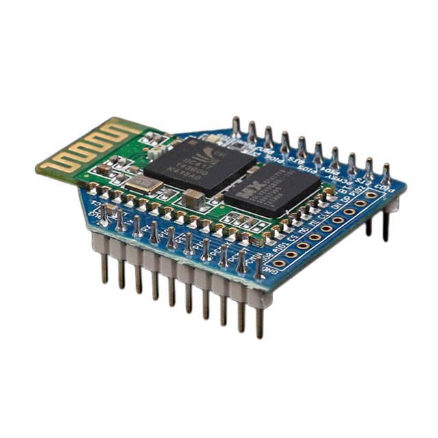
Bluetooth Bee v2.0
Bluetooth Bee is an easy to use Bluetooth SPP module compatible with existing Xbee sockets, designed for transparent wireless serial
connection setup.
Serial port Bluetooth module is fully qualified Bluetooth V2.0+EDR(Enhanced Data Rate) 3Mbps Modulation with complete 2.4GHz radio
transceiver and baseband.
It uses CSR Bluecore 04-External single chip Bluetooth system with CMOS technology and with AFH(Adaptive Frequency Hopping
Feature).It even has the smallest footprint as small as 12.7mmx27mm. Hope it will simplify your overall design/development cycle.
Features
Hardware Features
Typical -80dBm sensitivity.
Up to +4dBm RF transmit power.
Fully Qualified Bluetooth V2.0+EDR 3Mbps Modulation.
Low Power 1.8V Operation, 1.8 to 3.6V I/O.
PIO control.
UART interface with programmable baud rate.
Integrated PCB antenna.
Bee compatible headers.
�Software Features
Default Baud rate: 38400, Data bits:8, Stop bit:1,Parity:No parity, Data control: has.
Supported baud rate: 9600,19200,38400,57600,115200,230400,460800.
Use CTS and RTS to control the data stream.
When a rising pulse is detected in PIO0, device will be disconnected.
Status instruction port PIO1: low-disconnected, high-connected;
PIO10 is connected to red led, PIO11 is connected to green led. When master and slave are paired, red and green led blinks 1time / 2s in
interval, while disconnected only green led blinks 2 times/ s.
Auto-connect the last device on power as default.
Permit matched device connect by default.
Default PINCODE:0000.
Auto-reconnect in 30 min when disconnected as a result of beyond the range of connection.
Cautions
The supply voltage of this module is 3.3V, higher than this may cause permanent damage to the device.
Hardware Installation
Connecting Bluetooth to PC through Uart Bee
The Bluetooth provides a standard XBee socket. In here we use a UartSBee V5 to connect Bluetooth and PC, ensure the supply voltage was
selected as 3.3V by slider.
### Connecting Bluetooth to Arduino
Here we use XBee Shield as a bridge between Bluetooth and Seeeduino Lotus.
Since the hardware UART of Seeedino was used as debug with PC, We choose D2 and D3 to simulate software UART to communicate with
Bluetooth. please refer to the jumper setting on below picture
�Software Instruction
Conventions
o
o
Factory default setting:
Name: HMSoft;
Baud: 9600, N, 8, 1;
Pin code: 1234;
transmit Version.
AT Command format:
Uppercase AT command format. string format, without any other symbol. (e.g. \r or \n).
Any incorrect command would be no response.
AT Commands
1. Test Command
Send
AT
Receive
OK
Parameter
None
2. Query/Set baud rate
Send
Receive
AT+BAUD?
OK+Set:[para1]
AT+BAUD[para1]
OK+Set:[para1]
Parameter
Para1: Baud rate No. 1--------1200 2---------2400 3--------4800 4---------9600 5--------19200 6---------38400 7--------57600 8---------115200 9--------230400 A---------460800 B---
�------921600 C---------1382400
Default: 4(9600)
3. Query/Set Parity bit
Send
Receive
Query: AT+CHK?
OK+CHK:[para1]
Set: AT+CHK[para1]
OK+Set:[para1]
Parameter
Para1: 0,1,2 0:None 1:ODD
2:EVEN Default: 0 (None)
4. Query/Set Stop bit
Send
Receive
AT+STOP?
OK+STOP:[para1]
AT+STOP[para1]
OK+Set:[para1]
Parameter
Para1:1, 2 1: One stop bit 2:
Two stop bit Default: 1 (One
stop bit)
5. Query/Set Baud rate, parity bit, stop bit
Send
Receive
Parameter
AT+UART?
OK+UART:[para1],[para2],[para3]
AT+UART[para1][para2][para3]
OK+Set:[para1] [para2] [para3]
Para1: Baud rate
Value: 1~C Default:
4(9600) Para2: Parity
bit Value: 0,1,2
Default: 0 (None)
Para3: Stop Bit
Value: 1, 2 Default:
1(One Bit)
6. Module self check command
Send
AT+SECH?
Receive
OK+SECH:OKAY or
OK+SECH:FAIL
Parameter
None
7. Module application sectors check command
Send
Receive
Parameter
�AT+APCH?
OK+APCH:OKAY or
OK+APCH:FAIL
None
8. Query module temperature command
Send
Receive
AT+TEMP?
OK+TEMP:[temp value]
Parameter
None
9. Query/Set module discoverable status
Send
Receive
AT+DISC?
OK+DISC:[para1]
AT+DISC [para1]
OK+Set:[para1]
Parameter
Para1: 0,1,2 0: discoverable
and connectable 1: only
discoverable not connectable
2: only connectable Default: 0
10. Query/Set PIO0 function (System KEY)
Send
Receive
AT+KEY?
OK+KEY:[para1]
AT+ KEY[para1]
OK+Set:[para1]
Parameter
Para1: 0, 1 0: Cancel current
status. 1: Cancel current
status and restore factory
setup. Default: 0
11. Query/Set PIO1 output status (System LED)
Send
Receive
AT+LED?
OK+LED:[para1]
AT+ LED [para1]
OK+Set:[para1]
Parameter
Para1: 0, 1 0:Unconnected
Output 500ms High 500ms Low,
Connected output High.
1:Unconnected output Low,
Connected output High. Default:
0
12. Query/Set module PIO Pins output status
Send
AT+PIO?
Receive
OK+PIO:[para1]
Parameter
�AT+PIO[para1]
OK+Set:[para1]
Para1: Length 10, every bit
value is 1 or 0. 0: output low;
1:output high Default:
0000000000
13. Query/Set PIO pins output high or low
Send
Receive
AT+PIO[para1]?
OK+PIO:[para1][para2]
AT+PIO[para1][para2]
OK+Set:[para1][para2]
Parameter
Para1: 2~B Para2: 0, 1 Para1 is
which PIO pin you want to
Query/Set
Value:2,3,4,5,6,7,8,9,A,B. Para2
is Query or setup value. 0 is low
and 1 is high
14. Query/Set Module name
Send
Receive
AT+NAME?
OK+NAME[para1]
AT+NAME[para1]
OK+Set[para1]
Parameter
Para1: module name,Max
length is 12. Default: HMSoft
15. Restore all setup value to factory setup
Send
AT+DEFAULT
Receive
OK+DEFAULT
Parameter
None
16. Restart module
Send
AT+RESTART
Receive
OK+RESTART
Parameter
None
17.Query/Set Master and Slaver Role
Send
Receive
AT+ROLE?
OK+ROLE:[para1]
AT+ROLE[para1]
OK+Set:[para1]
Parameter
Para1: M, S M: Master S:
Slaver Default: S
�18. Query/Set Pin Code
Send
Receive
AT+PIN?
OK+PIN:[para1]
AT+PIN[para1]
OK+Set:[para1]
Parameter
Para1 is Pin Code, Max
length is 12, Allow A~Z, a~z,
0~9 Default: 1234
19. Clear Connected device address
Send
Receive
AT+CLEAR
OK+CLEAR
Parameter
None
20. Scan slave device
Send
AT+SCAN?
Receive
OK+SCANS OK+SCAN[MAC]
…………… OK+SCANE
Parameter
None
21. Connect to a slave device MAC address
Send
AT+LNK[para1]
Receive
OK+CONNS(start conn)
OK+CONN(conn ok)
OK+CONNF(conn failed)
Parameter
Para1 is MAC Address string.
22.Query Software Version
Send
AT+VERSION AT+VERSION?
Receive
Version Information
Parameter
None
23.System Help Information
Send
AT+HELP?
24. Query Last Connected Device Address
Receive
Help Information
Parameter
None
�Send
AT+RADD?
Receive
OK+ADDR:MAC Address
Parameter
None
25. Query module address
Send
AT+LADD? AT+ADDR?
Receive
OK+LADD:MAC Address
Parameter
None
26. Query/Set Module work type
Send
Receive
AT+IMME?
OOK+IMME:[para1]
AT+IMME[para1]
OK+Set:[para1]
Parameter
Para1: 0, 1 0: When module
is powered on, only respond
the AT Command, don’t do
anything. until AT + WORK is
received 1: When power on,
work immediately Default: 1
27. Work immediately
Send
AT+WORK
Receive
OK+WORK
Parameter
None
28. Query/Set module connect remote device timeout value
Send
Receive
AT+TCON?
OK+TCON:[para1]
AT+TCON[para1]
OK+Set:[para1]
27. Work immediately
Parameter
Para1 is timeout value. when
time is up module will not
connect this address
anymore, then enter search
mode. Para1 allowed value:
0000~9999 Unit is second.
Default: 0000 Connect
forever
�Send
AT+WORK
Receive
OK+WORK
Parameter
None
29 .Query/Set Module Work Mode
Send
Receive
AT+TYPE?
OK+TYPE:[para1]
AT+TYPE[para1]
OK+Set:[para1]
Parameter
Para1: 0~2 0:Transmission
Mode 1:Remote Control Mode
2:PIO Collection Mode
Default: 0
30. Query/Set report PIO states string delay time(unit ms)
Send
Receive
AT+TPIO?
OK+TPIO:[para1]
AT+TPIO[para1]
OK+Set:[para1]
Parameter
Para1 value is between 0000
and 9999 ms If value >0,
when PIO states is changed,
module will send PIO states
string to remote device delay
this value. Default: 0 send
once
31. Switch Remote Control Mode to Transmission Mode(Only this time)
Send
AT+START
Receive
OK+START
Parameter
None
32. Query/Set Buffer save parameter
Send
Receive
Parameter
AT+BUFF?
OK+BUFF:[para1]
None
AT+BUFF[para1]
OK+Set:[para1]
Para1: 0~1 0: Not save
1:Save Default: 0
33. Query/Set Search Filter
Send
Receive
Parameter
�AT+FILT?
OK+FILT:[para1]
AT+FILT[para1]
OK+Set:[para1]
Para1: Allow Type Value:
0~C Default: C (All)
34. Query/Set Module Notification
Send
Receive
Parameter
AT+NOTI?
OK+NOTI:[para1]
None
AT+NOTI[para1]
OK+Set:[para1]
Par1 value is 0, 1. 0: Don’t
notify(default) 1:Notify when
connected or disconnected
35.Query/Set Module Class Of Device
Send
Receive
Parameter
AT+COD?
OK+COD:[para1]
None
AT+COD[para1]
OK+Set:[para1]
Par1 is COD value. Value:
0000~0xFFFF Default: 0x1F00
(unknown device)
Programming
Configure the Bluetooth module with Serial Port under Windows
This section shows how to configure Bluetooth with PC, some basic methods of setting could be learn.
Set up hardware connection refer to “Hardware Installation” section. You will find the blue LED on the module flashes illustrate no connection
is set up.
Open a serial terminal and set Baud Rate:9600, Databits: 8, Stopbits: 1 and No Flow Control. Send “AT” to Bluetooth with the serial terminal
and “OK” will be return if all goes well. The Bluetooth only respond AT commands when no connection was set up, or all commands were
seen as string and sent out. You can distinguish the status through LED indicates.
�Then some useful configurations could be sent. Here’s are some samples of commands and response.
1.
Test serial connection, send “AT”, will return “OK”.
2.
Obtain firmware version, send “AT+VERSION?”, return “OK+VERSION:HMSoft V621”.
3.
Restore factory settings, send “AT+DEFAULT”, return “OK+DEFAULT”.
4.
Restart module, send “AT+RESTART”, return ”OK+RESTART”.
5.
Reset baud rate of serial port, send “AT+BAUD4”, return “OK+Set:9600”.
6.
Enable authentication, send “AT+AUTH1”, return “OK+SetAuth:1”.
7.
Query module address , send “AT+LADD?”, return “OK+LADD:000EEACF1A57”.
8.
Query Last Connected Device Address , send “AT+RADD?”, return “OK+RADD:000000000000”.
9.
Set Module name, send “AT+NAMEHM-01”, return “OK+Set:HM-01”.
10. Set Pin Code, send “AT+PIN8888”, return “OK+SetPin:8888”.
11. Enable notify information of connection, send “AT+NOTI1”, return “OK+Set:1”.
12. Set to master mode, send “AT+ROLEM”, return “OK+Set:M”.
Or Set to Slave mode, send “AT+ROLES”, return “OK+Set:S”.
We use two Bluetooth connected with PC, one was set as Central while the other is Peripheral. Several seconds later they find each other
and the LED stop flash, connected!
Communicate with Android
This kind of Bluetooth module is compatible with Bluetooth Specification V2.1+EDR、V2.0+EDR、V2.1、V2.0, it can communicate with any
device has one of these protocols. We use a Android phone to demonstrate how to use a cellphone to interact with Bluetooth module.
Power the module and configure it as Slave role(send “AT+ROLES” to module). Search and install an APP called “Bluetooth SPP pro” in
Android phone. Launch the app, it will scan all Bluetooth device automatically. Select “HMSoft” and touch “Connect” button, and then “Byte
stream mode”. Then we can send data to PC, write some words in the text field at the bottom of the Phone and hit send button. Also PC can
transfer data to phone with serial terminal.
��Data transmission between Two Arduinos
Are you ready to code? It’s time to do something after practice. Prepare a pair of Bluetooth, and Arduino or other platform to control them.
Here we use two Arduino Uno. Set up the connection as mentioned in section “Hardware Installation”.
The program of Central and Peripheral use the same code, the only difference is the micro define at the beginning of the program. To assign
the Bluetooth to Central role, Just need to modify the text to “#define MASTER 1”, or “#define MASTER 1” if Peripheral role was assigned.
The initialization program flow please refer to the following flow chart. First of all we need to distinguish the presetting baud rate of the
Bluetooth. After this, send commands to restore factory settings, and change baud rate from 115200 to 9600 since software serial will not
working well at high baud rate. Then other parameters were configured to the Bluetooth with Reset command in the final.
�After the initialization, the Central and Peripheral will do different things, the Central will send message to Peripheral interval and print what
received from Peripheral while the Peripheral only responds the Central.
Click here to download the test code and open HM-13_SW.ino with Arduino IDE, compile and download to Arduino Uno. Remember to
configure the Bluetooth to different role by modify the macro at the beginning. If you have any problem about how to start Arduino, please
click here for some help.
After downloading program, open two serial terminal windows, the LEDs on Bluetooth will flash, several seconds later, they stop to flash and
keep on, this indicates that they connected to each other. According to the program is written, the Central sends message to the Peripheral
continually and get feedback every time.
Tech Support
Please submit any technical issue into our forum or drop mail to techsupport@seeed.cc.
http://wiki.seeedstudio.com/Bluetooth_Bee_v2.0/2‐28‐19
�


 工商网监
湘ICP备2023018690号
工商网监
湘ICP备2023018690号
