Page 1 of 11
Teensy Arduino Shield Adapter Hookup Guide
Introduction
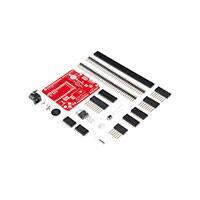
The Teensy Arduino Shield Adapter is a useful tool for upgrading existing
projects to a more powerful controller. If you have an Arduino shield you’d
love to use, but prefer working with the Teensy, then this product is just
what you need!
Materials Required
To follow along with this tutorial, we recommend you have access to the
following materials.
Teensy Arduino Shield Adapter Wishlist SparkFun Wish List
Tool Kit - Beginner
TOL-13086
This assortment of tools is great for those of you who are new to sold…
USB microB Cable - 6 Foot
CAB-10215
USB 2.0 type A to micro USB 5-pin. This is a new, smaller connector f…
Teensy 3.1
DEV-12646
The Teensy is a breadboard-friendly development board with loads of…
Suggested Reading
If you aren’t familiar with the following concepts, please review them before
�Page 2 of 11
beginning to work with the Teensy Arduino Shield Adapter.
•
•
•
•
•
•
•
Getting Started with the Teensy
Installing the Arduino IDE
How to Power Your Project
Battery Technologies
How to Solder
Working with Wire
Arduino Shields
Hardware Overview
There are several features on the Teensy Adapter Shield to be aware of.
While this shield provides basic Arduino compatibility with a standard
shield, there’s a few other fun features to check out.
Teensy Compatibility
The adapter design interfaces with all features of the Teensy 3.1, but the
adapter fits the Teensy LC footprint as well. Not all of the features available
on the adapter are compatible with the LC due to the microcontroller’s
limitations. Please check the datasheets to ensure functionality for your
project to determine the best Teensy for your use case.
Real Time Clock Battery
The battery holder included for the shield allows the users to install this into
a project and run the RTC (Real Time Clock) on the Teensy as a time
keeping option. The included coin cell battery outputs 3V and will power the
RTC in case of system power loss to maintain accurate time.
This feature does not work with the Teensy LC.
JST Power Connector
This connector breaks out the 3.3V power line from the Teensy. You can
power external devices off of this using a JST jumper wire, or you can
solder wires directly to this connection instead.
This header can also be used as a power input to both the Teensy and the
Arduino footprint and is not regulated down. The voltage supplied on the
connector must be 3.3V.
You must cut the VIN/VUSB jumper on the bottom of the Teensy if you
intend to power the Teensy via this connection and use USB for
communication/programming.
�Page 3 of 11
Barrel Jack
The barrel jack allows the user to power the Teensy and Shield combo
using a wall adapter or any power supply with a male barrel jack. This
voltage can be anywhere from 4-12V, and is regulated to 5V for powering
the Teensy. This power supply connects directly to VRAW on the Arduino
shield footprint and is not regulated down. Please read the datasheet for
any shields you intend to connect to via the adapter shield.
You must cut the VIN/VUSB jumper on the bottom of the Teensy if you
intend to power the Teensy via this connection and use USB for
communication/programming.
I2C Jumpers
The two solder jumpers included on the adapter allow the user to configure
the I2C lines on the board. The adapter ships with the jumpers closed by
default, connecting the SDA and SCL pins of the Teensy to pins A4 and
A5 on the Arduino footprint respectively. If you have an Arduino Leonardocompatible shield, you can swap this jumper to isolate the SDA and SCL
lines on the same-named pins, and access A6 and A7 of the Teensy on
A4 and A5 of the Arduino footprint. A4 and A5 of the Teensy will still
connect to the Arduino footprint SDA and SCL .
ICSP Header
The ICSP header breaks out the SPI pins for Leonardo-compatible shields.
You can also use this header to reprogram the Teensy if you have an AVR
programmer.
Additional Analog Pins
�Page 4 of 11
Just because you’re using the Teensy with an Arduino shield doesn’t mean
you want to lose the extra features of the Teensy! We’ve broken out
additional analog pins 8-11 from the Teensy to a 6-pin header, along with
AREF and GND . These pins do not interact with the Arduino shields at all,
and are simply a bonus for external sensors or inputs if desired.
DAC Pin Header
One of the other great features of the Teensy is the onboard Digital-toAnalog converter. We’ve broken this pin out to the board’s edge, along with
the PROG pin, and two corresponding GND pins.
Hardware Assembly
So you’ve got a bag of parts and are ready to get your Teensy interfaced
with your Arduino shields. It’s time to bust out that soldering iron!
We’re going to solder the adapter together in order of smallest profile to
largest. This will help make it easier to reach all the soldering points with
the iron, as well as make it easier to line all the items up properly.
Battery Holder
First, insert the battery holder and ensure it is sitting flush on the board. Flip
the adapter over, and solder the connectors. Keep in mind that the battery
clip is all metal and will conduct heat, so don’t burn yourself!
Because the battery clip will endure a lot of strain on battery insertion or
removal, you want to make sure you fully connect the pins to the board.
Make sure your solder points look nice and filled in, like this:
Capacitor
�Page 5 of 11
The next component to solder is the capacitor. The cap is polarized, so
make sure you insert it correctly into the board. The negative side of the
cap should be inserted closest to the barrel jack footprint.
Once you insert the cap, bend the legs out a bit to hold the capacitor flush
against the board while you solder it.
Once you’ve soldered the capacitor legs, clip any excess leg.
JST Connector
Next, insert the JST connector. This part tends to need a bit of a push to
insert fully into the board, so make sure you get it sitting flush before
soldering. Make sure the opening on the connector sits along the board
edge and isn’t inserted backwards.
Voltage Regulator
The voltage regulator does tend to be a bear to insert properly, so take your
time with this step. First insert the regulator legs into the board. Make sure
the regulator is inserted in the correct orientation, with the metal tab
towards the ICSP header on the board and the plastic body casing closest
to the JST connector.
�Page 6 of 11
Proper orientation of voltage regulator from the side view.
Once you’ve verified the regulator is oriented correctly, but before
soldering, bend the regulator down towards the PCB. The mounting hole on
the regulator should match up with the mounting hole on the PCB.
Solder the regulator legs and clip any excess. This part does regulate the
project voltage, so make sure to get a good solder connection on all the
pins and ensure there are no jumpers or clippings that could short the
board.
Female Headers for Teensy
At this point, you will need to determine how you want your adapter shield
to interface with your Teensy and your Arduino shields. The steps shown
are our recommended method of interfacing everything, but you can
customize this. Please check our tutorial on Getting Started with the Teensy
to see other possible configurations.
Take the female headers from your kit, and cut them down into individual
strips to fit in the Teensy footprint. Plug in the headers, and verify that they
line up well. You may also need to use one of the 6-pin female headers on
the short edge of the Teensy footprint.
�Page 7 of 11
If you have gaps between the headers like shown above, you may need to
file down the edges of the connectors to get everything to fit compactly.
Start soldering the header rows one at a time. To help keep them straight
as you solder, we recommend tacking the first and last solder points first.
Notice the first and last headers are tacked down.
This allows you to easily fix any poorly inserted or angled headers that may
occur.
These headers will never do!
If you have decided to solder all of the Teensy pins, you will also need to
solder in the inner row of headers on the shield.
Shield Headers
Next, solder on the 10-pin, 8-pin, and 6-pin headers onto the Adapter
board. To make sure you line these headers up properly, we recommend
using a pre-soldered shield as a soldering jig to hold the adapter headers in
place.
�Page 8 of 11
Pre-soldered shield used as a soldering jig to keep the headers lined up.
Keep in mind that you may need to add on the stackable headers from your
kit onto your board in order to provide enough clearance between the
Teensy and the shield you use.
Barrel Jack
The final part to solder is the barrel jack. Notice that when you insert it, the
through holes are much larger than the standard headers.
Because of the large plated through holes, you will need more solder and
heat to properly connect these and fill them in (just like on that battery clip!).
Be patient, and take it slow, to ensure you don’t burn the PCB or any
traces.
That’s it! Your adapter should now be soldered and ready to go.
All pieces inserted and soldered!
�Page 9 of 11
Teensy Adapter successfully soldered!
Teensy Headers
Now that your adapter is completed, you can use this as a soldering jig to
connect the male headers to your Teensy. Break the strip into smaller
parts, and insert them into the pre-soldered headers on the adapter. Plug
the Teensy on top, and solder away!
Crystal
Note: This step is optional and only necessary if you intend to use the
RTC feature on the Teensy 3.1.
If you intend to use the RTC on the Teensy 3.1, you will need to solder the
crystal onto the Teensy. You can solder it via the bottom or the top, but
keep in mind you should insert it where it is least likely to get knocked or
short the body of the crystal onto other components.
Double check that the crystal won’t short on any pins before soldering!
Plug it all in
�Page 10 of 11
Once everything is soldered properly, it’s time to put your boards together.
If you did not solder the Teensy directly to the adapter, plug the Teensy into
the adapter, and insert whichever shield you’ve chosen to connect.
Plug in your Teensy via USB, upload your code, and you’re good to go!
Final Adapter assembly with the Electric Imp Shield stacked on top.
Remember! If you intend to use an external power supply, you must
cut the jumper on the bottom of the Teensy to prevent shorting VUSB
and VIN.
Don’t forget to plug in your coin-cell battery, if you intend to use the RTC.
This does not work with the Teensy LC.
Programming
Because this board is simply an adapter, there is no special programming
required to start working with the adapter. You will, however, need to
program the Teensy for any Arduino shield with which you’d like to work.
When programming your Teensy, remember to select the proper board
from the Arduino IDE drop down, and select the proper serial port and baud
rate.
Please review our tutorial on Getting Started with the Teensy, for more
information on programming the Teensy in either the Arduino IDE or in a C
compiler.
Don’t forget to verify and update your pin definitions in your shield code if
you intend on using A6 or A7 in place of SDA or SCL .
Resources and Going Further
Going Further
Now that you’ve successfully got your Teensy Arduino Shield Adapter up
and running, it’s time to incorporate it into your own project!
If you have any feedback, please visit the comments or contact our
technical support team at TechSupport@sparkfun.com.
Additional Resources
Check out these additional resources for more information and other project
ideas.
• Teensy 3.1 Product Page
�Page 11 of 11
• Adapter GitHub Repository
• Teensy XBee Adapter
• RGB Panel Jumbotron
https://learn.sparkfun.com/tutorials/teensy-arduino-shield-adapter-hookup-guide?_ga=1.2... 10/23/2015
�


 工商网监
湘ICP备2023018690号
工商网监
湘ICP备2023018690号

