SATA 6Gb/s
M.2 SATA
Manual
M.2 SATA is a non-volatile, solid-state storage device delivering Serial
ATA performance, reliability and ruggedness for environmentally
challenging applications.
Manual
PSFEM5xxxGTxxx
Revision F
www.vikingtechnology.com
3/20/2017
Viking Technology
Page 1 of 48
�Revision History
Date
Revision
3/27/15
X1
5/07/15
A
5/13/15
B
7/30/15
3/1/16
C
D
9/20/16
E
3/20/17
F
Manual
PSFEM5xxxGTxxx
Revision F
www.vikingtechnology.com
Description
Initial Release from modified
PSFEM4XXXGTXXX_X3 and PN table per
PSG
Add photo, update per psg. 4/29/15
Change all PN to VPxx., remove 42/60mm
references. Change all PN to VPxx., remove
42/60mm references. Remove PFAIL/DATA
Hardening signaling. Changed Absolute max
Vin 3.6V. Reliability table changed from 72
bit per 1KB to 120 bit per 2KB page.
Changed table 4-1 Signal and Power pin 58
to Reserved for MFG_CLOCK
Revise power consumption table.
IOPS per IOmeter8. Add notes to PN table
Add 15nm PN’s
Update PN table
Revise logo and color scheme. Remove
temp sensor and SATA attribute.
Revise note 2 on Extended SMART Attribute
Actual Data table
Checked By
3/20/2017
Viking Technology
Page 2 of 48
�Legal Information
Legal Information
Copyright© 2017 Sanmina Corporation. All rights reserved. The information in
this document is proprietary and confidential to Sanmina Corporation. No part of
this document may be reproduced in any form or by any means or used to make
any derivative work (such as translation, transformation, or adaptation) without
written permission from Sanmina. Sanmina reserves the right to revise this
documentation and to make changes in content from time to time without
obligation on the part of Sanmina to provide notification of such revision or
change.
Sanmina provides this documentation without warranty, term or condition of any
kind, either expressed or implied, including, but not limited to, expressed and
implied warranties of merchantability, fitness for a particular purpose, and noninfringement. While the information contained herein is believed to be accurate,
such information is preliminary, and should not be relied upon for accuracy or
completeness, and no representations or warranties of accuracy or
completeness are made. In no event will Sanmina be liable for damages arising
directly or indirectly from any use of or reliance upon the information contained in
this document. Sanmina may make improvements or changes in the product(s)
and/or the program(s) described in this documentation at any time.
Sanmina, Viking Technology, Viking Modular Solutions, and Element logo are
trademarks of Sanmina Corporation. Other company, product or service names
mentioned herein may be trademarks or service marks of their respective
owners.
Manual
PSFEM5xxxGTxxx
Revision F
www.vikingtechnology.com
3/20/2017
Viking Technology
Page 3 of 48
�Ordering Information: M.2 80mm SATA SSD Solid-State Drive
Part Number
Interface
VPFEM5480GTCZMTK
VPFEM5480GTCZMMC
VPFEM5240GTCVMTK
VPFEM5240GTCAMMC
VPFEM5120GTCTMTK
VPFEM5120GTCBMMC
VPFEM5480GTCZMTL
VPFEM5240GTCAMTL
VPFEM5120GTCBMTL
SATA 6GB
SATA 6GB
SATA 6GB
SATA 6GB
SATA 6GB
SATA 6GB
SATA 6GB
SATA 6GB
SATA 6GB
User
Capacity
(GB)
480
480
240
240
120
120
480
240
120
NAND
Temperature
(C)
MLC
MLC
MLC
MLC
MLC
MLC
MLC
MLC
MLC
(0 to +70'c)
(0 to +70'c)
(0 to +70'c)
(0 to +70'c)
(0 to +70'c)
(0 to +70'c)
(0 to +70'c)
(0 to +70'c)
(0 to +70'c)
NAND
TSB A19nm K-die
Micron 16nm L95B
TSB A19nm K-die
Micron 16nm L95B
TSB A19nm K-die
Micron 16nm L95B
TSB 15nm L-die
TSB 15nm L-die
TSB 15nm L-die
Notes:
1. Usable capacity based on a level of over-provisioning applied to wear leveling, bad sectors, index tables etc.
2. Higher capacity points may be available based on customer application. Consult your local Viking FAE Engineer.
3. SSD’s ship unformatted from the factory unless otherwise requested.
4. 1 GB = 1,000,000,000 Byte
5. One Sector = 512 Byte.
.
Manual
PSFEM5xxxGTxxx
Revision F
www.vikingtechnology.com
3/20/2017
Viking Technology
Page 4 of 48
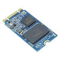
�Product Picture(s)
M.2 2280 FRONT
Manual
PSFEM5xxxGTxxx
Revision F
www.vikingtechnology.com
M.2 2280 BACK
3/20/2017
Viking Technology
Page 5 of 48
�Enterprise SSD – An Enterprise SSD contains hardware and firmware that
detect and manage power failures. This allows the drive to flush the controller
cache and harden data to NAND flash. No data is lost or corrupted.
.
Manual
PSFEM5xxxGTxxx
Revision F
www.vikingtechnology.com
3/20/2017
Viking Technology
Page 6 of 48
�Table of Contents
1
INTRODUCTION
10
1.1
Features
10
1.2
Block Diagram
11
1.3
SATA Interface
12
2
2.1
PRODUCT SPECIFICATIONS
Performance
13
13
2.2
Timing
2.2.1 STANDBY IMMEDIATE Command
13
13
2.3
Electrical Characteristics
2.3.1 Absolute Maximum Ratings
2.3.2 Supply Voltage
2.3.3 Power Consumption
14
14
14
15
2.4
Environmental Conditions
2.4.1 Temperature and Altitude
2.4.2 Shock and Vibration
2.4.3 Electromagnetic Immunity
15
15
16
16
2.5
16
Reliability
2.6
Data Security
2.6.1 Encryption
2.6.2 Quick Erase
2.6.3 Military Secure Erase / Sanitization/ Purge Routines
16
16
17
18
3
29
MECHANICAL INFORMATION
3.1
Dimensions
29
3.2
Card Edge Detail
31
3.3
M.2 SSD Weight
33
4
PIN AND SIGNAL DESCRIPTIONS
Manual
PSFEM5xxxGTxxx
Revision F
www.vikingtechnology.com
33
3/20/2017
Viking Technology
Page 7 of 48
�4.1
Signal and Power Description Tables
33
4.2
Hot Plug Support
34
5
COMMAND SETS
34
5.1
ATA Commands
5.1.1 48-Bit Address Command Set
5.1.2 ATA General Feature Command Set
5.1.3 Device Configuration Overlay Command Set
5.1.4 General Purpose Log Command Set
5.1.5 Host Protected Area Command Set
5.1.6 Power Management Command Set
5.1.7 Security Mode Feature Set
5.1.8 Identify Device Data
5.1.1 S.M.A.R.T. Support
5.1.2 SATA 3.0 S.M.A.R.T. Command Set
34
35
36
36
36
36
37
37
38
42
43
5.2
SATA Commands
5.2.1 Native Command Queuing (NCQ)
47
47
6
REFERENCES
47
7
GLOSSARY
48
Manual
PSFEM5xxxGTxxx
Revision F
www.vikingtechnology.com
3/20/2017
Viking Technology
Page 8 of 48
�Table of Tables
Table 2-1: Maximum Sustained Read and Write Bandwidth ____________________________ 13
Table 2-2: Random Read and Write Input/Output Operations per Second (IOPS) ___________ 13
Table 2-3: Timing Specifications _________________________________________________ 13
Table 2-4: STANDBY IMMEDIATE Timing _________________________________________ 14
Table 2-5: Absolute Maximum Ratings ____________________________________________ 14
Table 2-6: Operating Voltage ____________________________________________________ 14
Table 2-7: Typical Power Consumption at 3.3V ______________________________________ 15
Table 2-8: Temperature and Altitude Related Specifications ____________________________ 15
Table 2-9: Shock and Vibration Specifications _______________________________________ 16
Table 2-10: Reliability Specifications ______________________________________________ 16
Table 2-11: Military Secure Erase / Sanitize Routines _________________________________ 18
Table 3-1: M.2 SSD weight ______________________________________________________ 33
Table 4-1: M.2 SATA Connector Pinouts ___________________________________________ 33
Table 5-1: Supported ATA Commands ____________________________________________ 34
Table 5-2: List of Device Identification _____________________________________________ 38
Table 5-3: S.M.A.R.T. Command Set ______________________________________________ 43
Table 5-4: Extended SMART Attribute Table ________________________________________ 43
Table 5-5: Extended SMART Attribute Actual Data ___________________________________ 44
Table 5-6: Supported S.M.A.R.T. EXECUTE OFF-LINE IMMEDIATE Subcommands ________ 47
Table of Figures
Figure 1-1: High-Level Block Diagram _____________________________________________ 11
Figure 3-1: Dimensions ________________________________________________________ 29
Figure 3-2: Dimension Details for M.2 80mm length __________________________________ 30
Figure 3-3: Dimension Details for M.2 card edge _____________________________________ 31
Figure 3-4: Dimension Details for M.2 connector and notch ____________________________ 32
Manual
PSFEM5xxxGTxxx
Revision F
www.vikingtechnology.com
3/20/2017
Viking Technology
Page 9 of 48
�1 Introduction
Viking’s rugged industrial designed SSD’s offer the highest flash storage
reliability and performance in harsh environments such as shock, vibration,
humidity, altitude, ESD, and extreme temperatures.
1.1 Features
The SSD delivers the following features:
Seamless SATA Revision 3.2 interface support for SATA up to 6Gb/s
Low overall SSD power consumption
Supports Native Command Queuing (NCQ) to 32 commands
Compatible with all major SLC and MLC flash technologies
S.M.A.R.T.
Superior static and dynamic wear-leveling algorithm
Efficient error recovery
Power hold-up circuit technology ensures no data loss resulting from an
unexpected power loss and is supported for industrial temperatures
TRIM Support
48-bit LBA Support
Manual
PSFEM5xxxGTxxx
Revision F
www.vikingtechnology.com
3/20/2017
Viking Technology
Page 10 of 48
�1.2 Block Diagram
Figure 1-1: High-Level Block Diagram
3.3V
Notes: Support for up to 8-channels and 32 CE in the NAND Flash interface
Manual
PSFEM5xxxGTxxx
Revision F
www.vikingtechnology.com
3/20/2017
Viking Technology
Page 11 of 48
�1.3 SATA Interface
The Serial ATA (SATA) interface is compliant with the SATA IO Serial
ATA specification, revision 3.0 that supports SATA up to 6 Gbps.
The SATA interface connects the host computer to the SSD subsystem.
The SATA interface runs at a maximum speed of 6 Gbps (Giga-bits per
second). If the host computer is unable to negotiate a speed of 6 Gbps,
the SATA interface automatically renegotiates to a speed of 3 Gbps or 1.5
Gbps.
For a list of supported commands and other specifics, please see Chapter 5.
Manual
PSFEM5xxxGTxxx
Revision F
www.vikingtechnology.com
3/20/2017
Viking Technology
Page 12 of 48
�2 Product Specifications
2.1 Performance
Table 2-1: Maximum Sustained Read and Write Bandwidth
Access Type
Sequential Read, 256K
Sequential Write, 256K
MB/s
Up to 550
Up to 530
Notes:
1. Performance measured using Iometer 08
2. Performance may vary from flash configuration, SDR configuration, and platform.
3. Refer to Application Note AN0006 for Viking SSD Benchmarking Methodology.
4. Data is based on SSD’s using Toshiba A19nm Toggle NAND devices
Table 2-2: Random Read and Write Input/Output Operations per Second
(IOPS)
Access Type
Read, 4K
Write, 4K
IOPS
Up to 100,000
Up to 90,000
Notes:
1. Performance measured using Iometer 08 with queue depth set to 32.
2. Write Cache enabled with DDR cache.
3. Random IOPS cover the entire range of legal logical block addresses (LBA’s). Measurements are
performed on a full drive (all LBA’s have valid content).
4. Performance may vary by NAND type and host.
5. Refer to Application Note AN0006 for Viking SSD Benchmarking Methodology.
6. Data is based on SSD’s using Toshiba A19nm NAND devices
2.2 Timing
Table 2-3: Timing Specifications
Type
Average Latency
Read (at 64KB)
0.14mS
Write (at 64KB)
2.12mS
Power On Ready (POR)
436mS
Notes:
1. Device measured using Drivemaster.
2. DRQ (Data Transfer Requested) bit being asserted
2.2.1 STANDBY IMMEDIATE Command
The Power-On-to-Ready time assumes a proper shutdown (power removal
preceded by STANDBY IMMEDIATE command. A STANDBY IMMEDIATE
before power down always performs a graceful shutdown and does not require
the use of the hold-up circuit.
Manual
PSFEM5xxxGTxxx
Revision F
www.vikingtechnology.com
3/20/2017
Viking Technology
Page 13 of 48
�Table 2-4: STANDBY IMMEDIATE Timing
Power Cycle Endurance
STANDBY IMMEDIATE to WE completed
Min
-
Max
72.9
Unit
ms
Notes:
1. From Standby Immediate command to NAND Write Protect enable.
2.3 Electrical Characteristics
2.3.1 Absolute Maximum Ratings
Values shown are stress ratings only. Functional operation outside normal
operating values is not implied. Extended exposure to absolute maximum ratings
may affect reliability.
Table 2-5: Absolute Maximum Ratings
Description
Maximum Voltage Range for Vin
Maximum Temperature Range
Min
-0.2
-40
Max
3.6
85
Unit
V
c
Min
3.135
Max
3.465
Unit
V
2.3.2 Supply Voltage
The operating voltage is 3.3V
Table 2-6: Operating Voltage
Description
Operating Voltage for 3.3 V (+/- 5%)
Manual
PSFEM5xxxGTxxx
Revision F
www.vikingtechnology.com
3/20/2017
Viking Technology
Page 14 of 48
�2.3.3 Power Consumption
All onboard power requirements of the SSD are derived from the SATA 3.3V rail.
Table 2-7: Typical Power Consumption at 3.3V
Capacity
Flash: TSBA19
Read()
Write
128GB
8GBx1Diex16CE
2.224
3.446
256GB
8GBx1Diex32CE
2.21
512GB
8GBx2Diex32CE
1TB
16GBx2Diex32CE
Capacity
Flash: M L95B
128GB
Idle
Partial
Slumber
0.505
0.0911
0.0911
4.31
0.566
0.0695
0.068
2.335
4.431
0.632
0.0824
0.0798
2.481
4.234
0.651
0.1014
0.1009
Read()
Write
Idle
Partial
Slumber
16GBx1Diex8CE
2.193
2.524
0.625
0.1158
0.0716
256GB
16GBx1Diex16CE
2.161
3,624
0,571
0.0675
0,0659
512GB
16GBx2Diex16CE
2.39
3.971
0.567
0.1199
0.0968
Notes:
1. The average value of power consumption is achieved based on 100% conversion efficiency.
2. The measured power voltage is 5V.
3. Samples were built of Toshiba A19nm Toggle MLC NAND flash and measured under ambient
temperature.
4. Sequential R/W is measured while testing 400MB sequential R/W 5 times by CrystalDiskMark.
5. Power Consumption may differ according to flash configuration and platform.
2.4 Environmental Conditions
2.4.1 Temperature and Altitude
Table 2-8: Temperature and Altitude Related Specifications
Conditions
Commercial
Temperature- Ambient
Industrial
Temperature- Ambient
Humidity (noncondensing)
Manual
PSFEM5xxxGTxxx
Revision F
www.vikingtechnology.com
Operating
0 to 70°C
Shipping
-40 to 85°C
Storage
-40 to 85°C
-40 to 85°C
-40 to 85°C
-40 to 85°C
90% under 40C
93% under 40C
93% under 40C
3/20/2017
Viking Technology
Page 15 of 48
�2.4.2 Shock and Vibration
SSD products are tested in accordance with environmental specification for
shock and vibration
Table 2-9: Shock and Vibration Specifications
Stimulus
Shock
Description
500G, 2ms
20 – 80 Hz/1.52mm
80 – 2000 Hz/20G
(X,Y,Z axis / 30 min for each)
Vibration
2.4.3 Electromagnetic Immunity
M.2 is an embedded product for host systems and is designed not to impair with
system functionality or hinder system EMI/FCC compliance.
2.5 Reliability
Table 2-10: Reliability Specifications
Parameter
Description
ECC
120 bit per 2KB page
Read
Endurance
Write
Endurance
Unlimited
32GB
64GB
128GB
256GB
512GB
1024GB
79 TBW
158 TBW
317 TBW
635 TBW
1272 TBW
2548 TBW
Data retention
> 90 days at NAND expiration
2.6 Data Security
2.6.1 Encryption
The SSD drive is a self-encrypting drive (SED), with a bulk data encryption
feature that provides automatic hardware-based data security and enhanced
secure erase capability.
A self-encrypting drives, scrambles data using a data encryption key as it is
written to the drive and then descrambles it with the key as it is retrieved. This
gives the user the highest level of data protection available and provides a fast
Manual
PSFEM5xxxGTxxx
Revision F
www.vikingtechnology.com
3/20/2017
Viking Technology
Page 16 of 48
�erase simply by deleting the encryption key, eliminating the need for time
consuming data-overwrite. Data on the drive is instantly rendered unreadable.
The SSD supports AES-256 encryption and ATA Secure Erase features to
protect sensitive data.
The SSD drives support the following security features:
AES 256 on the fly support.
RSA 512/1024/2048
SHA 160/256/512
TCG OPAL SSC V1.0
2.6.2 Quick Erase
Quick Erase has been designed to remove data under prompt and urgent
situation and is triggered by sending an ATA Command.
Input Info of Executing Quick Erase Command
Normal Output Info of Executing Quick Erase Command
Manual
PSFEM5xxxGTxxx
Revision F
www.vikingtechnology.com
3/20/2017
Viking Technology
Page 17 of 48
�Device/Head Register:
DEV shall indicate the selected device.
Status Register:
BSY shall be cleared to zero indicating command completion.
DRDY shall be set to one.
DF (Device Fault) shall be cleared to zero.
DRQ shall be cleared to zero.
ERR shall be cleared to zero.
2.6.3 Military Secure Erase / Sanitization/ Purge Routines
Many government and military organizations such as NIST/NSA define their own
standard and procedures for performing a Military Secure Erase which overwrite
different patterns to sanitize the flash media. Some of the more common military
or government purge routines are defined in the following table and the data
security features of the drive comply with Department of Defense (DoD) and US
military data security standards.
Table 2-11: Military Secure Erase / Sanitize Routines
Standard
Action
SSD
1
Code
NSA/CSS 9-12
Erase and overwrite all locations with a known unclassified
pattern. Verify the overwrite procedure by randomly
rereading the overwritten information to confirm that only
the known pattern can be recovered.
Note 1
NSA/CSS 130-2
Erase the media and overwrite with random data 2 times,
then erase and overwrite with a character
Note 1
DoD5220.22-M
Erase the media and overwrite with single character, then
erase again
Note 1
NISPOMSUP
Chap 8, Sect.8-501
Erase the media and overwrite with single character, then
erase again and overwrite with single character, then
erase again and overwrite with random character then
erase again
Note 1
USA Army 380-19
Erase the media and overwrite with random data, erase
and overwrite with a character, then erase and overwrite
with complement of the character
Note 1
Navy NAVSO P-523926
Erase the media and overwrite with random data, then
erase again
Note 1
Air Force AFSSI 5020
Erase the media and overwrite with pattern, repeat 3 times
Note 1
Air Force AFSSI 8580
TBD
Note 1
Notes:
1. Enabled using ATA commands
Manual
PSFEM5xxxGTxxx
Revision F
www.vikingtechnology.com
3/20/2017
Viking Technology
Page 18 of 48
�Manual
PSFEM5xxxGTxxx
Revision F
www.vikingtechnology.com
3/20/2017
Viking Technology
Page 19 of 48
�2.6.3.1 AFSSI 5020
Pattern:
1) To erase the whole disk.
2) To fill the whole disk with random data.
Input Info of Executing AFSSI 5020 Command
Normal Output Info of Executing AFSSI 5020 Command
Device/Head Register:
DEV shall indicate the selected device.
Status Register:
BSY shall be cleared to zero indicating command completion.
DRDY shall be set to one.
DF (Device Fault) shall be cleared to zero.
DRQ shall be cleared to zero.
ERR shall be cleared to zero.
Manual
PSFEM5xxxGTxxx
Revision F
www.vikingtechnology.com
3/20/2017
Viking Technology
Page 20 of 48
�2.6.3.2 DOD 5220.22-M
Pattern:
1) To fill the whole disk with fixed character pattern of 0x55.
2) To erase the whole disk.
Input Info of Executing DoD 5220.22-M Command
Normal Output Info of Executing DoD 5220.22-M Command
Device/Head Register:
DEV shall indicate the selected device.
Status Register:
BSY shall be cleared to zero indicating command completion.
DRDY shall be set to one.
DF (Device Fault) shall be cleared to zero.
DRQ shall be cleared to zero.
ERR shall be cleared to zero.
Manual
PSFEM5xxxGTxxx
Revision F
www.vikingtechnology.com
3/20/2017
Viking Technology
Page 21 of 48
�2.6.3.3 USA NAVY NAVSO P-5239-26
Pattern:
1) To erase the whole disk.
2) To fill the whole disk with random data.
3) To erase the whole disk again.
Input Info of Executing USA Navy NAVSO P-5239-26 Command
Normal Output Info of Executing USA Navy NAVSO P-5239-26 Command
Device/Head Register:
DEV shall indicate the selected device.
Status Register:
BSY shall be cleared to zero indicating command completion.
DRDY shall be set to one.
DF (Device Fault) shall be cleared to zero.
DRQ shall be cleared to zero.
ERR shall be cleared to zero.
Manual
PSFEM5xxxGTxxx
Revision F
www.vikingtechnology.com
3/20/2017
Viking Technology
Page 22 of 48
�2.6.3.4 NSAMANUAL 130-2
Pattern:
1) To erase the whole disk.
2) To fill the whole disk with random data.
3) To fill the whole disk with random data one more time.
4) To erase the whole disk again.
5) To fill the whole disk with fixed character pattern of 0x55.
Input Info of Executing NSA Manual 130-2 Command
Normal Output Info of Executing NSA Manual 130-2 Command
Device/Head Register:
DEV shall indicate the selected device.
Status Register:
BSY shall be cleared to zero indicating command completion.
DRDY shall be set to one.
DF (Device Fault) shall be cleared to zero.
DRQ shall be cleared to zero.
Manual
PSFEM5xxxGTxxx
Revision F
www.vikingtechnology.com
3/20/2017
Viking Technology
Page 23 of 48
�ERR shall be cleared to zero.
Manual
PSFEM5xxxGTxxx
Revision F
www.vikingtechnology.com
3/20/2017
Viking Technology
Page 24 of 48
�2.6.3.5 USA-ARMY 380-19
Pattern:
1) To erase the whole disk.
2) To fill the whole disk with random data.
3) To fill the whole disk with fixed character pattern of 0x55.
4) To fill the whole disk with fixed character pattern of 0xAA.
Input Info of Executing USA-Army 380-19 Command
Normal Output Info of Executing USA-Army 380-19 Command
Device/Head Register:
DEV shall indicate the selected device.
Status Register:
BSY shall be cleared to zero indicating command completion.
DRDY shall be set to one.
DF (Device Fault) shall be cleared to zero.
DRQ shall be cleared to zero.
ERR shall be cleared to zero.
Manual
PSFEM5xxxGTxxx
Revision F
www.vikingtechnology.com
3/20/2017
Viking Technology
Page 25 of 48
�2.6.3.6 NISPOMSUP CHAP 8, SECT. 8-501
Pattern:
1) To fill the whole disk with fixed character pattern of 0x55.
2) To fill the whole disk with fixed character pattern of 0xAA.
3) To fill the whole disk with random data.
Input Info of Executing NISPOMSUP chap 8, Sect. 8-501 Command
Normal Output Info of Executing NISPOMSUP chap 8, Sect. 8-501 Command
Device/Head Register:
DEV shall indicate the selected device.
Status Register:
BSY shall be cleared to zero indicating command completion.
DRDY shall be set to one.
DF (Device Fault) shall be cleared to zero.
DRQ shall be cleared to zero.
ERR shall be cleared to zero.
Manual
PSFEM5xxxGTxxx
Revision F
www.vikingtechnology.com
3/20/2017
Viking Technology
Page 26 of 48
�2.6.3.7 NSA/CSS 9-12
Pattern:
1) To fill the whole disk with fixed character pattern of 0x55.
Input Info of Executing NSA/CSS 9-12 Command
Normal Output Info of Executing NSA/CSS 9-12 Command
Device/Head Register:
DEV shall indicate the selected device.
Status Register:
BSY shall be cleared to zero indicating command completion.
DRDY shall be set to one.
DF (Device Fault) shall be cleared to zero.
DRQ shall be cleared to zero.
ERR shall be cleared to zero.
Manual
PSFEM5xxxGTxxx
Revision F
www.vikingtechnology.com
3/20/2017
Viking Technology
Page 27 of 48
�2.6.3.8 AFSSI 8580
Pattern:
1) To fill the whole disk with fixed character pattern of 0x55.
2) To fill the whole disk with fixed character pattern of 0xAA.
3) To fill the whole disk with random data.
Input Info of Executing AFSSI 8580 Command
Normal Output Info of Executing AFSSI 8580 Command
Device/Head Register:
DEV shall indicate the selected device.
Status Register:
BSY shall be cleared to zero indicating command completion.
DRDY shall be set to one.
DF (Device Fault) shall be cleared to zero.
DRQ shall be cleared to zero.
ERR shall be cleared to zero.
Manual
PSFEM5xxxGTxxx
Revision F
www.vikingtechnology.com
3/20/2017
Viking Technology
Page 28 of 48
�3 Mechanical Information
3.1 Dimensions
Figure 3-1: Dimensions
d
VRFEM6xxx
Note2
VRFEM4xxx
Note2
VPFEM5xxx
Note2
Notes:
1. All dimensions are in millimeter. General tolerance is ± 0.15. PCB thickness 0.8 ± 0.08
2. Refer to Ordering Information table for the complete Viking part number that describes the “xxx”.
Manual
PSFEM5xxxGTxxx
Revision F
www.vikingtechnology.com
3/20/2017
Viking Technology
Page 29 of 48
�Figure 3-2: Dimension Details for M.2 80mm length
VPFEM5xxx
Note2
FOR CARD EDGE DETAIL
SEE SECTION 3.2
Notes:
1. All dimensions are in millimeter. General tolerance is ± 0.15. PCB thickness 0.8 ± 0.08
2. Refer to Ordering Information table for the complete Viking part number that describes the “xxx”.
Manual
PSFEM5xxxGTxxx
Revision F
www.vikingtechnology.com
3/20/2017
Viking Technology
Page 30 of 48
�3.2 Card Edge Detail
Figure 3-3: Dimension Details for M.2 card edge
Manual
PSFEM5xxxGTxxx
Revision F
www.vikingtechnology.com
3/20/2017
Viking Technology
Page 31 of 48
�Figure 3-4: Dimension Details for M.2 connector and notch
Key notch detail
Manual
PSFEM5xxxGTxxx
Revision F
www.vikingtechnology.com
3/20/2017
Viking Technology
Page 32 of 48
�3.3 M.2 SSD Weight
Table 3-1: M.2 SSD weight
Length
80 mm
Weight


 工商网监
湘ICP备2023018690号
工商网监
湘ICP备2023018690号
