78-5102-0126-8 B
Product Data Sheet
3M™ Active Optical
Cable (AOC) Assemblies
for CX4 and QSFP+
Applications
3M Electronic Solutions Division
6801 River Place Blvd.
Austin, TX 78726-9000
www.3Mconnectors.com
�Document Number: 78-5102-0126-8 B
Title: Product Data Sheet
Subject: 3M™ Active Optical Cable (AOC) Assemblies for CX4 and QSFP+
Issue Date: August 10, 2012
Supersedes: Rev A
Page:
1 of 9
Applications
Table of Contents
1.0
DESCRIPTION..................................................................................................................................................2
2.0
AOC BLOCK DIAGRAM .................................................................................................................................2
3.0
CONNECTOR PIN ASSIGNMENT .................................................................................................................3
3.1
Type Sense (TSense) ..............................................................................................................................3
3.2
Output Disable (ODIS) ...........................................................................................................................3
3.3
Fault ........................................................................................................................................................4
4.0
LED INDICATIOR SUMMARY ......................................................................................................................4
5.0
ABSOLUTE MAXIMUM RATING .................................................................................................................4
6.0
RECOMMENDED OPERATING CONDITIONS............................................................................................4
7.0
8.0
9.0
6.1
Type Sense (TSense) ..............................................................................................................................4
6.2
Output Disable (ODIS) ...........................................................................................................................4
6.3
Fault ........................................................................................................................................................4
EQUIPMENT CHARACTERISTICS................................................................................................................5
7.1
Transmitter and Receiver Electrical Characteristics ...............................................................................5
7.2
Optical Characteristics ............................................................................................................................5
7.3
Link Performance....................................................................................................................................5
TESTING...........................................................................................................................................................6
8.1
Standards and Regulatory Documents ....................................................................................................6
8.2
Functional Performance Criteria .............................................................................................................6
8.3
Mechanical Dimensions..........................................................................................................................7
ORDERING INFORMATION ..........................................................................................................................8
3M Electronic Solutions Division
6801 River Place Blvd.
Austin, TX 78726-9000
www.3Mconnectors.com
© 3M 2012. All Rights Reserved.
�Document Number: 78-5102-0126-8 B
Title: Product Data Sheet
Subject: 3M™ Active Optical Cable (AOC) Assemblies for CX4 and QSFP+
Issue Date: August 10, 2012
Supersedes: Rev B
Page:
2 of 9
Applications
1.0
Description
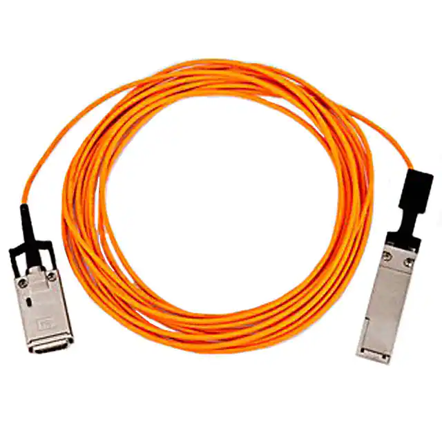
3M’s new CX4-QSFP+ hybrid active optical cable assembly provides up to 5 Gbps per channel transmission over
100 meters of multimode fiber for high-performance computing and other ultra high-throughput networking
environments. The AOC transmits four parallel channels each operating up to 5Gbps. Using industry leading Vcsel
technology and an advanced new light-engine design, the 3M AOC provides exceptional cost/performance value.
Features
• Low-power
• Four channels each operating up to 5Gbps
• Fiber link up to 100m
• Reliable 850nm Vcsel technology
• 0 to +70 degree Celsius operating temperature range
• Hot pluggable
• Bend insensitive fiber
2.0
AOC block diagram
This document summarizes the product performance specifications for the 3M Active Optical Cable Assembly for
CX4 Applications. In the event of performance data conflicts between this specification and any document listed
below, this specification supersedes those documents.
3M Electronic Solutions Division
6801 River Place Blvd.
Austin, TX 78726-9000
www.3Mconnectors.com
© 3M 2012. All Rights Reserved.
�Document Number: 78-5102-0126-8 B
Title: Product Data Sheet
Subject: 3M™ Active Optical Cable (AOC) Assemblies for CX4 and QSFP+
Issue Date: August 10, 2012
Supersedes: Rev B
Page:
3 of 9
Applications
3.0
Connector Pin Assignment
In an active optical version of the CX4-QSFP+ cable assembly, certain ground pins are repurposed to provide power
and other control signaling. A CX4-QSFP+ hybrid active optical module requires a 3.3Volt power supply at each
end. On the CX4 side, this voltage supply is provided through pin G8 which is normally a ground pin in an
equivalent copper cable. It is used to provide electrical power to the opto-electronics inside the module. The host
uses G7, Type_Sense (labeled ‘TSense’ in the diagram below), to detect whether the module is an active of passive
variety. If the host detects a ground it automatically assumes the module is passive variety and thus requires no
electrical power. The 5K-Ohm resister allows the host to develop the appropriate voltage across a voltage
comparator circuit to detect that the module is active version and then automatically supplies power to pin G8.
3.1
Type Sense (TSense)
The Type_Sense pin on the module connector is an input pin. It is connected to a 5K-Ohm resister connected to
ground. The host system uses this line to detect whether this is an active optical module and thus provides power via
the voltage input pin G8.
3.2
Output Disable (ODIS)
The ODIS line is an input line to the module; it is used by the host system to switch OFF all the lasers. To turn ON
all the lasers the ODIS line must be kept low by the host system. The lasers turn OFF as soon as the ODIS line is
taken high. The module provides an internal 5K-Ohm pull-up resister to Vcc_In.
3M Electronic Solutions Division
6801 River Place Blvd.
Austin, TX 78726-9000
www.3Mconnectors.com
© 3M 2012. All Rights Reserved.
�Document Number: 78-5102-0126-8 B
Title: Product Data Sheet
Subject: 3M™ Active Optical Cable (AOC) Assemblies for CX4 and QSFP+
Issue Date: August 10, 2012
Supersedes: Rev B
Page:
4 of 9
Applications
3.3
Fault
In normal operation, the CX4 module is able to respond to various fault conditions and signal them via the LEDS
and the Fault line on the CX4 connector. The following conditions are recognized:
• RX loss-of-signal. If the Receiver IC detects loss-of-signal on one or more channels then the module will
turn ON the Red LED and pull the fault line low to ground. When the fault is cleared, the Red LED will
turn OFF and the fault line will be pulled low to ground.
• TX fault: If the transmitter detects a transmit fault (laser short or open circuit) it will alternately flashes the
Red and Green LEDs and pulls the fault line low. The module must then be power cycled to continue.
Note: If no fault has occurred then the module will release the Fault line (open-collector output). The host
system is required to supply the recommended 5K-Ohm pull-up resister to this output line.
4.0
LED Indicator Summary
Green LED
5.0
Red LED
Fault line
off
off
low
on
on
off
on
low
Open-collector
flashing
flashing
Open-collector
Description
Power has not been applied or module is starting up and has not yet
initialized.
Module is operating normally.
Receiver has detected loss of signal on one of more channels
Alternate flashing of Red and Green LEDs means a laser short or
open circuit has been detected.
Absolute Maximum Rating
Parameters
Min
Storage temperature
Relative humidity
Supply voltage
Operating case temperature
-40
5
3.10
0
Typ
Max
Units
+80
85
3.65
+70
Deg. Celsius
%
V
Deg. Celsius
Note: if product is exposed to conditions beyond the levels indicated, the reliability of the product is likely to
be negatively affected.
6.0
Recommended Operating Conditions
Parameter
Min
Typ
Max
Units
Supply voltage, Vcc
Power dissipation
Operating case temperature
3.15
3.3
730
3.57
V
mW
Deg. Celsius
Differential impedance input/output
Transmitter differential input voltage
Receiver differential output voltage. peak-to-peak
Differential input and output impedance
Signaling rate/channel, NRZ
3M Electronic Solutions Division
6801 River Place Blvd.
Austin, TX 78726-9000
www.3Mconnectors.com
0
+70
100
120
1200
317
100
5.00
Ohm
mV
mV
Ohm
Gbps
© 3M 2012. All Rights Reserved.
�Document Number: 78-5102-0126-8 B
Title: Product Data Sheet
Subject: 3M™ Active Optical Cable (AOC) Assemblies for CX4 and QSFP+
Issue Date: August 10, 2012
Supersedes: Rev B
Page:
5 of 9
Applications
7.0
Equipment Characteristics
7.1
Transmitter and Receiver Electrical Characteristics
Parameters
Min
Transmitter differential input voltage, peak-to-peak
Receiver differential output voltage, peak-to-peak
Peak-to-peak jitter at receiver output
Receiver rise time, 20 -80%
Link bit error rate (BER)
120
7.2
Typ
Units
1200
mV
mV
ps
ps
Bit
317
36
75
700Mhz.Km and
effective modal bandwidth of >950MHz.km at wavelength of 850nm. This allows excellent link performance up to
100 meter for InfiniBand SDR and DDR rates.
3M Electronic Solutions Division
6801 River Place Blvd.
Austin, TX 78726-9000
www.3Mconnectors.com
© 3M 2012. All Rights Reserved.
�Document Number: 78-5102-0126-8 B
Title: Product Data Sheet
Subject: 3M™ Active Optical Cable (AOC) Assemblies for CX4 and QSFP+
Issue Date: August 10, 2012
Supersedes: Rev B
Page:
6 of 9
Applications
8.0
Testing
8.1
Standards and Regulatory Documents
The CX4-QSFP+ AOC has been designed and tested in accordance with the following specifications, reliability and
regulatory requirements:
• Optical interface conforms to InfiniBand Architecture Specification Volume 2, Release 1.2.1
• Product tested according to Telcordia GR-468-CORE Generic Reliability Assurance Requirements for
Optoelectronics Devices
• Compliant to Restriction on Hazardous Substances (RoHS) per EU requirements (ROHS directive
2002/95/EC)
• Class 1M Eye safe per IEC 60825-1/CDRH
• Conforms to UL 94 –V0 rating
• Meets FCC Class B and CE Emissions and Immunity requirements
• EN61000-4-2 (15KV air discharge during operation, and 8KV direct contact discharges to the case),
Human Body Model per JEDEC JESD22-A114-B, Human Body Model JEDEC JESD22-A114-B
8.2
Functional Performance Criteria
The product was tested in accordance with various EIA and MIL-STDs as specified below. Sample sizes were
selected in accordance with individual test criteria. Unless otherwise specified, all values and limits are typical of
those obtained by qualification testing of the subject product.
1
2
3
4
5
6a
6b
7a
7b
7c
8a
9a
9b
9c
9d
10
Test
Reference
Results
High Temperature Operating Life
Biased Damp Heat
Temperature Cycling
Biased Cyclic Moisture Resistance
Thermal Shock
Mechanical Shock (MS)
Mechanical Vibration (MV)
ESD - HBM
ESD air discharge
ESD Contact discharge
Durability
Insertion Force
Withdrawal Force
Retention Force
Off-axis load capability
Impact test
Section 5.18 (GR-468-CORE)
MIL-STD-202 Method 103
MIL-STD-883 Method 1010
MIL-STD-883 Method 1004
MIL-STD-883 Method 1011.9
MIL-STD-883 Method 2002B
MIL-STD-883 Method 2007
JESD22-A114-B
EN61000-4-2
EN61000-4-2
EIA-364-09C
EIA/ECA-36413D
EIA/ECA-36413D
TIA-455-6-B, FOTP 6
EIA-364-38B
TIA-455-2C, FOTP-2
Pass
Pass
Pass
Pass
Pass
Pass
Pass
Pass
Pass
Pass
Pass
Pass
Pass
Pass
Pass
Pass
3M Electronic Solutions Division
6801 River Place Blvd.
Austin, TX 78726-9000
www.3Mconnectors.com
© 3M 2012. All Rights Reserved.
�Document Number: 78-5102-0126-8 B
Title: Product Data Sheet
Subject: 3M™ Active Optical Cable (AOC) Assemblies for CX4 and QSFP+
Issue Date: August 10, 2012
Supersedes: Rev B
Page:
7 of 9
Applications
8.3
Mechanical Dimensions
CX4 Interface:
QSFP+ Interface:
3M Electronic Solutions Division
6801 River Place Blvd.
Austin, TX 78726-9000
www.3Mconnectors.com
© 3M 2012. All Rights Reserved.
�Document Number: 78-5102-0126-8 B
Title: Product Data Sheet
Subject: 3M™ Active Optical Cable (AOC) Assemblies for CX4 and QSFP+
Issue Date: August 10, 2012
Supersedes: Rev B
Page:
8 of 9
Applications
9.0
Ordering Information
6A24-B04X1-XXX.0-0
|
|__Standard lengths:
|
1m increments from 2m to 30m,35m,40m,45m,50m,60m,70m,80m ,90m,100m
|
|______Cable Type:
2=Plenum
4=Low Smoke Zero Halogen (LSZH)
Refer to 3M Drawing 78-5100-2554-3 for more information.
3M Electronic Solutions Division
6801 River Place Blvd.
Austin, TX 78726-9000
www.3Mconnectors.com
© 3M 2012. All Rights Reserved.
�Document Number: 78-5102-0126-8 B
Title: Product Data Sheet
Subject: 3M™ Active Optical Cable (AOC) Assemblies for CX4 and QSFP+
Issue Date: August 10, 2012
Supersedes: Rev B
Page:
9 of 9
Applications
"RoHS Compliant 2002/95/EC" means that the product or part ("Product") does not contain any of the substances in excess of
the maximum concentration values in EU Directive 2002/95/EC, as amended by Commission Decision 2005/618/EC, unless the
substance is in an application that is exempt under EU RoHS. This information represents 3M's knowledge and belief, which
may be based in whole or in part on information provided by third party suppliers to 3M.
In the event any product is proven not to conform with 3M’s Regulatory Information Appendix, then 3M’s entire liability and
Buyer’s exclusive remedy will be in accordance with the Warranty stated below.
3M is a trademark of 3M Company.
Important Notice
All statements, technical information, and recommendations related to 3M’s products are based on information believed to be
reliable, but the accuracy or completeness is not guaranteed. Before using this product, you must evaluate it and determine if it is
suitable for your intended application. You assume all risks and liability associated with such use. Any statements related to the
product which are not contained in 3M’s current publications, or any contrary statements contained on your purchase order shall
have no force or effect unless expressly agreed upon, in writing, by an authorized officer of 3M.
Warranty; Limited Remedy; Limited Liability.
This product will be free from defects in material and manufacture for a period of 90 days from the time of purchase. 3M MAKES
NO OTHER WARRANTIES INCLUDING, BUT NOT LIMITED TO, ANY IMPLIED WARRANTY OF MERCHANTABILITY OR
FITNESS FOR A PARTICULAR PURPOSE. If this product is defective within the warranty period stated above, your exclusive
remedy shall be, at 3M’s option, to replace or repair the 3M product or refund the purchase price of the 3M product. Except
where prohibited by law, 3M will not be liable for any indirect, special, incidental or consequential loss or damage arising from this
3M product, regardless of the legal theory asserted.
3M Electronic Solutions Division
6801 River Place Blvd.
Austin, TX 78726-9000
www.3Mconnectors.com
© 3M 2012. All Rights Reserved.
�