Data Sheet
April 2010
Compact Power Line
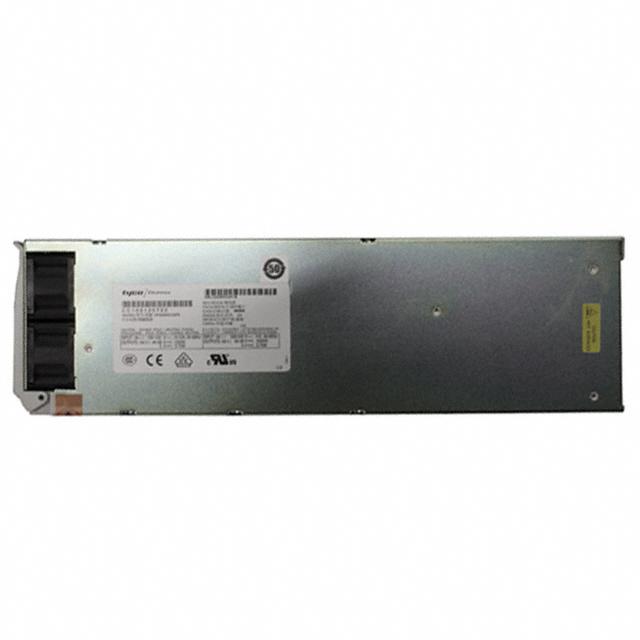
CP2000AC54 Front-End Power Supply
Input: 100-120/200-240 Vac; Outputs: ±54 Vdc at 2000W; 5 Vdc at 4W
Features
Compact 1-RU form factor providing 20 W/in3
Constant power from 52 – 58 Vdc
2000W from nominal 200 – 240 Vac
1200W from nominal 100 – 120 Vac
Output voltage programmable from 44V – 58 Vdc;
Applications
48Vdc distributed power architectures
Power over Ethernet
Routers/Switches
VoIP/Soft Switches
LAN/WAN/MAN applications
File servers
Indoor wireless
Telecommunications equipment
Enterprise Networks
SAN/NAS/iSCSI applications
Advanced workstations
output defaulted to 54V
PMBus compliant dual I2C and RS485 serial bus
communications
Power factor correction (meets EN/IEC 61000-3-2
and EN 60555-2 requirements)
Tested to IEEE802.3 Compliance, 2250 output***
isolation to chassis/signals for POE applications.
(see ordering info)
DC Output over-voltage and over-current
protection
AC Input over-voltage and under-voltage protection
Over-temperature warning and protection
Redundant, parallel operation with active load
sharing and redundant +5V Aux power
Remote ON/OFF
Hot insertion/removal (hot plug)
Four front panel LED indicators
UL* Recognized to UL60950-1, CAN/ CSA† C22.2
No. 60950-1, and VDE‡ 0805-1 Licensed to
IEC60950-1
CE mark meets 2006/95/EC directive§
Internal variable-speed fan control
The CP2000AC54 Front-End Power Supplies in the Compact Power Line platform are specifically
designed to operate as an integral part of a complete distributed power system. The high-density, front-toback airflow rectifier is designed for minimal space utilization and is highly expandable for future growth. It
is provided with many features including PoE isolation, RS485 and dual-redundant I2C communications
busses that allow it to be used in a broad range of applications. The flexible feature set makes this frontend power supply an excellent choice for applications requiring modular ac-to-dc bulk intermediate
voltages, such as in distributed power.
*
†
‡
§
UL is a registered trademark of Underwriters Laboratories, Inc.
CSA is a registered trademark of Canadian Standards Association.
VDE is a trademark of Verband Deutscher Elektrotechniker e.V.
This product is intended for integration into end-user equipment. All the required procedures for CE marking of end-user
equipment should be followed. (The CE mark is placed on selected products.)
** ISO is a registered trademark of the International Organization of Standards.
*** For PoE applications, order the CP2000AC54PEZ, which is 100% factory hipot-tested per IEEE802.3.
�Data Sheet
Compact Power Line
CP2000AC54 Front-End Power Supply
Specifications
Input
Parameter
Min
Typ
Max
Startup Input Voltage
1200W Operation
2000W Operation
85
175
150
Permitted Excursions
275
300
Surges
300
325
Input Frequency
47
120/200/240
200/240
275
275
175
63
13.3
11.2
11.8
9.9
Input Current
Inrush Transient
25
Input Leakage Current
1.5
Power Factor
Vac
Measured at 25°C for all line conditions; does
not include X-Capacitors charging.
mA
Measured at 265Vac, 60Hz
From 50% to 100% load.
90
93
Holdup Time
At 100 Vac
At 120 Vac
At 200 Vac
At 240 Vac
Apk
0.98
85
88
If started within low input line range.
If started within high input line range.
Will derate to 80% of full load; will shutdown
below 150Vac.
May not meet all requirements, but will
maintain output regulation.
May shut down but will not get damaged.
Hz
A
35
Notes
The power supply automatically configures its
operating mode based on the voltage level it
reads on first turn ON. (This information is
retained as long as internal bias is maintained.)
85
175
Operating Voltage Range
1200W Configuration
2000W Configuration
2000W Configuration
Efficiency
Units
%
15
ms
20
At 100 Vac with Vout > 52V and Pout > 50%.
At 230 Vac with Vout > 52V and Pout > 50%.
Measurement starts at zero crossing of the ac
voltage. Alarm issued via PFW signal going LO
5 ms prior to output voltages going out of limits.
Measurements made at 65% full load and
voltage allowed to decay to 49.5V.
For loads below 1200W.
Main Output
Parameter
Min
Typ
Maximum Output Power
Output Voltage Setpoint
Setpoint Accuracy
Overall Regulation
Output Voltage Margin
Maximum Output Current
Current Share
Lineage Power
Max
1200
2000
54
Units
Notes
W
At low-line input from 100-120Vac nominal.
At high-line input from 200-240Vac nominal.
Vdc
Output floats with respect to frame ground.
-1
+1
%
-2
+2
%
44
58
Vdc
Configured by hardware setting.
42
58
Vdc
Set either by I2C or RS485
23
38.5
A
10
%FL
Includes all variations due to specified load
range, drift, and environmental conditions.
At 1200W, 52V and 100-120Vac.
At 2000W, 52V and 200-240Vac.
Maintains tolerance to the average of all other
rectifiers. Loads > 25%FL
2
�Data Sheet
Compact Power Line
CP2000AC54 Front-End Power Supply
Specifications (continued)
Output (continued)
Parameter
Min
Typ
Max
Units
250
500
2
mVrms
mVpk-pk
mVrms
5,000
F
2
s
ms
s
%
Output Ripple
RMS (5Hz to 20MHz)
Peak-to-Peak (5Hz to 20MHz)
Psophometric Noise
External Bulk Load Capacitance
0
Turn-On
Delay
1
Rise Time - Standard (PMBus)
2
-Telecom (RS-485)
Overshoot
5
100
5
Load Step Response
I
V
Response Time
Overload
Power Limit
3
Current Limit Inception
Over-voltage
Delayed
Immediate
Latchoff
50
2000
102
Auto-recoverable
Monotonic Turn_On from 30% to 100% of Vnom
above -5°C operation. Monotonic Turn_On from
60% to 100% of Vnom below -5°C operation.
108
W
%FL
60
65
Vdc
Vdc
I/t slew rate 1A/µs.
Settling time to within regulation requirements.
Down to -52Vdc
Hiccup current limit. (FL = 38.5A)
200msec delayed shutdown to be implemented.
Instantaneous shutdown above this point.
Three restart attempts may be implemented within a one minute window prior to a latched
shutdown
Over-temperature
Warning
Shutdown
Measured with 20MHz bandwidth under any
condition of loading. Minimum load is 1A.
External capacitance can be increased but the
power supply will not meet its turn-ON rise time
requirement.
%FL
Vdc
ms
2.0
2
Notes
5
°C
20
Implemented prior to commencement of an OT
shutdown
Below the maximum rating of the device being
protected
°C
Temperature hysteresis of approximately 10°C provided between shutdown and restart.
1. Below -5°C, the rise time is approximately 5 minutes to protect the bulk capacitors.
2. Complies with GR947 which calls for a minimum rise time proportional to output load.
3. Fold-down current limit is programmed as a default to permit system start-up when units are plugged in one at a time. Latchoff mode current limit can be activated via an I2c command.
Auxiliary Output
Parameter
Min
Typ
Output Voltage Setpoint
Output Current
Overall Regulation
Units
0.75
A
-5
+10
%
100
mVpk-pk
50
Over-voltage Clamp
110
Notes
Vdc
0.005
Ripple and Noise
Over-current Limit
Max
5
7
Vdc
175
%FL
20MHz bandwidth
Physical
Length (in./mm)
13.85 / 351.8
Width (in./mm)
4.00 / 101.6
Height (in./mm)
1.66 / 42.2
Weight (lb/kg)
4.6 / 2.1
Lineage Power
3
�Data Sheet
Compact Power Line
CP2000AC54 Front-End Power Supply
Specifications (continued)
Environmental
Parameter
Min
Ambient Temperature
Operating
Ambient Derating
2
Power Derating
Storage Temperature
Humidity
Max
Units
Notes
45
1
2
°C
°C
%/°C
%/°C
Air inlet from sea level to 5,000 feet.
Per 1,000 feet above 5,000 feet.
Up to 55°C
From 55 to 75 °C
-40
85
°C
5
95
%
-5
Typ
1
1
Relative humidity, non-condensing
Shock and Vibration
Operational Test
Test Levels
Drop and Tip Over
Earthquake Rating
IEC 68-2
IEC 721-3-2
IEC 68-2-31
4
Acoustic Noise
45
Harmonic Emissions
Radiated Emissions
Zone
4
Per Telcordia GR-63-CORE, all floors, when
installed in CP Shelf.
Noise is proportional to fan speed, load and
ambient temperature.
dBA
Per EN/IEC61000-3-2
FCC and CISPR22 (EN55022) - Class B
3
Conducted Emissions - ac
FCC and CISPR22 (EN55022) Class B
Telcordia GR-1089-CORE - Class A
Conducted Emissions - dc
Telcordia GR-1089-CORE and CISPR22 (EN55022) - Class A
ESD
Error free per EN/IEC 61000-4-2 Level 4 (8 kV contact discharge, 15 kV air discharge).
Radiated Immunity
Error free per EN/IEC 61000-4-3 Level 3 (10 V/m).
Electrical Fast Transient Burst
Error free per EN/IEC 61000-4-4 Level 3 (2 kV, 5 kHz repetition rate)
Lightning Surge
Error Free
Damage Free
EN/IEC61000-4-5 Level 4 (4 kV common mode, 2 kV differential mode).
ANSI C62.41 Level A3 (6 kV common and differential mode)
Conducted Immunity
Error free per EN/IEC 61000-4-6 Level 3 (10Vrms).
Reliability (calculated)
Isolation
Input-Chassis/Signals
Input - Output
Output-Chassis/Signals
Service Life
400,000
1500
3000
2250
10
Hours
At ambient of 25°C at full load per Telcordia SR332, Reliability Prediction for Electronic Equipment,
Method I Case III.
Vrms
Vrms
Vdc
Per EN60950-1.
Consult factory for testing to this requirement
Per IEEE802.3.
Years
25°C ambient, full load excluding fans.
1. Designed to start at an ambient as low as -40°C, but may not meet operational limits until above -5°C.
2. Power derating shall consider only temperature variations at nominal line (100 – 120, 200 – 240Vrms). The unit may derate
faster if the input line is below nominal.
3. Class B radiated emmissions compliance requires the addition of a ferrite bead to each power line cord at the shelf-end of the
cable. See the figure below.
4. Radiated emissions compliance was met using a Lineage Power shelf. This shelf includes output common and differential mode
capacitors that assist in meeting compliance.
Lineage Power
4
�Data Sheet
Compact Power Line
CP2000AC54 Front-End Power Supply
Status and Control
The rectifier provides three means for
monitor/control: analog, PMBus compliant I2C, or
RS485 for interfacing to Lineage Power controllers
or battery plants.
Details of analog controls are provided in this data
sheet under Signal Definitions. Lineage Power will
provide separate application notes on PMBus
protocol for users to interface to the CPL rectifiers.
Contact your local Lineage Power representative
for details.
Hot Plug
Module Present Signal: This signal has dual
functionality. It can be used to alert the system
when a module is inserted. Has a 500 resistor in
series between this signal and Logic GRD. An
external pull-up should not raise the voltage on the
pin above 0.25Vdc. If raised the pin is raised to
5Vdc the write_protect feature of the EEPROM is
enabled.
Protocol Select: Establishes the communications
mode of the power supply, between analog/I2C and
RS485 modes. For RS485, connect a 10kΩ pulldown resistor to 54_OUT(-DC).
Enable: On/Off control when either PMBus
communications or analog functions are utilized as
configured by the Protocol pin. This pin must be
pulled low to turn ON the main output of the power
supply. The power supply will turn OFF if either the
Enable or the ON/OFF pin is released. The Enable
function does not work with the RS-485 protocol.
This signal is referenced to Logic_GRD.
When rapidly extracting and reinserting modules
care should be taken to allow for discharging the
internal bias supply so that a predictable restart
could be achieved. The way to ensure that the
circuit sufficiently discharges is to observe the
spinning of the fans after an extraction. The unit
should not be reinserted until the fans stop
spinning.
All signals are referenced to Logic GRD unless
otherwise noted. See the Signal Definitions Table
at the end of this document for further description
of all the signals.
ON/OFF: This is a short pin utilized for hot-plug
applications to ensure that the power supply turns
OFF before the power pins are disengaged. It also
ensures that the power supply turns ON only after
the power pins have been engaged. Must be
connected to 54_OUT (-DC).
Input Signals
Output Signals
Control Definitions
Margining: Setpoint of the rectifier can be changed
via this input pin. Programming can be either a
voltage source or a resistance divider. The
margining pin is connected to 3.3Vdc via a 10kΩ
resistor inside the rectifier. See graphs below.
10k
3.3Vdc
-46
-44
Vcontrol
Vprogram
Output Setpoint (Vdc)
-58
Alert #: PMBus interrupt signal.
Fault: This signal goes LO for any failure that
requires rectifier replacement. Some of these faults
may be due to:
Fan failure
Over-temperature condition
Over-temperature shutdown
Over-voltage shutdown
Internal Rectifier Fault
Power Capacity: A HI on this pin indicates rectifier
configured for 2000W operation; a LO indicates
rectifier configured for 1200W operation.
0 0.1
An open circuit on this pin reverts the voltage level
back to the original setting.
Lineage Power
5
�Data Sheet
Compact Power Line
CP2000AC54 Front-End Power Supply
Alarm Table
Power Supply LED State
AC OK
DC OK
Service
Fault
Green
Green
Amber
Red
1
1
0
0
Condition
OK
Thermal Alarm
(5C before shutdown)
Thermal Shutdown
Defective Fan
Blown AC Fuse in Unit
No AC
很抱歉,暂时无法提供与“CC109120722”相匹配的价格&库存,您可以联系我们找货
免费人工找货