CLP0212DC Open Frame Power Supply
DATASHEET
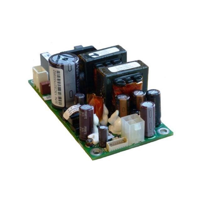
CLP0212DC Open Frame Power Supply
48VDC Input; 12VDC Output; 200W Output Power
In a small, 2x4-inch footprint, the
12Vdc single-output CLP0212DC
open-frame power supply delivers
high efficiency. With its small size, the
CLP series is specifically designed to
handle power challenges associated
with tight space and low airflow.
Description
18W/in3 power density in a 1U high,
less form
the
a broad range of
in new products—from
computing and data storage—for
(OEMs). It delivers greater than 90
typical power efficiency and
output at +50˚C
with higher
temperature operation possible at derated output The
utilizes a unique design approach at
power level,
leveraging zeroswitching
. Protection features include
overvoltage
Offering a
Features
•
Reverse input voltage protection
•
Output overcurrent protection (non-latching)
•
Compact size 50.8 mm x 101.6 mm x 36.1 mm
(2 in x 4 in x 1.4 in) with density of 18W/in3
•
Overtemperature protection
•
•
Universal DC Input Range (36 – 75VDC)
Output overvoltage protection
•
•
Output voltage of 12V (adjustable ±5%)
Up to 2ms of holdup time
•
•
Maximum output current of 16.7A@ 12Vout (200W)
Parallelable with current sharing
•
•
Standby output of 5V @ 0.25A
Conducted EMI - meets CISPR22 (EN55022) and FCC
Class A requirements
•
Full load capability at 50ºC and 1m/s (200LFM) airflow
with derating at higher temperatures or lower airflows
•
Compliant to RoHS II EU “Directive 2011/65/EU”
•
•
Remote ON/OFF
UL and cUL approved to UL/CSA62368-1, TUV
(EN62368-1), CE Mark (for LVD) and CB Report available
•
Remote ON/OFF
•
ISO** 9001 and ISO 14001 certified manufacturing
facilities
Page 1
© 2020 ABB. All rights reserved.
�Technical Specifications
Absolute Maximum Ratings
Stresses in excess of the absolute maximum ratings can cause permanent damage to the device. These are absolute stress
ratings only; functional operation of the device is not implied at these or any other conditions in excess of those given in the
operations sections of the data sheet. Exposure to absolute maximum ratings for extended periods can adversely affect the
device reliability.
Parameter
Device
Min
Max
Unit
Input Voltage - Continuous
All
36
75
Vdc
Operating Ambient Temperature
(in sealed enclosure applications with thermally conductive pad
to enclosure, PO,max = 110W)
All
-40
85
°C
All
-40
85†
°C
Storage Temperature
All
-40
85
°C
Humidity (non-condensing)
All
5
95
%
Altitude
All
5000
m
‡ Startup at -40ºC is limited to 80% of maximum load (160W) for all versions.
* Unit is capable of operation up to 85ºC ambient for brief periods of time provided humidity is kept below 40%. Sustained operation at 85ºC when power loading is
at or near the maximum rated value can degrade reliability of the product.
† Ambient temperature outside the sealed enclosure containing the power supply.
Electrical Specifications
Parameter
Device
Min
Typ
Max
Unit
Operating Input Voltage
Input Current
Inrush Transient Current (Tamb = 25ºC)
All
All
All
36
48
75
6.5
100
Vdc
Adc
A Peak
Leakage Current to earth ground
All
2
mA
Output Voltage Setpoint
Output Voltage Tolerance (due to set point, temperature variations,
load and line regulation)
Output Voltage Adjustment Range
Output Remote Sense Range
Output Load Regulation
Output Line Regulation
All
12
Vdc
All
-2
2
%
All
All
All
All
11.4
12.6
250
1.5
0.5
Vdc
mVdc
%Vout
%Vout
All
180
mV p-p
Dynamic Load Response – 50% to 75% load transient, 0.1A/µs slew
rate
Output voltage deviation
Settling Time
Output Current
All
All
All
5%
500
16.7
%
µs
Adc
Output Current Limit Inception
All
Maximum Output Capacitance
All
Standby Output Voltage
All
Output Ripple and Noise – measured with 0.1µF ceramic capacitor in
parallel with 10µF tantalum capacitor, at 25°C
Peak-to-peak (20MHz Bandwidth)
Standby Output Current
All
Efficiency: VIN = 48Vdc, 20% load
50% load
All
100% load
1
Output ripple
Holdup
Timeis–300mV
100% p-p
loadmaximum at -40°C. To reduce further, additional external capacitance needed.
All
(Vout≥ 10.8VDC, Tamb = 25°C, 200W, VIN = full range)
Page 2
© 2020 ABB. All rights reserved.
0
115
% IO,max
5000
5
———-
2
90.0
93.0
92.0
µF
Vdc
0.25
———-
Adc
%
%
%
ms
�Technical Specifications (continued)
Isolation Specifications
Parameter
Isolation Voltage – Input to output
Device
Min
All
Max
Unit
1000
Vdc
General Specifications
Parameter
Device
Symbol
Typ
Unit
Calculated Reliability based on Telcordia SR-332 Issue 2: Method 1 Case 3 (VIN=48Vdc, Io = 16.7A, TA = 40ºC, airflow 200LFM,
90% confidence)
All
FIT
MTBF
1,011.9
988,276
109/Hours
Hours
Weight
All
185
6.5
g
oz.
Feature Specifications
Parameter
On/Off Signal Interface – signal referenced to GND
Logic Low (Power Supply ON)
Input Low Current
Input Low Voltage
Logic High (Power Supply OFF)
Input High Current
Input Voltage
Delay from ON/OFF being enabled to start of output voltage rise
Output Voltage Rise Time (from 10 to 90% of final value)
Delay from Input being applied to standby output being in
regulation
Delay from Input being applied to all outputs being in regulation
Output Overvoltage Protection (for main output currents
above 0.1A)
Device
Min
Typ
Max
Unit
All
All
7
1
mA
V
All
All
All
600
5.5
50
µA
V
ms
All
5
ms
All
2
s
All
2
s
All
13.8
All
33
18
Vdc
36
Vdc
Input Undervoltage lockout3
Turn-on Threshold (100% load)
35
Turn-off Threshold (100% load)
DC OK – open collector, High when output available
2
3
Sink Current
All
4
mA
Maximum Collector Voltage
All
12
V
Holdup time is reduced at cold temperatures
The undervoltage lockout thresholds vary with output load current level – decreasing as the load goes down
Page 3
© 2020 ABB. All rights reserved.
�Technical Specifications (continued)
Environmental Specifications
Parameter
2
3
Device
Specification
Conducted Emissions
Input Harmonics
ESD
Radiated Immunity
All
All
All
All
CISPR22 (EN55022) Class B with 3dB margin
EN61000-3-2
IEC 61000-4-2, Level 3
CISPR22 (EN55022) Class B with 3dB margin
Electrical Fast Transient Common Mode
All
IEC 61000-4-4, Level 3
Surge Immunity
All
Conducted RF Immunity
Voltage Dips, Interruptions
All
All
IEC 61000-4-5; ±1kV common mode and differential mode, unit passes criteria A
(normal performance; impedance is 2 Ohms for differential and common mode.)
IEC 61000-4-6, Level 3
-53Vin, 80% load, Dip 100% duration 4ms, Criteria (A)
Shock and Vibration
Operating Shock
All
Three shocks, 15G peak, 11ms sine wave, two axes
Non-Operating Shock
All
Three shocks, 50G peak, 11ms sine wave, two axes
Operating and Non-Operating Vibration
All
5 – 9Hz, 0.5” double amplitude, 2G Peak, 0.5 oct./min., 2 cycles
9-500Hz, 4G pk-pk, 0.5 oct/min., 2 cycles
Holdup time is reduced at cold temperatures
The undervoltage lockout thresholds vary with output load current level – decreasing as the load goes down
Page 4
© 2020 ABB. All rights reserved.
�Technical Specifications (continued)
Power Derating for Forced Air Flow Application
Derating under transverse airflow for various input voltages.
Derating under longitudinal airflow for various input voltages.
Page 5
© 2020 ABB. All rights reserved.
�Technical Specifications (continued)
Safety Considerations
The
power supply is intended for inclusion in other
and the installer must ensure that it is in compliance
with all
of the end application.
product is
only for inclusion by professional installers within other
and must
be
as a
The power
supply
Class 1,
with the
60950
Component)
(Canadian Approval by
Feature Descriptions
Standby Power Supply
A standby output in the CLP0212DC power supply of 5V, comes on
when DC input in the operating range is applied.
Remote On/Off
All versions of the CLP0212DC power supply feature a
TTL-compatible On/Off control input. The power supply turns ON
when the On/Off input goes low, and turns OFF when the input
goes high. Note that if the On/Off pin is left unconnected, the
power supply main output remains off.
Figure 9 shows the circuit configuration for using the On/Off pin.
Either a suitable semiconductor device such as a BJT or FET or a
mechanical switch can be used to turn the power supply On and
Off. The switch must be capable of handling the On/Off pin
current which may be up to 6mA when closed. The switch On
voltage drop must also be sufficiently small so that the photo
diode inside the power supply is turned ON when the external
switch is ON.
Note that the standby output voltage is 5V. If no On/Off control is
desired, the On/Off pin can be externally connected to the COM
pin and the power supply will automatically turn ON when DC
input is within range.
Output Voltage Adjustment
Fig. 10. Diagram showing location of the potentiometer used to
adjust the power supply output voltage.
The output voltage can be adjusted between 11.4V and 12.6V using a
potentiometer on the power supply. See Fig. 10 for a diagram
showing location of the potentiometer.
Remote Sense
The power supply has both positive and negative remote sense
connections that can be connected to the positive and negative rails
of the main output near the load. Care should be taken in routing the
sense lines to ensure that noise is not picked up or that additional
filtering elements that affect the stability of the power supply are not
used. The power supply will operate without the remote sense
connections being made, however if remote sense near the load is
not used it is recommended that the remote sense lines be
connected directly to the main output terminals.
Overcurrent Protection
To provide protection in a fault condition (output overload), the
power supply is equipped with internal current-limiting circuitry and
can endure current limiting continuously. At the point of current-limit
inception, the unit enters hiccup mode. The power supply operates
normally once the output current is brought back into its
specified range.
Overvoltage Protection
Overvoltage protection is a feature of the CLP0212DC power
supply that protects both the load and the power supply from an
output overvoltage condition. When an overvoltage occurs, the
power supply shuts down and goes into hiccup mode until the
overvoltage condition is removed. It is not necessary to recycle the
input to restart the power supply when this protection
is activated.
Reverse Input Voltage Protection
Fig. 9. Schematic showing ON/OFF circuitry.
Page 6
© 2020 ABB. All rights reserved.
Reverse Input Voltage Protection is a feature of the CLP0212DC
power supply that protects the power supply from damage if a
reverse voltage is applied to the input.
�Technical Specifications (continued)
Overtemperature Protection
Heat Transfer via Convection
The CLP0212DC also features overtemperature protection in order to
provide additional protection in a fault condition. The power supply
is equipped with a thermal shutdown circuit which detects excessive
internal temperatures and shuts the unit down. Once the power
supply goes into overtemperature shutdown, it will cool before attempting to restart. The overtemperature protection circuit will
typically activate when the unit is operated at 200W output with an
ambient temperature of 60ºC and 1m/s (200LFM) airflow.
Increased airflow through the power supply enhances the heat
transfer via convection. Figure 11 shows the preferred airflow
direction. Contact your GE Energy technical representative for
derating information in other airflow directions.
Note: Under Natural Convection cooling conditions, the
maximum load is restricted to 100W as OTP will be triggered at
higher loads.
Input Undervoltage Lockout
At input voltages below the input undervoltage lockout limit, power
supply operation is disabled. The power supply will begin to operate
at an input voltage above the undervoltage lockout turn-on
threshold. Note that the undervoltage lockout limits are load
dependent and the power supply turns ON and can operate at much
lower input voltage levels when at light or no load.
DC OK
Fig. 11. Preferred airflow direction for cooling.
The CLP0212DC provides a DC OK signal that indicates when the
output has come up and is in regulation. This is an open-collector
type signal that goes high when the output is available and
within regulation.
Operation in a Sealed Enclosure
Power Good LED
A green LED (located next to HDR3) illuminates when the main
output voltage is above 10V.
Paralleling/Load Share
The CLP0212DC power supply can also be operated in a sealed
enclosure provided proper means for removing heat from the
power supply are used. Figure 12 shows an arrangement where a
thermally conductive pad is used to transfer heat from the bottom
of the power supply into the enclosure. Under such conditions, the
power supply is capable of reduced power operation as shown in
Table 1. Note that the Ambient Temperature shown in Table 1 is
that outside the sealed enclosure, the CLP0212DC may see higher
ambient temperatures.
This power supply can be paralleled to provide larger load currents
than can be delivered from a single power supply. Up to four power
supplies may be paralleled. Paralleling is accomplished by connecting
the Current Share signals of multiple power supplies together. At
load current levels above 20%, the output currents of multiple power
supplies will be within ±5% of the full load value.
If remote sense is used when paralleling is employed, the remote
sense connection points should be common to both power supplies.
For applications where redundancy among paralleled power supplies
is desired, ORing diodes or other active ORing circuitry needs to be
connected in series with each output.
Thermal Considerations
The power supply can be operated in a variety of thermal
environments; however sufficient cooling should be provided to
ensure reliable operation.
Considerations include ambient temperature, airflow, power supply
dissipation and the need for increased reliability. A reduction in the
operating temperature of the power supply will result in increased
reliability. The thermal data presented here is based on
measurements taken in a wind tunnel.
Page 7
© 2020 ABB. All rights reserved.
Fig. 12. Example arrangement of the CLP0212DC for sealed
enclosure applications.
Enclosure Outside Surface (°C)
Enclosure Inside
Ambient (°C)
Resistive Load
(W)
on CLP0212DC
50
85
200
55
92
190
Table 1. Output Power Capability when the CLP0212DC is operated
in a sealed enclosure with thermal pad for conduction cooling.
(Enclosure Application; With 200W resistive load inside enclosure.)
Note: The enclosure outside ambient temperature measured at 2 inches
above enclosure.
�Technical Specifications (continued)
Mechanical Outline (CLP0212DC)
Dimensions are in millimeters.
Tolerances: x.x mm ± 0.5mm [unless otherwise indicated] / x.xx mm ± 0.25mm
TOP VIEW
SIDE VIEW
3D VIEW
Page 8
© 2020 ABB. All rights reserved.
�Technical Specifications (continued)
Connector Information
Connector
Device
Min
DC Input Connector (HDR1)
5-1376382-1 from Tyco or equivalent
1376388-1 from Tyco or equivalent
DC Output Connector (HDR2)
39-28-1043 from Molex or equivalent
-39-01-2040 from Molex or equivalent
10114829-13108LF from Amphenol or
equivalent
Signal Connector** (HDR3)
10114826-00008LF Housing from Amphenol
or equivalent
10114827-004LF Mating pin from Amphenol
or equivalent
Pinout Information
DC Input Connector (HDR1)
Pin 1
Pin 2
DC Output Connector (HDR2)
Line
Neutral
Pin 1
Pin 2
Pin 3
Pin 4
VO
VO
RTN
RTN
Signal Connector (HDR3)
Pin 1
Pin 2
Pin 3
Pin 4
Current Share
+S (Remote Sense +)
-S (Remote Sense -)
Remote On/Off
Pin 5
DC-OK (Output OK)
Pin 6
COM (Output Return)
Pin 7
COM (Output Return)
Pin 8
Standby Output
Ordering Information
Device
Code
Input
Voltage
Range
Output
Voltage
Output
Current
On/Off
Control
Standby
Supply
Temperature
Range
Comcode
CLP0212DCS
X5Z01C
36 – 75Vdc
12.OVdc
16.7A
Negative
Logic
5V@0.25A
-40 to 85ºC
CLP0212DCSX5Z01C
Page 9
© 2020 ABB. All rights reserved.
�ABB
601 Shiloh Rd.
Plano, TX USA
Go.ABB/Industrial
We reserve the right to make technical changes or modify the
We reserve all rights in this document and in the subject matter and
contents of this document without prior notice. With regard
illustrations contained therein. Any reproduction, disclosure to third
to purchase orders, the agreed particulars shall prevail.
parties or utilization of its contents – in whole or in parts – is
ABB does not accept any responsibility whatsoever
forbidden without prior written consent of ABB.
for potential errors or possible lack of information in this
document.
Copyright© 2020 ABB
All rights reserved
Page 10
© 2020 ABB. All rights reserved.
�