DATASHEET
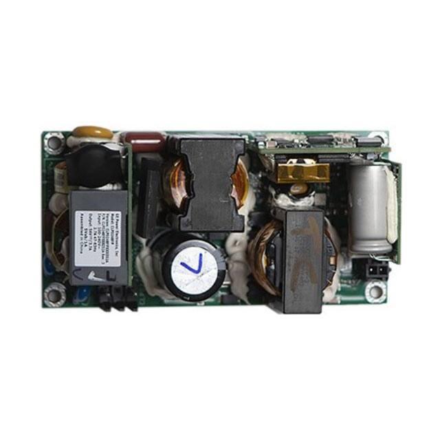
CLP0248 Open Frame Power Supply
90 - 265Vac Input; 48V/4.16A or 54V/3.7A Output; 200W Output Power
.
Description
Applications include: Industrial
Equipment | Telecommunications Equipment | SG Pico Base-Stations
Features
•
Compact size 50.8 mm x 101.6 mm (2 in x 4 in x 1.40 in)
with density of 18 W/in3
•
Supports paralleling with active current sharing, as long as
OR-ing components are added
•
Universal AC Input Range (90 ~ 265VAC permanently,
350VAC for 5 minutes)
•
IEC61000-4-5, Level 4 (2kV/4kV)
•
Output voltage of 48V or 54V with ±3V adjustable voltage
•
Output overcurrent protection (non-latching)
•
•
Standby output of 5V/1A (5W)
Overtemperature and output over-voltage protections
•
•
Standby power consumption of 0.5W (with no load on the
standby output, and the main output inhibited)
Up to 11ms of holdup time at 200W out (with Vout at 42V
at the end)
•
High efficiency (88% at Full Load, 230VAC in, 25
•
Active power factor corrected input
•
•
Full load capability at 50
and 1m/s airflow with derating
at higher temperatures or lower airflows
Conducted EMI - meets CISPR22 (EN55022) and FCC Class
B requirements
•
Capable of >140W output in sealed enclosure applications,
•
with enclosure ambient at 55
, and an enclosure internal
temperature of 85
•
Compliant to RoHS2 EU Directive 2011/65/EU
•
PoE compliant, output to Earth isolation of 2250Vdc
See footnotes on page 4
Page 1
© 2020 ABB. All rights reserved.
)
•
UL and cUL approved to UL/CSA60950-1, TUV (EN609501), CE Mark (for LVD) and CB Report available
ISO** 9001 and ISO 14001 certified manufacturing facilities
�Technical Specifications
Absolute Maximum Ratings
Stresses over the absolute maximum ratings can cause permanent damage to the device. Functional operation of the device is
not implied at these or any other conditions over those given in the operations sections of the data sheet. Exposure to absolute
maximum ratings for extended periods can adversely affect the device reliability.
Parameter
Input Voltage - Continuous Operation
Device
Min
Max
Unit
All
90
265
Vac
For up to 10 seconds operation
All
90
275
Vac
For up to 5 minutes, may not operate, no damage
All
305
Vac
Operating Ambient Temperature
All
-40
85
°C
Storage Temperature
All
-40
85
°C
Humidity (non-condensing)
All
5
95
%
Altitude
All
5000
m
(see Thermal Considerations section)
Isolation Voltage—Input to output
All
3000
Vac
Input to safety ground
All
1500
Vac
Outputs to safety ground
All
2250
Vac
Electrical Specifications
Parameter
Operating Input Voltage
Input Source Frequency
Input Current (VIN = 90Vac)
Input Power Factor (230Vac, Full Load)
Inrush Transient Current (VIN = 265Vac, T amb = 25ºC)
Leakage Current to earth ground (VIN = 265Vac)
Output Voltage Adjustment Range
Output Voltage Setpoint
Output Voltage Tolerance (due to set point, temperature variations, load
and line regulation)
Output Voltage Adjustment Range
Output Remote Sense Range—Total
Device
Min
Typ
Max
Unit
All
All
All
All
All
All
All
201A
202A
90
47
115/230
50/60
265
63
2.7
Vac
Hz
ARMS
100
3.5
12.6
A Peak
mA
Vdc
Vdc
Vdc
0.95
11.4
48
54
All
-2
2
%
201A
202A
All
45
51
51
57
1
Vdc
Vdc
Vdc
Output Load Regulation
All
1
%Vout
Output Line Regulation
Output Ripple and Noise – measured with 0.1µF and 10µF capacitors
in parallel. Peak-to-peak (20MHz Bandwidth) (higher for the 54V
unit)
All
0.25
%Vout
201A
500
mV p-p
202A
550
mV p-p
All
2.4
V
All
2
Ms
Adc
Dynamic Load Response – 50% to 100% load transient,
1°/µs slew rate
Output voltage deviation
Settling Time
Output Current
Output Current Limit Inception
Output Current Capacitance
See footnotes on page 4
Page 2
© 2020 ABB. All rights reserved.
201A
0
4.16
202A
0
3.7
Adc
105
140
1000
% IO,max
µF
All
All
-continued on next page-
�Technical Specifications (continued)
Electrical Specifications con’t.
Parameter
Device
Min
Efficiency: VIN = 230Vac—20% load (Ta = +25 C)
50% load (Ta = +25 C)
100% load (Ta = +25C)
All
All
All
87.5
92
88
Typ
Max
Unit
%
%
%
Efficiency: VIN = 115Vac— 20% load (Ta = +25 C)
All
87
%
50% load (Ta = +25 C)
100% load (Ta = +25 C)
Holdup Time1 — 200W load
All
All
All
90
87
11
%
%
ms
General Specifications
Parameter
Device
Symbol
Typ
Unit
Calculated Reliability based on Telcordia SR-332 Issue 2:
Method 1 Case 3 (VIN=230Vac, Io = 3.7A, TA = 40ºC, airflow
200LFM, 90% confidence)
All
MTBF
>750,000
Hours
Weight
All
400
14.1
g
oz.
Feature Specifications
Parameter
Device
Min
Typ
Max
Unit
On/Off Signal Interface – signal referenced to zero
Logic Low (Power Supply ON)
Input Low Current
All
7
mA
Input Low Voltage
Logic High (Power Supply OFF)
Input High Current
Input Voltage
Delay from ON/OFF being enabled to start of output voltage rise
All
1
V
All
All
All
600
5.5
200
µA
V
ms
Output Voltage Rise Time (from 10 to 90% of final value)
All
Delay from Input being applied to all outputs being in regulation
All
Output Overvoltage Protection
100
ms
800
ms
201A
59
64.5
Vdc
202A
59
64.5
Vdc
Input Undervoltage lockout2
Turn-on Threshold (100% load)
All
75
81
90
Vac
Turn-off Threshold (100% load)
All
65
72
88
Vac
DC OK – open collector, High when output available
Sink Current
All
4
mA
Maximum Collector Voltage
All
12
V
Safety Specifications
Parameter
Device
Specification
Dielectric Withstand Voltage (between input and output)
All
Minimum of 4,250Vdc for 1 minute
Insulation Resistance (between input and output)
All
Minimum of 5 MΩ
All
Class 1, IEC60950, EN60950, with the following
deviations: Nemko, UL 60950 (Recognized Component), cUL (Canadian Approval by UL)
Safety Standards
See footnotes on page 4
Page 3
© 2020 ABB. All rights reserved.
�Technical Specifications (continued)
Environmental Specifications
Parameter
Device
Specification
Radiated Emissions4
Conducted Emission
ESD
Radiated Susceptibility4
All
All
All
All
CISPR22 Class B with 3dB margin
CISPR22 Class B with 6dB margin
IEC 61000-4-2, Level 3
IEC 61000-4-3, Level 3
Electrical Fast Transient Common Mode
All
IEC 61000-4-4, Level 3
Surge Immunity
Conducted RF Immunity
All
All
Input Voltage Dips
All
Input Harmonics
All
IEC 61000-4-5, Level 4
IEC 61000-4-6, Level 3
Output stays within regulation for either ½ cycle interruption or 25% dip from
nominal line for 1 second
IEC61000-3-2
Shock and Vibration
All
Per IPC-9592B, Class II
FOOTNOTES
*UL is a registered trademark of Underwriters Laboratories, Inc.
†
CSA is a registered trademark of Canadian Standards Association.
** ISO is a registered trademark of the International Organization of Standard
1
Output voltage is allowed to drop to 42Vdc at the end of the hold-up period.
2
Under-voltage lockout threshold may vary with output load current level – decreasing as load goes lower
Output current sharing is controlled by an analogue signal referenced to Vout-. Best current sharing performance is achieved when the two output voltages are set very close to each other.
Although the number of sharing units is limited to 2 in this document, more than two units may well share current adequately, but that is beyond the design intent, and beyond the development test plan. The units do not contain any output OR-ing device. For units connected in parallel, the customer will have to add external output OR-ing devices.
3
4
Shall meet when tested in a suitable enclosure
Page 4
© 2020 ABB. All rights reserved.
�Technical Specifications (continued)
Safety Considerations
Overcurrent Protection
The CLP0248 power supply is intended for inclusion in other
To provide protection in a fault condition (output overload), the
equipment and the installer must ensure that it is in compliance with
all the requirements of the end application. This product is only for
inclusion by professional installers within other equipment and must
not be operated as a stand-alone product. The power supply meets
power supply is equipped with internal current-limiting circuitry
and can endure current limiting continuously. At the point of
current-limit inception, the unit enters hiccup mode. The power
supply operates normally once the output current is brought back
Class 1, IEC60950, EN60950, with the following deviations: Nemko.
into its specified range.
UL 60950 (Recognized Component) C-UL (Canadian Approval by UL).
Overvoltage Protection
Input voltage can be up to 305Vac for up to 5 minutes.
Safety approval should include various input voltages, output
currents, ambient temperatures, and cooling regimes. This should
include 150W (or more) at 80C with conduction cooling. It should
Overvoltage protection is a feature of the CLP0212DC power
supply that protects both the load and the power supply from an
output overvoltage condition. When an overvoltage occurs, the
power supply shuts down and goes into hiccup mode until the
also include testing with the manufacturer’s intended cover in place.
overvoltage condition is removed. It is not necessary to recycle
Feature Descriptions
s activated.
the input to restart the power supply when this protection I
Standby Power Supply
Overtemperature Protection
A standby output of 5V in the CLP0248 power supply, comes on
The CLP0248 also features overtemperature protection in order to
when AC input in the operating range is applied.
provide additional protection in a fault condition. The power supply is
Remote On/Off
equipped with a thermal shutdown circuit which detects excessive
internal temperatures and shuts the unit down. Once the power
There is an On/Off control input. See the feature specification table
supply goes into overtemperature shutdown, it will cool before
for voltages and currents, and the pinout information table to find its
attempting to restart. The overtemperature protection circuit will
location.
typically trip when the unit is operated at 200W output with an
The main power supply turns ON when the Remote On/Off pin
input goes low (such as connect HDR3.4 (Remote On/Off)) and
HDR3.8 (Stand-by return)); turns OFF when the Remote On/Off
pin goes high (such as connect HDR3.4 (Remote On/Off)) and
HDR3.7 (5V stand-by output)). Note that if the Remote On/Off pin
is left unconnected, the power supply main output will remain off.
ambient temperature of 73ºC and 1m/s (200LFM) airflow, when input
voltage is 115Vac and 230Vac.
Input Undervoltage Lockout
At input voltages below the input under-voltage lockout limit, power
supply operation is disabled. The power supply will begin to operate
at an input voltage above the under-voltage lockout turn-on
Output Voltage Adjustment
threshold.
The output voltage can be adjusted between 11.4V and
DC OK
12.6V using a potentiometer on the power supply.
The power supply provides a DC OK signal that indicates when
the main output is operating normally. This is an open-collector
signal that goes high when the output is within regulation.
Power Good LED
A green LED on board the power supply illuminates when the main
output voltage is operating normally.
Assembling
Metal screw should be used to mount the unit and 4
mounting holes are connected to Earth well.
Remote Sense
The power supply has both positive and negative remote sense
connections that can be connected to the positive and negative rails
of the main output near the load. The power supply operates without
the remote sense connections being made.
Page 5
© 2020 ABB. All rights reserved.
Thermal Considerations
The power supply can be operated in a variety of thermal
environments; however sufficient cooling should be provided to
ensure reliable operation.
�Technical Specifications (continued)
Thermal Considerations con’t
Considerations include: ambient temperature, presence of a
enclosure. Under such conditions, CLP0248 is capable of reduced
power operation as shown in Table 1 .
cover, airflow, power supply dissipation and the need for
increased reliability. A reduction in the operating temperature of
the power supply will result in increased reliability. The thermal
data presented here is based on measurements taken in a
wind tunnel.
Low temperatures will adversely affect start-up. When the
ambient temperature is in the range -40C to -15C the unit might
not start up when the load is over 40% of rating. When the
ambient temperature is above -15C and the input voltage is above
115Vac the unit will start up into full load.
Heat Transfer via Convection
Increased airflow through the power supply enhances the heat
transfer via convection. Figure below shows the preferred airflow
direction. We will need derating data for airflow in other directions
as well.
Note that the Ambient Temperature shown in Table 1 is that outside
the sealed enclosure, the unit may see higher ambient temperatures.
Enclosure Outside
temp
25C
Enclosure inside
temp
55C
Max output
power
190W
40C
70C
170W
50C
80C
150W
55C
85C
140W
Table 1 Below– Output power capability when the CLP0248
is operated in a sealed enclosure with a thermal pad for
conduction cooling.
Current Sharing
The below figure describes the available output current with the
input voltage of 90Vac, 115Vac, 230Vac and 265Vac and with the
airflow of 200LFM.
It is intended that 2 identical power supplies will current share.
The current sharing is intended to produce a situation where the
two power supplies, if identically cooled, with exhibit similar
temperatures to each other.
The current sharing signal is referenced to Vout- so efforts must be
made to keep the Vout- lines short and of low impedance and noise.
The best current sharing performance will be achieved when the two
output voltages are set very close to each other.
Although the number of sharing units is limited to 2, more than two
units may well share current adequately. The units do not contain any
output OR-ing device. If connection in parallel is required, the
customer will have to add external output OR-ing devices.
Thermal Derating
CLP0248 can also be operated in a sealed enclosure provided proper
means for removing heat from the power supply are used. Following
Figure shows an arrangement where a thermally conductive pad is
used to transfer heat from the bottom of the power supply into the
Page 6
© 2020 ABB. All rights reserved.
�Technical Specifications (continued)
Mechanical Outline (CLP0248)
Dimensions are in millimeters.
Tolerances: x.x mm ± 0.5mm [unless otherwise indicated] / x.xx mm ± 0.25mm
TOP VIEW
SIDE VIEW
BOTTOM VIEW
minimum clearance of 6mm required on bottom of the unit
Page 7
© 2020 ABB. All rights reserved.
�Technical Specifications (continued)
Drawings (CLP0248)
The CLP0248 is fastened to standard M3 pillars by standard M3 screws. We recommend a type with a captive anti-vibration
washer, and here just as an example.
Wiring Accessories
ABB offers a wiring kit, as per table 2 (Device Codes). Drawings to be provided by Engineering, in due course. And the leads of CLP0248 are similar
to below.
Wire 1 – AC input – example of similar lead for illustration purposes only (CLP0248 lead uses positions 1 and 3, with 2 omitted for creepage and
clearance purposes)
Wire 2 – DC Power output – example of similar lead for illustration purposes only
Wire 3 – Controls and Signals – example of similar lead for illustration purposes only
Page 8
© 2020 ABB. All rights reserved.
�Technical Specifications (continued)
We will offer a cover, as per Table 2-Device Codes. (see next page). Here is an illustration of what it will look like.
Cover
Accessory
Connector Information
Connector
AC Input Connector (HDR1)
DC Output Connector (HDR2)
Auxiliary Connector (HDR3)
Device
Min
Molex 26-50-3030
Molex 09-50-8030 (4600273521P)
and 2 pieces of
Molex 08-52-0071 (4600273523P)
CVILUX CP3502P1V00
CVILUX CP3502S0010 (4600273537P)
and 2 pieces of
CVILUX CP35TN2BPES (CC408630867 )
Molex 53047-0810
Molex 51021-0800 (450020704)
and 8 pieces of
Molex 50058-8000 (450021150)
Pinout Information
AC Input Connector (HDR1)
Pin 1
Pin 2
Pin 3
Page 9
© 2020 ABB. All rights reserved.
Neutral
Not used
Line
DC Output Connector (HDR2)
Pin 1
Pin 2
Vout Positive
Vout Negative
Auxiliary (HDR3)
1-Sense Positive
2-Unused
3-Sense Negative
4-Remote On/Off
5-Current Share
6-Output OK
7-SV Standby Output
8-Stand-by Return
�Technical Specifications (continued)
Ordering Information
Device
Code
Input
Voltage
Range
Output
Voltage
Output
Current
On/Off
Control
Standby
Supply
Temperature
Range
Comcode
CLP0248FP
XXXZO1A
90 –
265Vac
48Vdc
4.16A
Negative
Logic
5V@0.25A
-40 to 85ºC
CLP0248FPXXXZO1A
CLP0248FP
XXXZ02A
90 –
265Vac
54Vdc
3.7A
Negative
Logic
5V@0.25A
-40 to 85ºC
CLP0248FPXXXZ02A
CLP0248CV
RXXZ01A
Metal
cover
accessory
NA
NA
NA
NA
NA
CLP0248CVRXXZ01A
CLP0248CB
LKTZ01A
50cm
lead kit
NA
NA
NA
NA
-40 to 85ºC
CLP0248CBLKTZ01A
Page 10
© 2020 ABB. All rights reserved.
�ABB
601 Shiloh Rd.
Plano, TX USA
Go.ABB/Industrial
We reserve the right to make technical changes or modify the
We reserve all rights in this document and in the subject matter and
contents of this document without prior notice. With regard
illustrations contained therein. Any reproduction, disclosure to third
to purchase orders, the agreed particulars shall prevail.
parties or utilization of its contents – in whole or in parts – is
ABB does not accept any responsibility whatsoever
forbidden without prior written consent of ABB.
for potential errors or possible lack of information in this
document.
Copyright© 2020 ABB
All rights reserved
Page 11
© 2020 ABB. All rights reserved.
�