Data Sheet
March 31, 2008
DS04-028 ver. 1.1 (Replaces DS04-028 ver. 1.0)
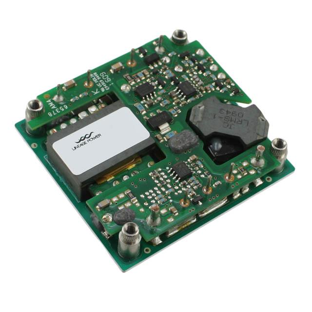
DW025 Triple Output-Series Power Modules:
36 Vdc to 75 Vdc Input; 25 W
Options
n
Short pins: 2.79 mm ± 0.25 mm
(0.110 in. ± 0.010 in.)
n
Negative logic remote on/off
n
Heat sink available for extended operation
Description
The DW025 Triple Output-Series Power Modules use
advanced, surface-mount technology and deliver high-quality, compact, dc-dc conversion at an economical price.
Features
n
Small size: 71.1 mm x 61.0 mm x 12.7 mm
(2.80 in. x 2.40 in. x 0.50 in.)
n
Low output noise
n
Industry-standard pinout
n
Metal case with separate case ground pin
n
2:1 input voltage range
n
Remote on/off (positive logic)
n
The maximum total output power of the DW025 Triple
Output-Series Power Modules is limited to 25 W. The
main output (VO1) is designed to deliver the entire
25 W. The auxiliary outputs (VO2 and VO3) can
provide a total of 22.5 W, as long as the total output
power does not exceed 25 W.
Efficiency greater than 80%, a wide operating
temperature range, and a metal case are additional
features of these modules.
UL* Recognized, CSA† Certified, and VDE
Licensed
n
Within FCC and CISPR Class A Radiated Limits
n
Higher accuracy output voltage clamp set point
n
The DW025 Triple Output-Series Power Modules are
dc-dc converters that operate over an input voltage
range of 36 Vdc to 75 Vdc and provide three outputs.
These modules offer extremely low noise levels with
industry-standard pinouts in a small footprint. Each
highly reliable and efficient unit features remote
on/off and current limit.
CE mark meets 73/23/EEC and 93/68/EEC
directives‡
Applications
n
Distributed power architectures
n
Telecommunications
* UL is a registered trademark of Underwriters Laboratories, Inc.
† CSA is a registered trademark of the Canadian Standards Association.
‡ This product is intended for integration into end-use equipment.
All the required procedures for CE marking of end-use equipment should be followed. (The CE mark is placed on selected
products.)
�DW025 Triple Output-Series Power Modules:
36 Vdc to 75 Vdc Input; 25 W
Data Sheet
March 31, 2008
Absolute Maximum Ratings
Stresses in excess of the absolute maximum ratings can cause permanent damage to the device. These are absolute stress ratings only. Functional operation of the device is not implied at these or any other conditions in excess
of those given in the operations sections of the data sheet. Exposure to absolute maximum ratings for extended
periods can adversely affect device reliability.
Parameter
Symbol
Min
Max
Unit
Input Voltage Continuous
VI
—
80
Vdc
I/O Isolation Voltage:
dc
Transient (1 minute)
—
—
—
—
500
850
V
V
Operating Case Temperature
TC
–40
100
°C
Storage Temperature
Tstg
–55
125
°C
Electrical Specifications
Unless otherwise indicated, specifications apply to all modules over all operating input voltage, resistive load, and
temperature conditions.
Table 1. Input Specifications
Parameter
Symbol
Min
Typ
Max
Unit
VI
36
48
72*
Vdc
II, max
—
—
2.0
A
Inrush Transient
i 2t
—
—
0.2
A2s
Input Reflected-ripple Current, Peak-to-peak
(5 Hz to 20 MHz, 12 µH source impedance;
TC = 25 °C; see Figure 18 and Design
Considerations section.)
—
—
25
—
mAp-p
Input Ripple Rejection (120 Hz)
—
—
60
—
dB
Operating Input Voltage
Maximum Input Current
(VI = 0 V to 75 V; IO = IO, max)
* Operation is specified to 75 V, provided the minimum load on Output 1 is at least 0.75 A. Safety agency reports specify 75 V maximum input.
Fusing Considerations
CAUTION: This power module is not internally fused. An input line fuse must always be used.
This encapsulated power module can be used in a wide variety of applications, ranging from simple stand-alone
operation to an integrated part of a sophisticated power architecture. To preserve maximum flexibility, internal fusing is not included; however, to achieve maximum safety and system protection, always use an input line fuse. The
safety agencies require a normal-blow, dc fuse with a maximum rating of 5 A in series with the ungrounded input
lead. Based on the information provided in this data sheet on inrush energy and maximum dc input current, the
same type of fuse with a lower rating can be used. Refer to the fuse manufacturer’s data for further information.
2
Lineage Power
�DW025 Triple Output-Series Power Modules:
36 Vdc to 75 Vdc Input; 25 W
Data Sheet
June 1997
Electrical Specifications (continued)
Table 2. Output Specifications
Parameter
Device
Symbol
Min
Typ
Max
Unit
Output Voltage
(Over all operating input
voltage, resistive load, and
temperature conditions until
end of life. See Figure 20.)
DW025ABK-M
VO1
VO2
VO3
VO1
VO2
VO3
4.80
10.80
–10.80
4.80
13.77
–13.77
—
—
—
—
—
—
5.20
13.70
–13.70
5.20
17.20
–17.20
Vdc
Vdc
Vdc
Vdc
Vdc
Vdc
Output Voltage Set Point
(VI = 48 V; TC = 25 °C;
IO1 = 2.0 A, IO2 = IO3 = 0.5 A)
DW025ABK-M
VO1, set
VO2, set
VO3, set
VO1, set
VO2, set
VO3, set
4.90
11.83
–11.83
4.90
14.84
–14.84
5.00
12.20
–12.20
5.00
15.30
–15.30
5.10
12.57
–12.57
5.10
15.76
–15.76
Vdc
Vdc
Vdc
Vdc
Vdc
Vdc
All
All
—
VO1
—
—
0.1
0.1
0.2
0.2
%
%
All
VO1
—
0.5
1.5
%
All
VO1
VO2, VO3
VO1
VO2, VO3
—
—
—
—
—
—
—
—
25
30
100
150
mVrms
mVrms
mVp-p
mVp-p
IO1
IO2, IO3
IO1
IO2, IO3
0.5
0.1
0.5
0.1
—
—
—
—
5.0
1.0
5.0
0.83
A
A
A
A
IO1
IO2, IO3
IO1
IO2, IO3
—
—
—
—
6
2
6
2
7.5
3.0
7.5
3.0
A
A
A
A
IO1
IO2, IO3
IO1
IO2, IO3
—
—
—
—
8
3
8
3
10.5
4.5
10.5
4.5
A
A
A
A
η
η
80
80
82
83
—
—
%
%
DW025ACL-M
DW025ACL-M
Output Regulation:
Line (VI = 36 V to 75 V)
Load (IO1 = IO, min to IO, max,
IO2 = IO3 = IO, min)
Temperature (TC = –40 °C to
+100 °C)
Output Ripple and Noise
(See Figure 19.):
RMS
Peak-to-peak (5 Hz to 20
MHz)
All
Output Current
(At IO < IO, min, the modules may
exceed output ripple
specifications.)
DW025ABK-M
Output Current-limit Inception
(VO = 90% of VO, nom and
minimum load on other
outputs.)
DW025ABK-M
Output Short-circuit Current
(VO = 1 V and minimum load on
other outputs.)
DW025ABK-M
Efficiency
(VI = 48 V; TC = 25 °C; see
Figures 13, 14, and 20.):
IO1 = 2.5 A, IO2 = IO3 = 0.5 A
IO1 = 2.0 A, IO2 = IO3 = 0.5 A
Lineage Power
DW025ACL-M
DW025ACL-M
DW025ACL-M
DW025ABK-M
DW025ACL-M
�DW025 Triple Output-Series Power Modules:
36 Vdc to 75 Vdc Input; 25 W
Data Sheet
March 31, 2008
Electrical Specifications (continued)
Table 2. Output Specifications (continued)
Parameter
Device
Symbol
Min
Typ
Max
Unit
All
All
VO1
—
—
—
80
1
—
—
mV
ms
All
All
VO1
—
—
—
80
0.5
—
—
mV
ms
Min
Typ
Max
Isolation Capacitance
—
0.02
—
µF
Isolation Resistance
10
—
—
MΩ
Max
Unit
113 (4.0)
g (oz.)
Dynamic Response
(ΔIO/Δt = 1 A/10 µs, VI = 48 V,
TC = 25 °C):
Load Change from IO = 50%
to 75% of IO, max:
Peak Deviation
Settling Time (VO < 10%
peak deviation)
Load Change from IO = 50%
to 25% of IO, max:
Peak Deviation
Settling Time (VO < 10%
peak deviation)
Table 3. Isolation Specifications
Parameter
Unit
General Specifications
Parameter
Min
Calculated MTBF (IO = 80% of IO, max; TC = 40 °C)
Weight
4
Typ
2,906,000
—
—
hours
Lineage Power
�DW025 Triple Output-Series Power Modules:
36 Vdc to 75 Vdc Input; 25 W
Data Sheet
June 1997
Feature Specifications
Unless otherwise indicated, specifications apply over all operating input voltage, resistive load, and temperature
conditions. See Feature Descriptions and Design Considerations for further information.
Parameter
Device
Symbol
Min
Typ
Max
Unit
Remote On/Off
(VI = 0 V to 75 V; open collector or equivalent
compatible; signal referenced to VI(–)
terminal. See Figure 21 and Feature
Descriptions.):
DW025XXX-M (positive logic)
Logic Low—Module Off
Logic High—Module On
DW025XXX1-M (negative logic)
Logic Low—Module On
Logic High—Module Off
Module Specifications:
On/Off Current—Logic Low
On/Off Voltage:
Logic Low
Logic High (Ion/off = 0)
Open Collector Switch Specifications:
Leakage Current During Logic High
(Von/off = 10 V)
Output Low Voltage During Logic Low
(Ion/off = 1 mA)
Turn-on Time
(IO = 80% of IO, max; VO within ±1% of
steady state)
Output Voltage Overshoot
All
Ion/off
—
—
1.0
mA
All
All
Von/off
Von/off
0
—
—
—
1.2
10
V
V
All
Ion/off
—
—
50
µA
All
Von/off
—
—
1.2
V
All
—
—
5
—
ms
All
—
—
0
5
%
DW025ABK-M
VO1
VO2
VO3
VO1
VO2
VO3
—
—
—
—
—
—
6
15
–15
6
19
–19
6.8
17
–17
6.8
21
–21
V
V
V
V
V
V
—
90
—
110
%Vo, nom
Output Overvoltage Clamp
DW025ACL-M
Output Voltage Set-point Adjustment Range
Lineage Power
All
�DW025 Triple Output-Series Power Modules:
36 Vdc to 75 Vdc Input; 25 W
Data Sheet
March 31, 2008
Characteristic Curves
12.30
12.25
OUTPUT VOLTAGE, VO (V)
INPUT CURRENT, II (A)
1.0
0.9
0.8
0.7
0.6
0.5
0.4
12.20
12.15
12.10
12.05
0.3
12.00
0.2
11.95
-40
0.1
0.0
-20
0
20
40
60
80
100
CASE TEMPERATURE, T (°C)
0
10
20
30
40
50
60
70
80
INPUT VOLTAGE, VI (V)
8-1102(C)
Figure 1. DW025 Triple Output-Series Typical Input
Characteristics
8-1079(C)
Figure 3. DW025 Triple Output-Series Typical Output Voltage Variation of 12 V Output Over
Ambient Temperature Range
15.60
15.55
OUTPUT VOLTAGE, VO (V)
OUTPUT VOLTAGE, VO1 (V)
5.01
5.00
4.99
4.98
4.97
15.40
15.35
15.30
15.25
15.20
15.10
-40
-20
0
20
40
60
80
100
CASE TEMPERATURE, T (°C)
-20
0
20
40
60
80
100
CASE TEMPERATURE, T (°C)
8-1080(C)
8-1078(C)
Figure 2. DW025 Triple Output-Series Typical Output Voltage Variation of 5 V Output Over
Ambient Temperature Range
6
15.45
15.15
4.96
4.95
-40
15.50
Figure 4. DW025 Triple Output-Series Typical Output Voltage Variation of 15 V Output Over
Ambient Temperature Range
Lineage Power
�DW025 Triple Output-Series Power Modules:
36 Vdc to 75 Vdc Input; 25 W
Data Sheet
March 31, 2008
Characteristic Curves (continued)
OUTPUT VOLTAGE, VO2 (V)
16.3
OUTPUT VOLTAGE, VO2 (V)
13.5
13.0
VI = 54 V, IO1 = 2.5 A, IO3 = 0.5 A
12.5
12.0
VI = 54 V, IO1 = 0.5 A, IO3 = 0.1 A
11.5
11.0
0.0
15.8
VI = 54 V, IO1 = 2.5 A, IO3 = 0.45 A
15.3
14.8
14.3
VI = 54 V, IO1 = 0.5 A, IO3 = 0.1 A
13.8
0
0.1
0.2
0.3
0.4
0.5
0.6
0.7
0.8
OUTPUT CURRENT, IO2 (A)
0.1
0.2
0.3
0.4
0.5
0.6
0.7
0.8
0.9 1.0
OUTPUT CURRENT, IO2 (A)
8-1103(C)
8-1105(C)
Figure 7. DW025ACL-M Typical Load Regulation
Figure 5. DW025ABK-M Typical Load Regulation
OUTPUT VOLTAGE, VO2 (V)
16.8
OUTPUT VOLTAGE, VO1 (V)
13.5
13.0
VI = 54 V, IO2 = IO3 = 0.1 A
12.5
12.0
16.3
15.8
VI = 54 V, IO2 = IO3 = 0.1 A
15.3
VI = 54 V, IO2 = IO3 = 0.45 A
14.8
14.3
VI = 54 V, IO2 = IO3 = 0.5 A
13.8
0.0
11.5
11.0
0.4
0.9
1.4
1.9
2.4
2.9
3.4
3.9
4.4
OUTPUT CURRENT, IO1 (A)
0
0.5
1.0
1.5
2.0
2.5
3.0
3.5
4.0
4.5
8-1106(C)
Figure 8. DW025ACL-M Typical Cross Regulation
with Respect to IO1
OUTPUT CURRENT, IO1 (A)
8-1104(C)
Figure 6. DW025ABK-M Typical Cross Regulation
with Respect to IO1
Note: Given the same load conditions, Output 3 has regulation characteristics similar to Output 2, except the
polarity is negative.
Lineage Power
�DW025 Triple Output-Series Power Modules:
36 Vdc to 75 Vdc Input; 25 W
Data Sheet
March 31, 2008
Characteristic Curves (continued)
OUTPUT VOLTAGE, VO1 (V)
5.0
4.5
4.0
VI = 36 V, IO2 = IO3 = 0.5 A
3.5
VI = 54 V
3.0
VI = 72 V
VI = 72 V, IO2 = IO3 = 0.1 A
VI = 54 V
VI = 36 V
2.5
2.0
1.5
1.0
0.5
0
0
1
2
3
4
6
5
8
7
9
OUTPUT CURRENT, IO1 (A)
8-1107(C)
Figure 9. DW025ABK-M Typical 5 V Output Characteristics
14
12
10
8
6
4
2
0
0
0.5
1.0
2.5
3.5
4.0
OUTPUT CURRENT, IO2 (A)
8-1108(C)
Figure 10. DW025ABK-M Typical 12 V Output Characteristics
8-1109(C)
Figure 11. DW025ACL-M Typical 5 V Output Characteristics
8
Lineage Power
�DW025 Triple Output-Series Power Modules:
36 Vdc to 75 Vdc Input; 25 W
Data Sheet
March 31, 2008
Characteristic Curves (continued)
16
OUTPUT VOLTAGE, VO2 (V)
14
VI = 72 V, IO1 = 2.5 A, IO3 = 0.45 A
VI = 72 V, IO1 = 0.5 A, IO3 = 0.1 A
12
VI = 54 V
VI = 54 V
10
VI = 36 V
VI = 36 V
8
6
5
4
3
0
0.5
1.5
1.0
2.5
2.0
OUTPUT CURRENT, IO2 (A)
8-1110(C)
Figure 12. DW025ACL-M Typical 15 V Output Characteristics
85
85
VI = 36 V
VI = 54 V
VI = 54 V
75
VI = 72 V
70
65
60
55
VI = 36 V
80
EFFICIENCY, η (%)
EFFICIENCY, η (%)
80
75
VI = 72 V
70
65
60
0
20
40
60
80
100
120
PERCENT OF FULL LOAD (%)
55
0
20
40
60
80
100
120
PERCENT OF FULL LOAD (%)
8-1111(C)
8-1112(C)
Note: Loads varied proportionately from minimum to 50% of full load.
Note: Loads varied proportionately from minimum to 50% of full load.
Figure 13. DW025ABK-M Typical Converter
Efficiency
Figure 14. DW025ACL-M Typical Converter
Efficiency
Lineage Power
�DW025 Triple Output-Series Power Modules:
36 Vdc to 75 Vdc Input; 25 W
Data Sheet
March 31, 2008
102%
100%
50%
6
0%
101%
99%
75%
50%
REMOTE ON/OFF
(2 V/div)
4
100%
OUTPUT CURRENT, IO (A)
(% OF IO, max)
OUTPUT VOLTAGE, VO (V)
(% OF VO, set)
OUTPUT VOLTAGE, VO (V)
(% OF VO, set)
Characteristic Curves (continued)
2
0
25%
TIME, t (2 ms/div)
8-1100(C)
TIME, t (100 µs/div)
8-1098(C)
Figure 15. DW025 Triple Output-Series Typical
Output Voltage for a Step Load Change
from 75% to 50% of Full Load on
Output 1
Figure 17. DW025 Triple Output-Series Typical
Output Voltage Start-Up when Signal
Applied to Remote On/Off
Test Configurations
OUTPUT VOLTAGE, VO (V)
(% OF VO, set)
TO OSCILLOSCOPE
LTEST
VI (+)
12 µH
BATTERY
101%
OUTPUT CURRENT, IO (A)
(% OF IO, max)
100%
CS 220 µF
IMPEDANCE < 0.1 Ω
@ 20 °C, 100 kHz
VI (-)
99%
75%
8-489(C).a
Note: Input reflected-ripple current is measured with a simulated
source impedance (LTEST) of 12 µH. Capacitor CS offsets possible battery impedance. Current is measured at the input of
the module.
50%
25%
Figure 18. Input Reflected-Ripple Test Setup
TIME, t (100 µs/div)
8-1099(C)
Figure 16. DW025 Triple Output-Series Typical
Output Voltage for a Step Load Change
from 25% to 50% of Full Load on
Output 1
10
Lineage Power
�DW025 Triple Output-Series Power Modules:
36 Vdc to 75 Vdc Input; 25 W
Data Sheet
June 1997
Test Configurations (continued)
Design Considerations
Input Source Impedance
COPPER STRIP
VO1(+)
SCOPE
0.1 µF
R LOAD1
COM
The power module should be connected to a low
ac-impedance input source. Highly inductive source impedances can affect the stability of the power module. A
33 µF electrolytic capacitor (ESR < 0.7 Ω at 100 kHz)
mounted close to the power module helps to ensure the
stability of the unit.
SCOPE
0.47 µF SCOPE
R LOAD2
VO2(+)
Safety Considerations
R LOAD3
0.47 µF
VO3(-)
8-811(C).a
Note: Use the specified ceramic capacitor. Scope measurement
should be made by using a BNC socket. Position the load
between 50 mm (2 in.) and 75 mm (3 in.) from the module.
Figure 19. Output Noise Measurement Test Setup
For safety-agency approval of the system in which the
power module is used, the power module must be
installed in compliance with the spacing and separation
requirements of the end-use safety agency standard,
i.e., UL-1950, CSA 22.2-950, and EN60950.
For the converter output to be considered meeting the
requirements of safety extra-low voltage (SELV), one of
the following must be true:
n
n
SENSE
COM
SENSE
VO1(+)
VO1(+)
VI(+)
COM
n
CONTACT AND
DISTRIBUTION LOSSES
IO1
LOAD1
II
SUPPLY
LOAD2
VI(-)
CONTACT
RESISTANCE
VO2(+)
IO2
LOAD3
IO3
SENSE
VO3(-)
8-749(C).b
Note: All measurements are taken at the module terminals. When
socketing, place Kelvin connections at module terminals to
avoid measurement errors due to socket contact resistance.
3
∑
[ V Oj ( + ) – V COM ]I Oj
j=1
η = -------------------------------------------------------------------- × 100
[ V I ( + ) + ( – V I ( – ) ) ]II
Figure 20. Triple Output Voltage and Efficiency
Measurement Test Setup
Lineage Power
All inputs are SELV and grounded, with the output
also grounded.
Any non-SELV input must be provided with reinforced
insulation from any other hazardous voltages, including the ac mains, and must have a SELV reliability
test performed on it in combination with the converters. Inputs must meet SELV requirements.
If the input meets extra-low voltage (ELV) requirements,
then the converter’s output is considered ELV.
The input to these units is to be provided with a maximum 5 A normal-blow fuse in the ungrounded lead.
VO3(-)
SENSE
VO2(+)
All inputs are SELV and floating, with the output also
floating.
�DW025 Triple Output-Series Power Modules:
36 Vdc to 75 Vdc Input; 25 W
Feature Descriptions
Output Overvoltage Clamp
The output overvoltage clamp consists of control circuitry, independent of the primary regulation loop, that
monitors the voltage on the output terminals. The control loop of the clamp has a higher voltage set point
than the primary loop (see Feature Specifications
table). This provides a redundant voltage control that
reduces the risk of output overvoltage.
With an external resistor connected between the TRIM
and VO1(+) pins (Radj-down), the output voltage set point
(VO, adj) decreases.
R adj-down
( V O, adj – 2.5 ) × 16.94
= ⎛ -------------------------------------------------⎞ k Ω
⎝ V O, nom – V O, adj ⎠
Note: The output voltage adjustment must be 90% or
more of the nominal output voltage between the
VO1(+) and common terminals.
Current Limit
To provide protection in a fault (output overload) condition, the unit is equipped with internal current-limiting
circuitry. At the point of current-limit inception, the unit
shifts from voltage control to current control. If the output voltage is pulled very low during a severe fault, the
current-limit circuit can exhibit either foldback or
tailout characteristics (output current decrease or
increase). The unit operates normally once the output
current is brought back into its specified range.
Output Voltage Set-Point Adjustment
The output voltage adjustment feature provides the
capability of increasing or decreasing the output voltage set point of a module. When the output voltage
adjustment feature is used, the output voltage set point
of all three outputs is adjusted.
The output voltage adjustment can be accomplished by
using an external resistor connected between the
TRIM pin and either the VO1(+) or common pins. With
an external resistor between the TRIM and common
pins (Radj-up), the output voltage set point (VO, adj)
increases.
R adj-up =
Data Sheet
March 31, 2008
42.35
⎛ --------------------------------⎞ kΩ
⎝ V O, adj – V O, nom-⎠
Note: The output voltage adjustment range must not
exceed 110% of the nominal output voltage
between the VO1(+) and common terminals.
Remote On/Off
Two remote on/off options are available. Positive logic
remote on/off turns the module on during a logic high
voltage on the REMOTE ON/OFF pin, and off during a
logic low. Negative logic remote on/off, suffix code “1,”
turns the module off during a logic high and on during a
logic low.
To turn the power module on and off, the user must
supply a switch to control the voltage between the
on/off terminal and the VI(–) terminal (Von/off). The
switch can be an open collector or equivalent (see
Figure 21). A logic low is Von/off = 0 V to 1.2 V. The maximum Ion/off during a logic low is 1 mA. The switch
should maintain a logic low voltage while sinking 1 mA.
During a logic high, the maximum Von/off generated by
the power module is 10 V. The maximum allowable
leakage current of the switch at Von/off = 10 V is 50 µA.
VI(+)
VI(-)
Von/off
+
Ion/off
REMOTE
ON/OFF
8-758(C).a
Figure 21. Remote On/Off Implementation
12
Lineage Power
�DW025 Triple Output-Series Power Modules:
36 Vdc to 75 Vdc Input; 25 W
Data Sheet
March 31, 2008
Thermal Considerations
12.7 (0.50)
27.9
(1.1)
WIND TUNNEL WALL
MEASURE CASE
TEMPERATURE AT
THIS POINT
27.9
(1.1)
AIRFLOW
dc-dc POWER MODULE
CONNECTORS TO
LOADS, POWER
SUPPLIES, AND
DATALOGGER,
6.35 (0.25) TALL
MADE IN USA
203.2
(8.00)
AIRFLOW
101.6
(4.00)
50.8
(2.00)
AIR VELOCITY PROBE
AMBIENT TEMPERATURE
THERMOCOUPLE
12.7 (0.50)
203.2 (8.00)
9.7 (0.38)
19.1 (0.75)
Note: Dimensions are in millimeters and (inches). Drawing is not to scale.
8-866(C).b
Figure 22. Thermal Test Setup
The 25 W triple output power modules are designed to
operate in a variety of thermal environments. As with
any electronic component, sufficient cooling must be
provided to ensure reliable operation. Heat dissipating
components inside the module are thermally coupled to
the case to enable heat removal by conduction, convection, and radiation to the surrounding environment.
The thermal data presented is based on measurements taken in a wind tunnel. The test setup shown in
Figure 22 was used to collect data. Actual performance
can vary depending on the particular application
environment.
Basic Thermal Performance
The maximum operating temperature of the DW025
Triple Output-Series Power Modules at a given operating condition can be predicted by combining the power
dissipation curves (Figures 23 through 27), the power
derating curve (Figure 28), and the thermal resistance
curve (Figure 28).
Use Figures 23 through 28 and the steps below to predict the safe operating region for many different operating and environmental conditions.
1.
Calculate the total output power.
POtotal = (IO1 x VO1) + (IO2 x VO2) + (IO3 x VO3)
2.
Lineage Power
Use POtotal with the appropriate figure (Figure 23
or 24) to determine the fixed losses (PP) associated with operating at POtotal. These losses are
independent of which output the load is being
drawn from.
�DW025 Triple Output-Series Power Modules:
36 Vdc to 75 Vdc Input; 25 W
Data Sheet
March 31, 2008
Thermal Considerations (continued)
Air Velocity
Basic Thermal Performance (continued)
The air velocity required to maintain a desired maximum case temperature for a given power dissipation
and ambient temperature can be calculated using
Figure 28 and the following equation:
3.
4.
5.
Use the desired output current (IO1) with
Figure 25 to determine PS1, which is the additional power being dissipated due to loading of
the main output.
Repeat Step 3 for outputs 2 and 3 using the
appropriate figure (Figure 26 or 27) to determine
PS2 and PS3, which is the power dissipated due to
loading of the auxiliary outputs.
Find the total power dissipated (PDtotal) by adding the four power dissipations obtained in Steps
2 through 4.
T C, max – T A
P D total
θ CA = -----------------------------where:
n
n
n
6.
Use the estimated total power dissipated (PDtotal)
along with Figure 28 to determine the maximum
ambient temperature allowable for a given air
velocity.
For example, consider the DW025ABK-M power
module operating with 54 V input and output currents
IO1 = 2.5 A, IO2 = 0.5 A, IO3 = 0.5 A.
The total output power (POtotal) is 24.5 W. The total
power dissipation is PDtotal = 4.74 W, which is obtained
by adding:
PP
PS1
PS2
PS3
= 4.4 W (from Figure 23)
= 0.22 W (from Figure 25)
= 0.06 W (from Figure 26)
= 0.06 W (from Figure 26)
Figure 28 shows that, in natural convection, the maximum ambient temperature that this module can operate at is approximately 67 °C.
Keep in mind that the procedure above provides
approximations of the temperature and air velocities
required to keep the case temperature below its maximum rating. The maximum case temperature, as monitored at the point shown in Figure 22, should be
maintained at 100 °C or less under all conditions.
n
TC, max is the desired maximum case temperature
(°C).
TA is the ambient inlet temperature (°C).
PDtotal is the total power dissipated by the module
(W) at the desired operating condition.
For example, to maintain a maximum case temperature
of 85 °C with an ambient inlet temperature of 65 °C and
a power dissipation of 4.74 W, the thermal resistance is:
85 °C – 65 °C
θ CA ≤ ------------------------------------- = 4.2 °C/W
4.74 W
This corresponds to an airflow greater than 0.36 ms–1
(70 fpm) in Figure 28.
5.5
5.0
POWER DISSIPATION, PD (W)
PDtotal = PP + PS1 + PS2 + PS3
θCA is the thermal resistance from case-to-ambient
air (°C/W).
VI = 72 V
4.5
VI = 54 V
4.0
3.5
3.0
2.5
2.0
VI = 36 V
1.5
1.0
0
5
10
15
20
25
30
OUTPUT POWER, PO (W)
8-1113(C)
Figure 23. DW025ABK-M Fixed Losses, PP
14
Lineage Power
�DW025 Triple Output-Series Power Modules:
36 Vdc to 75 Vdc Input; 25 W
Data Sheet
June 1997
Thermal Considerations (continued)
0.45
POWER DISSIPATION, PD (W)
POWER DISSIPATION, PD (W)
Air Velocity (continued)
6.0
5.5
5.0
VI = 72 V
4.5
4.0
3.5
0.40
0.35
0.30
0.25
0.20
0.15
0.10
0.05
3.0
0.00
0.0
VI = 36 V
2.5
VI = 54 V
2.0
0.1
0.2
0.3
0.4
0.5
0.6
0.7
0.8
OUTPUT CURRENT, IO2 OR IO3 (A)
8-1116(C)
1.5
1.0
0.9 1.0
0
5
10
15
20
25
30
Figure 26. DW025ABK-M, Losses Associated with
±12 V Output, PS2/PS3
OUTPUT POWER, PO (W)
8-1114(C)
Figure 24. DW025ACL-M Fixed Losses, PP
POWER DISSIPATION, PD (W)
0.45
POWER DISSIPATION, PD (W)
1.4
1.2
1.0
VI = 54 V
0.8
VI = 36 V
0.6
0.35
0.30
0.25
0.20
0.15
0.10
0.05
0.4
VI = 72 V
0.2
0.0
0.0
0.40
0.00
0.0
0.1
0.2
0.3
0.4
0.5
0.6
0.7
0.8
0.9 1.0
OUTPUT CURRENT, IO2 OR IO3 (A)
8-1117(C)
0.5
1.0
1.5
2.0
2.5
3.0
3.5
4.0
4.5 5.0
OUTPUT CURRENT, IO1 (A)
8-1115(C)
Figure 25. DW025ABK-M, DW025ACL-M Losses,
Associated with 5 V Output, PS1
Lineage Power
Figure 27. DW025ACL-M Losses Associated with
±15 V Output, PS2/PS3
�DW025 Triple Output-Series Power Modules:
36 Vdc to 75 Vdc Input; 25 W
Data Sheet
March 31, 2008
Use of Heat Sinks and Cold Plates
Air Velocity (continued)
The DW025 Triple Output-Series case includes
through-threaded M3 x 0.5 mounting holes, allowing
attachment of heat sinks or cold plates from either side
of the module. The mounting torque must not exceed
0.56 N/m (5 in.-lb).
TOTAL POWER DISSIPATION, PD TOTAL (W)
Thermal Considerations (continued)
8.0
7.0
The following thermal model can be used to determine
the required thermal resistance of the sink to provide
the necessary cooling:
6.0
5.0
4.0
3.0
2.0
1.0
0.0
40
50
60
70
80
90
100
LOCAL AMBIENT TEMPERATURE, TA (°C)
8-1118(C)
Figure 28. Total Power Dissipation vs. Local
Ambient Temperature and Air Velocity
•
θCS
TA
θSA
where PD is the power dissipated by the module, θCS
represents the interfacial contact resistance between
the module and the sink, and θSA is the sink-to-ambient
thermal impedance (°C/W). For thermal greases or
foils, a value of θCS = 0.1 °C/W to 0.3 °C/W is typical.
The required θSA is calculated from the following equation:
TC – TA
θ SA = -------------------- – θ CS
P D total
Note that this equation assumes that all dissipated
power must be shed by the sink. Depending on the
user-defined application environment, a more accurate
model including heat transfer from the sides and rear of
the module can be used. This equation provides a conservative estimate in such instances.
8.0
7.0
THERMAL RESISTANCE (°C/W)
CASE-TO-AMBIENT
Ts
Tc
PD
2.03 ms -1 (400 ft./min.)
1.02 ms -1 (200 ft./min.)
0.51 ms -1 (100 ft./min.)
NATURAL CONVECTION
6.0
5.0
4.0
For further information, refer to the Thermal Energy
Management CC-, CW-, DC-, and DW-Series 25 W to
30 W Board-Mounted Power Modules Technical Note.
3.0
2.0
1.0
0.0
0.76
1.78
1.02
1.27
1.52
0.25
0.51
2.03
NAT
CONV (50.0) (100.0) (150.0) (200.0) (250.0) (300.0) (350.0) (400.0)
VELOCITY, ms -1 (ft./min.)
8-1101(C)
Figure 29. Case-to-Ambient Thermal Resistance
vs. Air Velocity
16
Lineage Power
�DW025 Triple Output-Series Power Modules:
36 Vdc to 75 Vdc Input; 25 W
Data Sheet
March 31, 2008
Outline Diagram
Dimensions are in millimeters and (inches).
Copper paths must not be routed beneath the power module standoffs.
Tolerances: x.x ± 0.5 mm (0.02 in.), x.xx ± 0.25 mm (0.010 in.).
Top View
71.1 (2.80) MA X
PIN 1 INDICATOR
61 .0
(2.40 )
MAX
M3
DC-DC Power Module
MADE IN USA
Side View
0 .5 1
(0.020)
12.7 (0.50)
MA X
1.02 (0.040) ± 0.0 8 (0.003)
DIA
TIN-P LATED BRASS
9 PLA CES
5.1 (0.200 ) MIN
Bottom View
STAND-OFF,
4 PLA CES
4.8 (0.19)
5.1 (0.2 0)
7.1 ( 0.2 8)
5
V O3 (-)
4
6
V O2 (+)
VI (-)
10.1 6 (0 .4 00)
10.16 (0.400)
3
10.16 (0.400)
20.32
30.48 (0.8 00)
(1 .20)
20.32
(0.8 00)
2
1
V I (+)
7
COM
CASE
8
V O1 (+)
ON/OFF
MOUNTING INS ERTS
M3 x 0.5 THROUGH,
4 P LACES
5 0.8
(2 .0 0)
10.1 6 (0 .4 00)
20.32
(0.800)
9
TRIM
4 8.3 (1.90 )
11.4 ( 0.45)
63.50 ± 0.38 (2.500 ± 0.015)
3.8 (0.15)
8-1119(C)
Lineage Power
�DW025 Triple Output-Series Power Modules:
36 Vdc to 75 Vdc Input; 25 W
Data Sheet
March 31, 2008
Recommended Hole Pattern
Component-side footprint.
Dimensions are in millimeters and (inches).
Recommended hole size for pin: 1.27 mm (0.050 in.).
CASE OUTLINE
M3 x 0.5 CLEARANCE HOLE
4 PLACES (OPTIONAL)
30.48
(1.20)
20.32
(0.800)
61.0
(2.40)
MAX
1
9
2
8
3
7
4
6
10.16 (0.400)
10.16 (0.400)
20.32
(0.800)
10.16 (0.400)
50.8
(2.00)
10.16 (0.400)
20.32
(0.800)
5
5.1 (0.20)
11.4 (0.45)
48.3 (1.90)
63.50 ± 0.38 (2.500 ± 0.015)
3.8 (0.15)
71.1 (2.80) MAX
8-1119(C)
18
Lineage Power
�DW025 Triple Output-Series Power Modules:
36 Vdc to 75 Vdc Input; 25 W
Data Sheet
March 31, 2008
Ordering Information
Table 4. Ordering Information Table
Input
Voltage
Output
Voltage
Output
Power
Remote On/Off
Logic
Device
Code
Comcode
36 V—75 V
+5 V, ±12 V
25 W
positive
DW025ABK-M
107584252
36 V—75 V
+5 V, ±15 V
25 W
positive
DW025ACL-M
107584260
Optional features may be ordered using the device code suffixes shown below. To order more than one option, list
suffixes in numerically descending order followed by the -M suffix, indicating metric (M3 x 0.5 heat sink hardware).
The heat sinks designed for this package have an M prefix, i.e., MHSTxxx45 and MHSLxxx45 (see Thermal
Energy Management CC-, CW-, DC-, and DW-Series 25 W to 30 W Board-Mounted Power Modules Technical
Note).
Table 5. Options Table
Option
Device Code Suffix
Short pins: 2.79 mm ± 0.25 mm
(0.110 in. ± 0.010 in.)
Negative remote on/off logic
8
1
Please contact your Lineage Power Account Manager or Field Application Engineer for pricing and availability.
Lineage Power
�DW025 Triple Output-Series Power Modules:
36 Vdc to 75 Vdc Input; 25 W
Data Sheet
March 31, 2008
A sia-Pacific Head qu art ers
T el: +65 6 41 6 4283
World W ide Headq u arters
Lin eag e Po wer Co rp oratio n
30 00 Sk yline D riv e, Mes quite, T X 75149, U SA
+1-800-526-7819
(Outs id e U .S.A .: +1- 97 2-2 84 -2626)
www.line ag ep ower.co m
e-m ail: tech sup port1@ lin ea gep ower.co m
Eu ro pe, M id dle-East an d Afric a He ad qu arters
T el: +49 8 9 6089 286
Ind ia Head qu arter s
T el: +91 8 0 28411633
Lineage Power reserves the right to make changes to the produc t(s) or information contained herein without notice. No liability is ass umed as a res ult of their use or
applic ation. No rights under any patent acc ompany the sale of any s uc h pr oduct(s ) or information.
© 2008 Lineage Power Corpor ation, (M esquite, Texas ) All International Rights Res er ved.
March 31, 2008
DS04-028 ver. 1.1 (Replaces DS04-028 ver. 1.0)
�