47L04/47C04/47L16/47C16
4K/16K I2C Serial EERAM
Device Selection Table
Part Number
47L04
Density (bits)
VCC
Range
Max. Clock
Frequency
Temperature
Ranges
Packages
4K
2.7-3.6V
1 MHz
I, E
P, SN, ST
47C04
4K
4.5-5.5V
1 MHz
I, E
P, SN, ST
47L16
16K
2.7-3.6V
1 MHz
I, E
P, SN, ST
47C16
16K
4.5-5.5V
1 MHz
I, E
P, SN, ST
Features
Description
• 4 Kbit/16 Kbit SRAM with EEPROM Backup:
- Internally organized as 512 x 8 bits (47X04)
or 2,048 x 8 bits (47X16)
- Automatic Store to EEPROM array upon
power-down (using optional external
capacitor)
- Automatic Recall to SRAM array upon
power-up
- Hardware Store pin for manual Store
operations
- Software commands for initiating Store and
Recall operations
- Store time 8 ms maximum (47X04) or
25 ms maximum (47X16)
• Nonvolatile External Event Detect Flag
• High Reliability:
- Infinite read and write cycles to SRAM
- More than one million store cycles to
EEPROM
- Data retention: >200 years
- ESD protection: >4,000V
• High-Speed I2C Interface:
- Industry standard 100 kHz, 400 kHz and
1 MHz
- Zero cycle delay reads and writes
- Schmitt Trigger inputs for noise suppression
- Cascadable up to four devices
• Write Protection:
- Software write protection from 1/64 of SRAM
array to whole array
• Low-Power CMOS Technology:
- 200 µA active current typical
- 40 µA standby current (maximum)
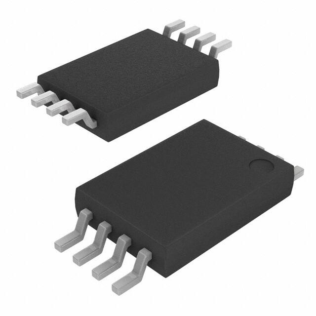
• 8-Lead PDIP, SOIC, and TSSOP Packages
• Available Temperature Ranges:
- Industrial (I):
-40°C to +85°C
- Automotive (E):
-40°C to +125°C
The
Microchip
Technology
Inc.
47L04/47C04/47L16/47C16 (47XXX) is a 4/16 Kbit
SRAM with EEPROM backup. The device is organized
as 512 x 8 bits or 2,048 x 8 bits of memory, and
utilizes the I2C serial interface. The 47XXX provides
infinite read and write cycles to the SRAM while
EEPROM cells provide high-endurance nonvolatile
storage of data. With an external capacitor, SRAM
data is automatically transferred to the EEPROM upon
loss of power. Data can also be transferred manually
by using either the Hardware Store pin or software
control. Upon power-up, the EEPROM data is
automatically recalled to the SRAM. Recall can also
be initiated through software control.
2015-2018 Microchip Technology Inc.
The 47XXX is available in the 8-lead PDIP, SOIC, and
TSSOP packages.
Package Types
PDIP/SOIC/TSSOP
(8-pin)
VCAP
1
8
VCC
A1
A2
2
3
7
6
HS
SCL
VSS
4
5
SDA
DS20005371D-page 1
�47L04/47C04/47L16/47C16
Typical Application Schematic Auto-Store Mode (ASE = 1)
VCC
VCC
VCC
8
VCC
VCAP
6
PIC® MCU
5
7
1
CVCAP
SCL
47XXX
SDA
HS
VSS
4
Typical Application Schematic Manual Store Mode (ASE = 0)
VCC
VCC
VCC
8
VCC
VCAP
6
®
PIC MCU
5
7
1
SCL
47XXX
SDA
HS
VSS
4
Block Diagram
VCC
VCAP
SDA
SCL
A2, A1
Power
Control
Block
I2C Control Logic
Slave Address
Decoder
Status Register
EEPROM
512 x 8
2K x 8
HS
Memory Address
and Data Control
Logic
DS20005371D-page 2
SRAM
512 x 8
2K x 8
STORE
RECALL
2015-2018 Microchip Technology Inc.
�47L04/47C04/47L16/47C16
1.0
ELECTRICAL CHARACTERISTICS
1.1
Absolute Maximum Ratings(†)
VCC.............................................................................................................................................................................6.5V
A1, A2, SDA, SCL, HS pins w.r.t. VSS .......................................................................................................... -0.6V to 6.5V
Storage temperature ...............................................................................................................................-65°C to +150°C
Ambient temperature under bias.............................................................................................................-40°C to +125°C
ESD protection on all pins........................................................................................................................................ ≥4 kV
† NOTICE: Stresses above those listed under ‘Absolute Maximum Ratings’ may cause permanent damage to the
device. This is a stress rating only and functional operation of the device at those or any other conditions above those
indicated in the operational listings of this specification is not implied. Exposure to maximum rating conditions for an
extended period of time may affect device reliability.
TABLE 1-1:
DC CHARACTERISTICS
47LXX:
47CXX:
Industrial (I):
Automotive (E):
DC CHARACTERISTICS
Param.
No.
Symbol
Characteristic
Min.
Typ.
VCC = 2.7V to 3.6V
VCC = 4.5V to 5.5V
TA = -40°C to +85°C
TA = -40°C to +125°C
Max.
Units
D1
VIH
High-Level Input Voltage
0.7VCC
—
VCC+1
V
D2
VIL
Low-Level Input Voltage
-0.3
—
0.3VCC
V
Low-Level Output Voltage
—
D3
VOL
D4
VHYS
D5
Conditions
—
0.4
V
IOL = 3.0 mA
Hysteresis of Schmitt
0.05VCC
Trigger Inputs (SDA, SCL
pins)
—
—
V
Note 1
ILI
Input Leakage Current
(SDA, SCL pins)
—
—
±1
µA
VIN = VSS or VCC
D6
ILO
Output Leakage Current
(SDA pin)
—
—
±1
µA
VOUT = VSS or VCC
D7
RIN
Input Resistance to VSS
(A1, A2, HS pins)
50
—
—
kΩ
VIN = VIL (max.)
750
—
—
kΩ
VIN = VIH (min.)
—
—
7
pF
TA = +25°C, FREQ = 1 MHz,
VCC = 5.5V (Note 1)
D8
CINT
D9
ICC Active
D10
D11
D12
ICC Recall
ICC Store
Internal Capacitance
(all inputs and outputs)
Operating Current
Recall Current (Note 2)
Manual Store Current
(Note 2)
ICC
Auto-Store Current
Auto-Store (Notes 1, 2 and 3)
—
200
400
µA
VCC = 5.5V, FCLK = 1 MHz
—
150
300
µA
VCC = 3.6V, FCLK = 1 MHZ
—
—
700
µA
VCC = 5.5V
—
300
500
µA
VCC = 3.6V
—
—
2500
µA
VCC = 5.5V
—
—
1500
µA
VCC = 3.6V
—
400
—
µA
VCC, VCAP = VTRIP (min.)
47CXX
—
300
—
µA
VCC, VCAP = VTRIP (min.)
47LXX
Note 1: This parameter is periodically sampled and not 100% tested.
2: Store and Recall currents are specified as an average current across the entire operation.
3: CVCAP required when Auto-Store is enabled (ASE = 1).
2015-2018 Microchip Technology Inc.
DS20005371D-page 3
�47L04/47C04/47L16/47C16
TABLE 1-1:
DC CHARACTERISTICS (CONTINUED)
47LXX:
47CXX:
Industrial (I):
Automotive (E):
DC CHARACTERISTICS
Param.
No.
D13
D14
D15
Symbol
ICC Status
Write
ICCS
VTRIP
D16
VPOR
D17
CB
D18
CVCAP
Characteristic
Status Write Current
Standby Current
Min.
Typ.
VCC = 2.7V to 3.6V
VCC = 4.5V to 5.5V
TA = -40°C to +85°C
TA = -40°C to +125°C
Max.
Units
Conditions
—
—
2500
µA
VCC = 5.5V
—
—
1500
µA
VCC = 3.6V
—
—
40
µA
SCL, SDA, VCAP, VCC = 5.5V
—
—
40
µA
SCL, SDA, VCAP, VCC = 3.6V
Auto-Store/Auto-Recall
Trip Voltage
4.0
—
4.4
V
47CXX
2.4
—
2.6
V
47LXX
Power-On Reset Voltage
—
1.1
—
V
Bus Capacitance
—
—
400
pF
Auto-Store Capacitance
(Notes 1 and 3)
3.5
4.7
—
µF
47C04
5
6.8
—
µF
47C16
5
6.8
—
µF
47L04
8
10
—
µF
47L16
Note 1: This parameter is periodically sampled and not 100% tested.
2: Store and Recall currents are specified as an average current across the entire operation.
3: CVCAP required when Auto-Store is enabled (ASE = 1).
DS20005371D-page 4
2015-2018 Microchip Technology Inc.
�47L04/47C04/47L16/47C16
TABLE 1-2:
AC CHARACTERISTICS
AC CHARACTERISTICS
Param.
No.
Symbol
VCC = 2.7V to 3.6V
VCC = 4.5V to 5.5V
TAMB = -40°C to +85°C
TAMB = -40°C to +125°C
47LXX:
47CXX:
Industrial (I):
Automotive (E):
Characteristic
Min.
Max.
Units
Conditions
1
FCLK
Clock Frequency
—
1000
kHz
2
THIGH
Clock High Time
500
—
ns
3
TLOW
Clock Low Time
500
—
ns
4
TR
SDA and SCL Input Rise
Time
—
300
ns
Note 1
5
TF
SDA and SCL Input Fall
Time
—
300
ns
Note 1
6
THD:STA
Start Condition Hold Time
250
—
ns
7
TSU:STA
Start Condition Setup
Time
250
—
ns
8
THD:DAT
Data Input Hold Time
0
—
ns
9
TSU:DAT
Data Input Setup Time
100
—
ns
10
TSU:STO
Stop Condition Setup
Time
250
—
ns
11
TAA
—
400
ns
12
TBUF
Bus Free Time: Bus time
must be free before a new
transmission can start
500
—
ns
13
TSP
Input Filter Spike
Suppression (SDA, SCL
and HS pins)
—
50
ns
14
THSPW
150
—
ns
15
TRECALL
—
5
ms
47X16
—
2
ms
47X04
—
25
ms
47X16
—
8
ms
47X04
—
1
ms
16
17
TSTORE
TWC
Output Valid from Clock
Hardware Store Pulse
Width
Recall Operation Duration
Store Operation Duration
STATUS Register Write
Cycle Time
Note 1
18
TVRISE
VCC Rise Rate
70
—
µs/V
Note 1
19
TvFALL
VCC Fall Rate
70
—
µs/V
Note 1
1,000,000
—
Store
cycles
20
EEPROM Endurance
+25°C, VCC = 5.5V
(Notes 1 and 2)
Note 1: This parameter is not tested but ensured by characterization.
2: For endurance estimates in a specific application, please consult the Total Endurance Model which can
be obtained on Microchip’s website at www.microchip.com.
2015-2018 Microchip Technology Inc.
DS20005371D-page 5
�47L04/47C04/47L16/47C16
FIGURE 1-1:
BUS TIMING DATA
SCL
7
3
SDA
IN
D4
2
5
8
4
10
9
6
13
12
11
SDA
OUT
FIGURE 1-2:
AUTO-STORE/AUTO-RECALL TIMING DATA
D15
VCAP
D16
16
16
Auto-Store
15
Auto-Recall
Device Access
Enabled
FIGURE 1-3:
HARDWARE STORE TIMING DATA (WITH AM = 1)
14
HS Pin
16
Hardware Store
Operation
17
STATUS Register
Write Cycle
Device Access
Enabled
DS20005371D-page 6
2015-2018 Microchip Technology Inc.
�47L04/47C04/47L16/47C16
FIGURE 1-4:
HARDWARE STORE TIMING DATA (WITH AM = 0)
14
HS Pin
17
STATUS Register
Write Cycle
Device Access
Enabled
2015-2018 Microchip Technology Inc.
DS20005371D-page 7
�47L04/47C04/47L16/47C16
2.0
FUNCTIONAL DESCRIPTION
2.0.1
PRINCIPLES OF OPERATION
The 47XXX is a 4/16 Kbit serial EERAM designed to
support a bidirectional two-wire bus and data
transmission protocol (I2C). A device that sends data
onto the bus is defined as transmitter, and a device
receiving data is defined as receiver. The bus has to
be controlled by a master device which generates the
Start and Stop conditions, while the 47XXX works as
slave. Both master and slave can operate as
transmitter or receiver, but the master device
determines which mode is active.
2.1
Bus Characteristics
2.1.1
SERIAL INTERFACE
2.1.1.3
Stop Data Transfer (C)
A low-to-high transition of the SDA line while the clock
(SCL) is high determines a Stop condition. All
operations must end with a Stop condition.
2.1.1.4
Data Valid (D)
The state of the data line represents valid data when,
after a Start condition, the data line is stable for the
duration of the high period of the clock signal.
The data on the line must be changed during the low
period of the clock signal. There is one bit of data per
clock pulse.
Each data transfer is initiated with a Start condition and
terminated with a Stop condition. The number of the
data bytes transferred between the Start and Stop conditions is determined by the master device.
The following bus protocol has been defined:
2.1.1.5
• Data transfer may be initiated only when the bus
is not busy.
• During data transfer, the data line must remain
stable whenever the clock line is high. Changes in
the data line while the clock line is high will be
interpreted as a Start or Stop condition.
Each receiving device, when addressed, is obliged to
generate an Acknowledge signal after the reception of
each byte. The master device must generate an extra
clock pulse which is associated with this Acknowledge
bit.
Accordingly, the following bus conditions have been
defined (Figure 2-1).
2.1.1.1
Bus Not Busy (A)
Both data and clock lines remain high.
2.1.1.2
Start Data Transfer (B)
A high-to-low transition of the SDA line while the clock
(SCL) is high determines a Start condition. All
commands must be preceded by a Start condition.
FIGURE 2-1:
(A)
Acknowledge
A device that Acknowledges must pull down the SDA
line during the Acknowledge clock pulse in such a way
that the SDA line is stable low during the high period of
the Acknowledge related clock pulse. Of course, setup
and hold times must be taken into account. During
reads, a master must signal an end of data to the slave
by NOT generating an Acknowledge bit on the last byte
that has been clocked out of the slave. In this case, the
slave (47XXX) will leave the data line high to enable the
master to generate the Stop Condition.
There are situations where the 47XXX will NOT
generate an Acknowledge bit in order to signal that an
error has occurred. Table 2-1 and Table 2-2 summarize
these situations.
DATA TRANSFER SEQUENCE ON THE SERIAL BUS
(B)
(D)
Start
Condition
Address or
Acknowledge
Valid
(D)
(C)
(A)
SCL
SDA
DS20005371D-page 8
Data
Allowed
to Change
Stop
Condition
2015-2018 Microchip Technology Inc.
�47L04/47C04/47L16/47C16
FIGURE 2-2:
ACKNOWLEDGE TIMING
Acknowledge
Bit
SCL
1
2
SDA
3
4
5
6
7
8
9
2
3
Data from transmitter
Data from transmitter
Receiver must release the SDA line at this point
so the Transmitter can continue sending data.
Transmitter must release the SDA line at this point
allowing the Receiver to pull the SDA line low to
acknowledge the previous eight bits of data.
TABLE 2-1:
1
ACKNOWLEDGE TABLE FOR SRAM WRITES
ACK
Address
MSB
ACK
Address
LSB
SRAM Write in Unprotected Block
ACK
Address
ACK
Address
ACK
Data
ACK
SRAM Write in Protected Block
ACK
Address
ACK
Address
ACK
Data
NoACK
Instruction
TABLE 2-2:
Data
Byte
ACK
ACK
ACKNOWLEDGE TABLE FOR CONTROL REGISTER WRITES
Instruction
ACK
Address
ACK
Data Byte
ACK
STATUS Register Write
ACK
00h
ACK
Data
ACK
Software Store Command
ACK
55h
ACK
33h
ACK
Software Recall Command
ACK
55h
ACK
DDh
ACK
Write Invalid Value to COMMAND Register
ACK
55h
ACK
Invalid Command
NoACK
Write to Invalid Register Address
ACK
Invalid Address
NoACK
Don’t Care
NoACK
2015-2018 Microchip Technology Inc.
DS20005371D-page 9
�47L04/47C04/47L16/47C16
2.2
Device Addressing
The control byte is the first byte received following the
Start condition from the master device (Figure 2-3).
The control byte begins with a 4-bit operation code.
The next two bits are the user-configurable Chip
Select bits: A2 and A1. The next bit is a non-configurable Chip Select bit that must always be set to ‘0’.
The Chip Select bits A2 and A1 in the control byte
must match the logic levels on the corresponding A2
and A1 pins for the device to respond.
The last bit of the control byte defines the operation to
be performed. When set to a ‘1’ a read operation is
selected, and when set to a ‘0’ a write operation is
selected.
The combination of the 4-bit operation code and the
three Chip Select bits is called the slave address.
Upon receiving a valid slave address, the slave device
outputs an acknowledge signal on the SDA line.
Depending on the state of the R/W bit, the 47XXX will
select a read or a write operation.
The 47XXX is divided into two functional units: the
SRAM array and the Control registers. Section 2.3
“SRAM Array” describes the functionality for the
SRAM array and Section 2.4 “Control Registers”
describes the Control registers.
The 4-bit op code in the control byte determines which
unit will be accessed during an operation. Table 2-3
shows the standard control bytes used by the 47XXX.
TABLE 2-3:
CONTROL BYTES
Op
Code
Chip
Select
R/W
Bit
SRAM Read
1010
A2 A1 0
1
SRAM Write
1010
A2 A1 0
0
Control Register Read
0011
A2 A1 0
1
Control Register Write
0011
A2 A1 0
0
Operation
Note: When VCAP is below VTRIP, the 47XXX
cannot be accessed and will not
acknowledge any commands.
FIGURE 2-3:
CONTROL BYTE FORMAT
Acknowledge Bit
Read/Write Bit
Start Bit
Chip Select
Bits
Op Code
S
1
0
1
0
A2
A1
0
R/W ACK
A1
0
R/W ACK
OR
S
0
0
1
1
A2
Slave Address
DS20005371D-page 10
2015-2018 Microchip Technology Inc.
�47L04/47C04/47L16/47C16
2.3
2.3.1.1
SRAM Array
The SRAM array is the only directly-accessible
memory on the 47XXX. The EEPROM array provides
nonvolatile storage to back up the SRAM data.
To select the SRAM array, the master device must use
the respective 4-bit op code ‘1010’ when transmitting
the control byte.
Note: If an Auto-Store or Hardware Store is
triggered during an SRAM read or write
operation, the operation is aborted in
order to execute the Store.
2.3.1
After the 47XXX has received the 2-byte array
address, responding with an Acknowledge after each
address byte, the master device will transmit the data
byte to be written into the addressed memory location.
The 47XXX acknowledges again, and the master
generates a Stop condition (Figure 2-4). The data byte
is latched into the SRAM array on the rising edge of
SCL during the Acknowledge.
After a byte Write command, the internal Address
Pointer will point to the address location following the
location that was just written.
WRITE OPERATION
2.3.1.2
When the SRAM array is selected and the R/W bit in
the control byte is set to ‘0’, a write operation is
selected and the next two bytes received are
interpreted as the array address. The Most Significant
address bits are transferred first, followed by the less
significant bits, and are shifted directly into the internal
Address Pointer. The Address Pointer determines
where in the SRAM array the next read or write
operation begins.
Data bytes are stored into the SRAM array as soon as
each byte is received, specifically on the rising edge of
SCL during each Acknowledge bit. If a write operation
is aborted for any reason, all received data will already
be stored in SRAM, except for the last data byte if the
rising edge of SCL during the Acknowledge for that
byte has not yet been reached.
Note: If an attempt is made to write to a protected portion of the array, the device
will not respond with an Acknowledge
after the data byte is received, the current operation will be terminated without
incrementing the Address Pointer, and
any data transmitted on the SDA line will
be ignored until a new operation is
begun with a Start condition.
FIGURE 2-4:
Byte Write
Sequential Write
To write multiple data bytes in a single operation, the
SRAM write control byte, array address, and the first
data byte are transmitted to the 47XXX in the same
way as for a byte write. However, instead of
generating a Stop condition, the master transmits
additional data bytes (Figure 2-5). Upon receipt of
each byte, the 47XXX responds with an Acknowledge:
during which the data is latched into the SRAM array
on the rising edge of SCL, and the Address Pointer is
incremented by one. Sequential write operations are
limited only by the size of the SRAM array, and if the
master should transmit enough bytes to reach the end
of the array, the Address Pointer will roll over to 0x000
and continue writing. There is no limit to the number of
bytes that can be written in a single command.
Note: If a sequential write crosses into a protected block, the device will not respond
with an Acknowledge after the data byte
is received, the current operation will be
terminated without incrementing the
Address Pointer, and any data transmitted on the SDA line will be ignored until
a new operation is begun with a Start
condition.
SRAM BYTE WRITE
Bus Activity
Master
SDA Line
S
T
A
R
T
Control
Byte
Address
High Byte
A
S1 0 10A
2 1 00
Bus Activity
Address
Low Byte
S
T
O
P
Data
P
XXXXXYY
A
C
K
A
C
K
A
C
K
A
C
K
Data Latched
into SRAM
X = Don’t Care
Y = Don’t Care for 47X04
2015-2018 Microchip Technology Inc.
DS20005371D-page 11
�47L04/47C04/47L16/47C16
FIGURE 2-5:
Bus Activity
Master
SDA Line
SRAM SEQUENTIAL WRITE
S
T
A
R
T
Control
Byte
Address
High Byte
AA
S101 02 100
Bus Activity
Address
Low Byte
S
T
O
P
Data Byte N
Data Byte 0
P
X XX X X Y Y
A
C
K
A
C
K
A
C
K
A
C
K
A
C
K
Data Latched
into SRAM
X = Don’t Care
Y = Don’t Care for 47X04
DS20005371D-page 12
2015-2018 Microchip Technology Inc.
�47L04/47C04/47L16/47C16
2.3.2
2.3.2.2
READ OPERATION
When the SRAM array is selected and the R/W bit is
set to ‘1’, a read operation is selected. For read operations, the array address is not transmitted. Instead, the
internal Address Pointer is used to determine where
the read starts.
Random read operations allow the master to access
any memory location in a random manner. To perform
this type of read operation, first the Address Pointer
must be set. This is done by sending the array address
to the 47XXX as part of a write operation (R/W bit set
to ‘0’). After the array address is sent, the master
generates
a
Start
condition
following
the
Acknowledge. This terminates the write operation, but
not before the Address Pointer has been set. Then,
the master issues the SRAM control byte again, but
with the R/W bit set to a ‘1’. The 47XXX will then issue
an Acknowledge and transmit the 8-bit data byte. The
master will not Acknowledge the transfer but does
generate a Stop condition, which causes the 47XXX to
discontinue transmission (Figure 2-7). After a random
read operation, the Address Pointer will point to the
address location following the one that was just read.
During read operations, the master device generates
the Acknowledge bit after each data byte, and it is this
bit which determines whether the operation will continue or end. A ‘0’ (Acknowledge) bit requests more
data and continues the read, while a ‘1’ (No Acknowledge) bit ends the read operation.
2.3.2.1
Current Address Read
The current address read operation relies on the
current value of the Address Pointer to determine from
where to start reading. The Address Pointer is
automatically incremented after each data byte is read
or written. Therefore, if the previous access was to
address ‘n’ (where ‘n’ is any legal address), the next
current address read operation would access data
beginning with address ‘n+1’.
2.3.2.3
SRAM CURRENT
ADDRESS READ
Bus Activity
Master
S
T
A
R
T
SDA Line
S 10 10 A A 0 1
2 1
Control
Byte
FIGURE 2-7:
Bus Activity
Master
SDA Line
P
A
C
K
Bus Activity
S
T
O
P
Data
Byte
Sequential Read
Sequential reads are initiated in the same way as a
random read, except that after the 47XXX transmits
the first data byte, the master issues an Acknowledge
as opposed to the Stop condition used in a random
read. The Acknowledge directs the 47XXX to transmit
the next sequentially addressed 8-bit byte
(Figure 2-8). Following the final byte transmitted to the
master, the master will NOT generate an Acknowledge
but will generate a Stop condition. To provide sequential reads, the 47XXX increments the internal Address
Pointer by one after the transfer of each data byte.
This allows the entire memory contents to be serially
read during one operation. The Address Pointer will
automatically roll over at the end of the array to
address 0x000 after the last data byte in the array has
been transferred.
Upon receipt of the control byte with the R/W bit set to
‘1’, the 47XXX issues an Acknowledge and transmits
the 8-bit data byte. The master will not acknowledge
the transfer, but does generate a Stop condition and
the 47XXX discontinues transmission (Figure 2-6).
FIGURE 2-6:
Random Read
N
O
A
C
K
SRAM RANDOM READ
S
T
A
R
T
Control
Byte
Address
High Byte
S1 0 1 0 AA00
2 1
Bus Activity
X = Don’t Care
Y = Don’t Care for 47X04
2015-2018 Microchip Technology Inc.
S
T
A
R
T
Address
Low Byte
XXXXXYY
A
C
K
A
C
K
A
C
K
Control
Byte
S 1 0 1 0 A A0 1
2 1
S
T
O
P
Data
Byte
P
A
C
K
N
O
A
C
K
DS20005371D-page 13
�47L04/47C04/47L16/47C16
FIGURE 2-8:
Bus Activity
Master
SRAM SEQUENTIAL READ
Control
Byte
DATA n
DATA n + 1
P
SDA Line
Bus Activity
DS20005371D-page 14
S
T
O
P
DATA n + X
DATA n + 2
A
C
K
A
C
K
A
C
K
A
C
K
N
O
A
C
K
2015-2018 Microchip Technology Inc.
�47L04/47C04/47L16/47C16
2.4
Table 2-4 lists the available Control registers. The
STATUS register allows the user to configure the
47XXX. The COMMAND register is used to execute
special Software commands.
Control Registers
To support device configuration features such as
software
write
protection,
as
well
as
software-controllable Store and Recall operations, the
47XXX features a set of Control registers that are
accessed using a different 4-bit op code than the op
code for the SRAM array (refer to Table 2-3 for op
code values).
Note: The COMMAND register is write-only.
Note: If an Auto-Store or Hardware Store is
triggered during a Control register read
or write operation, the operation is
aborted in order to execute the Store.
TABLE 2-4:
Register Name
CONTROL REGISTERS
Address
Bit 7
Bit 6
Bit 5
Bit 4
Bit 3
Bit 2
Bit 1
Bit 0
STATUS
00h
AM
—
—
BP2
BP1
BP0
ASE
EVENT
COMMAND
55h
CMD7
CMD6
CMD5
CMD4
CMD3
CMD2
CMD1
CMD0
2.4.1
STATUS REGISTER
The STATUS register controls the software write
protection, enables/disables the Auto-Store function,
reports whether or not the array has been modified
since the last Store or Recall operation, and contains
the Hardware Store event flag.
There are several bits contained within the STATUS
register:
• The AM bit indicates whether or not the SRAM
array has been written to since the last Store or
Recall operation. When set to a ‘0’, the SRAM
array matches the data in the EEPROM array.
When set to a ‘1’, the SRAM array no longer
matches the EEPROM array. The AM bit is set
whenever a data byte is written to the SRAM, and
is cleared after a Store or Recall operation is
completed. The AM bit must be a ‘1’ to enable the
Auto-Store and Hardware Store functions.
However, the Software Store command is always
enabled. The AM bit is volatile and is read-only.
• The BP bits control the SRAM array software
write protection. Table 2-5 lists the address
ranges that can be protected for each device. The
BP bits are nonvolatile.
• The ASE bit determines whether or not the
Auto-Store function is enabled. When set to a ‘1’,
the Auto-Store function is enabled and will execute automatically on power-down if the array has
been modified. When set to a ‘0’, the Auto-Store
function is disabled. The ASE bit is nonvolatile.
• The EVENT bit indicates whether or not an external event has been detected on the HS pin. When
the HS pin is driven high, a STATUS register write
operation is automatically initiated following the
Hardware Store operation to set this bit to a ‘1’.
This bit can also be set and cleared through a
STATUS register Write command. The EVENT bit
is nonvolatile.
Note: The HS pin is ignored when VCAP is
below VTRIP, and during Store and
Recall operations. In these cases, the
EVENT bit will not be written.
To store the nonvolatile bits in the STATUS register, a
write cycle occurs after a STATUS register write
operation, during which the 47XXX cannot be
accessed for TWC time after the Stop condition.
Note:
During a STATUS register write cycle, an
Auto-Store or Hardware Store can still be
triggered, but the Store operation will not
execute until the STATUS register write
cycle is complete (Figure 2-13). In this
situation, the new value of the ASE bit will
be used to determine if the Auto-Store is
executed.
Note: If a capacitor is not connected to the
VCAP pin, then the VCAP pin must be
connected to VCC and the Auto-Store
feature must be disabled by writing the
ASE bit to a ‘0’ to prevent data corruption in the EEPROM array when power
is lost.
2015-2018 Microchip Technology Inc.
DS20005371D-page 15
�47L04/47C04/47L16/47C16
TABLE 2-5:
PROTECTED ARRAY ADDRESS LOCATIONS
Protected
Range
BP2
BP1
BP0
47X04
47X16
None
0
0
0
—
—
Upper 1/64
0
0
1
1F8h-1FFh
7E0h-7FFh
Upper 1/32
0
1
0
1F0h-1FFh
7C0h-7FFh
Upper 1/16
0
1
1
1E0h-1FFh
780h-7FFh
Upper 1/8
1
0
0
1C0h-1FFh
700h-7FFh
Upper 1/4
1
0
1
180h-1FFh
600h-7FFh
Upper 1/2
1
1
0
100h-1FFh
400h-7FFh
All Blocks
1
1
1
000h-1FFh
000h-7FFh
REGISTER 2-1:
STATUS REGISTER
R-0
U-0
U-0
R/W
R/W
R/W
R/W
R/W
AM
—
—
BP2
BP1
BP0
ASE
EVENT
bit 7
bit 0
Legend:
R = Readable bit
W = Writable bit
U = Unimplemented bit, read as ‘0’
-n = Value at POR
‘1’ = Bit is set
‘0’ = Bit is cleared
bit 7
AM: Array Modified bit
1 = SRAM array has been modified
0 = SRAM array has not been modified
bit 6-5
Unimplemented: Read as ‘0’
bit 4-2
BP: Block Protect bits
000 = Entire array is unprotected
001 = Upper 1/64 of array is write-protected
010 = Upper 1/32 of array is write-protected
011 = Upper 1/16 of array is write-protected
100 = Upper 1/8 of array is write-protected
101 = Upper 1/4 of array is write-protected
110 = Upper 1/2 of array is write-protected
111 = Entire array is write-protected
bit 1
ASE: Auto-Store Enable bit
1 = Auto-Store feature is enabled
0 = Auto-Store feature is disabled
bit 0
EVENT: Event Detect bit
1 = An event was detected on the HS pin
0 = No event was detected on the HS pin
DS20005371D-page 16
x = Bit is unknown
2015-2018 Microchip Technology Inc.
�47L04/47C04/47L16/47C16
2.4.2
COMMAND REGISTER
The COMMAND register is a write-only register that
allows the user to execute software-controlled Store
and Recall operations. There are two commands that
can be executed, as shown in Table 2-6:
• The Software Store command initiates a manual
Store operation. The 47XXX cannot be accessed
for TSTORE time after this command has been
received. During this time, the 47XXX will not
acknowledge any communication. The Software
Store command will execute regardless of the
state of the AM and ASE bits in the STATUS
register. The AM bit will be cleared at the end of
the Store operation.
• The Software Recall command initiates a manual
Recall operation. The 47XXX cannot be accessed
for TRECALL time after this command has been
received.
REGISTER 2-2:
During this time, the 47XXX will not acknowledge
any communication. The AM bit will be cleared at
the end of the Recall operation.
Note: If a capacitor is not connected to the
VCAP pin, then the VCAP pin must be
connected to VCC and the user must
ensure that power is not lost during a
Store operation, otherwise data corruption may occur.
TABLE 2-6:
COMMAND SET
Command
Value
Description
Software
Store
0011 0011 Store SRAM data to
EEPROM
Software
Recall
1101 1101 Recall data from
EEPROM to SRAM
COMMAND REGISTER
W
W
W
W
W
W
W
W
CMD7
CMD6
CMD5
CMD4
CMD3
CMD2
CMD1
CMD0
bit 7
bit 0
Legend:
R = Readable bit
W = Writable bit
U = Unimplemented bit, read as ‘0’
-n = Value at POR
‘1’ = Bit is set
‘0’ = Bit is cleared
bit 7-0
x = Bit is unknown
CMD: Command bits
00110011 = Executes a Software Store command
11011101 = Executes a Software Recall command
2015-2018 Microchip Technology Inc.
DS20005371D-page 17
�47L04/47C04/47L16/47C16
2.4.3
CONTROL REGISTER WRITE
OPERATION
If the data byte is valid, the 47XXX acknowledges
again and the master generates a Stop condition.
For a STATUS register write operation, any data byte
value is valid. However, for COMMAND register write
operations, only the commands listed in Table 2-6 are
valid. If a different command value is received, the
47XXX will not acknowledge the command, the
current operation will be terminated, and any data
transmitted on the SDA line will be ignored until a new
operation is begun with a Start condition.
When the Control registers are selected and the R/W
bit in the control byte is set to ‘0’, a write operation is
selected and the next byte received is interpreted as
the register address. The Most Significant address bits
are transferred first, followed by the less significant
bits. The register address is decoded as soon as it is
received and has no effect on future operations.
The register address must be a valid Control register
address listed in Table 2-4, otherwise the 47XXX will
not acknowledge the address, the current operation
will be terminated, and any data transmitted on the
SDA line will be ignored until a new operation is begun
with a Start condition.
Note 1: When writing to the COMMAND register,
the master must send exactly one data
byte. If additional data bytes are sent,
then the 47XXX will not acknowledge the
data bytes and will abort the operation.
2: Multiple data bytes are allowed when
writing to the STATUS register. The last
data byte received will be written.
After receiving the Acknowledge signal from the
47XXX following the register address, the master will
transmit the data byte to be written to the addressed
register.
FIGURE 2-9:
CONTROL REGISTER WRITE
Bus Activity
Master
SDA Line
S
T
A
R
T
Control
Byte
2.4.4
S
T
O
P
Data
A
S0 01 1A
2 100
Bus Activity
Note 1:
Address
Byte
P
A
C
K
A
C
K
A
C
K
TWC(1)
TSTORE(1)
TRECALL(1)
After the Stop condition, a delay must be observed for the command to execute: TWC for STATUS register writes,
TSTORE for Software Store commands, and TRECALL for Software Recall commands.
CONTROL REGISTER READ
OPERATION
When the Control registers are selected and the R/W
bit in the control byte is set to ‘1’, a read operation is
selected. For read operations, the register address is
not transmitted. Since the COMMAND register is
write-only, all Control register read operations access
the STATUS register.
During read operations, the master device generates
the Acknowledge bit after each data byte, and it is this
bit which determines whether the operation will continue or end. A ‘0’ (Acknowledge) bit requests more
data and continues the read, while a ‘1’ (No Acknowledge) bit ends the read operation.
Upon receipt of the control byte with the R/W bit set to
‘1’, the 47XXX issues an Acknowledge and transmits
the 8-bit STATUS register value. The master will not
acknowledge the transfer, but does generate a Stop
condition and the 47XXX discontinues transmission
(Figure 2-10).
DS20005371D-page 18
FIGURE 2-10:
CONTROL REGISTER
READ
Bus Activity
Master
S
T
A
R
T
SDA Line
S 00 11 A A 0 1
2 1
Bus Activity
STATUS
Register
Byte
Control
Byte
S
T
O
P
P
A
C
K
N
O
A
C
K
Note: If the master acknowledges the data
byte, the 47XXX will retransmit the 8-bit
STATUS register value.
2015-2018 Microchip Technology Inc.
�47L04/47C04/47L16/47C16
2.5
STORE/RECALL OPERATIONS
In order to provide nonvolatile storage of the SRAM
data, an EEPROM array is included on the 47XXX.
The EEPROM array is not directly accessible to the
user. Instead, data is written to and read from the
EEPROM array using the various Store and Recall
operations, respectively.
To provide design flexibility for the user, the 47XXX
can automatically perform Store and Recall operations
on power-down and power-up, respectively, and also
offers Software commands and a Hardware Store pin
for manual control.
Refer to Section 2.4.2 “Command Register” for
details of the Software Store and Software Recall
commands.
Note:
2.5.1
If the AM bit is a ‘1’, the Hardware Store is initiated on
the rising edge of the HS pin, and then the 47XXX
cannot be accessed for (TSTORE + TWC) time. If the AM
bit is a ‘0’, only the EVENT bit write is initiated on the
rising edge of the HS pin, and then the 47XXX cannot
be accessed for TWC time while the STATUS register
is written.
The AM bit in the STATUS register is cleared at the
completion of the Hardware Store operation.
Note 1: The HS pin is ignored during Store and
Recall operations, or if VCAP is below
VTRIP.
2: The HS pin is triggered on the rising
edge. If the HS pin remains high after the
Hardware Store and STATUS register
write are complete, the device can still be
accessed normally just as if the HS pin
were low. Initiating a subsequent Hardware Store operation requires toggling
HS low then high again.
Once a Store operation is initiated, it
cannot be aborted.
AUTO-STORE
To simplify device usage, the 47XXX features an
Auto-Store mechanism. To enable this feature, the user
must place a capacitor on the VCAP pin and ensure the
ASE bit in the STATUS register is set to ‘1’. The
capacitor is charged through the VCC pin. When the
47XXX detects a power-down event, the device
automatically switches to the capacitor for power and
initiates the Auto-Store operation.
The Auto-Store is initiated when VCAP falls below
VTRIP. Even if power is restored, the 47XXX cannot be
accessed for TSTORE time after the Auto-Store is initiated.
To avoid extraneous Store operations, the Auto-Store
will only be initiated if the AM bit in the STATUS register
is set to a ‘1’, indicating the SRAM array has been
modified since the last Store or Recall operation.
The AM bit in the STATUS register is cleared at the
completion of the Auto-Store operation.
2.5.2
Driving the HS pin high will also automatically initiate a
STATUS register write cycle to write the EVENT bit to
a ‘1’, regardless of the state of the AM bit.
2.5.3
The AM bit in the STATUS register is cleared at the
completion of the Auto-Recall operation.
Note 1: If power is lost during an Auto-Recall
operation, the Auto-Recall is aborted and
the Auto-Store is not performed.
2: Auto-Recall is only performed the first
time VCAP rises above VTRIP after a POR
event. However, SRAM data will be
retained as long as Vcc remains above
VPOR.
HARDWARE STORE
The HS pin provides a method for manually initiating a
Store operation through an external trigger. Driving the
HS pin high for a minimum of THSPW time will initiate a
Hardware Store operation if the AM bit in the STATUS
register is a ‘1’.
TABLE 2-7:
AUTO-RECALL
The 47XXX features an Auto-Recall mechanism that is
performed on power-up, regardless of the state of the
ASE bit. This feature ensures that the SRAM data
duplicates the EEPROM data on power-up. The
Auto-Recall is only initiated the first time VCAP rises
above VTRIP after a POR event, and the 47XXX cannot be accessed for TRECALL time after the Auto-Recall
is initiated.
STORE ENABLE TRUTH TABLE
ASE Bit
AM Bit
Auto-Store
Enabled
Hardware Store
Enabled
Software Store
Enabled
Auto-Recall
Enabled
Software Recall
Enabled
x
0
No
No
Yes
Yes
Yes
0
1
No
Yes
Yes
Yes
Yes
1
1
Yes
Yes
Yes
Yes
Yes
2015-2018 Microchip Technology Inc.
DS20005371D-page 19
�47L04/47C04/47L16/47C16
FIGURE 2-11:
AUTO-STORE/AUTO-RECALL SCENARIOS (WITH ASE = 1, AM = 1)
VCC
VCAP
VTRIP
VPOR
Auto-Store
Auto-Recall
TSTORE
TRECALL
Device Access
Enabled
Array Modified
Bit
VCC
VCAP
Auto-Store
VTRIP
VPOR
TSTORE
Auto-Recall
Device Access
Enabled
Array Modified
Bit
VCC
VCAP
Auto-Store
VTRIP
VPOR
TSTORE
Auto-Recall
TRECALL
Device Access
Enabled
Array Modified
Bit
DS20005371D-page 20
2015-2018 Microchip Technology Inc.
�47L04/47C04/47L16/47C16
FIGURE 2-12:
AUTO-STORE/AUTO-RECALL SCENARIOS (WITH ASE = 0 OR AM = 0)
VCC
VCAP
VTRIP
VPOR
Auto-Store
Auto-Recall
Device Access
Enabled
Array Modified Bit
VCC
VCAP
VTRIP
VPOR
Auto-Store
Auto-Recall
TRECALL
Device Access
Enabled
Array Modified Bit
2015-2018 Microchip Technology Inc.
DS20005371D-page 21
�47L04/47C04/47L16/47C16
FIGURE 2-13:
STORE DURING STATUS REGISTER WRITE CYCLE SCENARIOS (WITH AM = 1)
VCC
VCAP
VTRIP
VPOR
STATUS Register
Write Cycle
TWC
Auto-Store
TSTORE(1)
Auto-Recall
Device Access
Enabled
Array Modified
Bit
HS
STATUS Register
Write Cycle
TWC(2)
TWC
Hardware Store
TSTORE
Device Access
Enabled
Array Modified Bit
Note 1:
Store operation will only execute if ASE bit = 1.
2: The second STATUS register write cycle is performed to set the EVENT bit to a ‘1’.
DS20005371D-page 22
2015-2018 Microchip Technology Inc.
�47L04/47C04/47L16/47C16
FIGURE 2-14:
STORE DURING STATUS REGISTER WRITE CYCLE SCENARIOS (WITH AM = 0)
VCC
VCAP
STATUS Register
Write Cycle
VTRIP
VPOR
TWC
Auto-Store
Auto-Recall
Device Access
Enabled
Array Modified
Bit
HS
STATUS Register
Write Cycle
TWC
TWC(1)
Hardware Store
Device Access
Enabled
Array Modified Bit
Note 1:
The second STATUS register write cycle is performed to set the EVENT bit to a ‘1’.
2015-2018 Microchip Technology Inc.
DS20005371D-page 23
�47L04/47C04/47L16/47C16
2.6
ACKNOWLEDGE POLLING
Since the device will not acknowledge during Store and
Recall operations, nor during the internal STATUS
register write cycles, checking for the Acknowledge
signal can be used to determine when those events are
complete. Once such an event has started,
Acknowledge polling can be initiated immediately. This
involves the master sending a Start condition, followed
by the write control byte (R/W = 0) for either the SRAM
array or the Control registers. If the device is still busy,
then no Acknowledge will be returned. In this case,
then the Start condition and control byte must be
resent. If the Store or Recall is complete, then the
device will return an Acknowledge, and the master can
then proceed with the next Read or Write command.
See Figure 2-15 for flow diagram.
FIGURE 2-15:
ACKNOWLEDGE
POLLING FLOW
Initiate
Store, Recall, or
STATUS Register Write Event
Send Start
Send Control Byte
with R/W = 0
Did Device
Acknowledge
(ACK = 0)?
NO
YES
Next
Operation
Note:
Either the SRAM or Control register
control byte can be used for Acknowledge Polling
DS20005371D-page 24
2015-2018 Microchip Technology Inc.
�47L04/47C04/47L16/47C16
The descriptions of the pins are listed in Table 3-1.
For normal data transfer SDA is allowed to change only
during SCL low. Changes during SCL high are
reserved for indicating the Start and Stop conditions.
TABLE 3-1:
3.1.4
3.0
PIN DESCRIPTIONS
Name
PIN FUNCTION TABLE
8-pin
PDIP
SOIC
TSSOP
Function
3.1.5
VCAP
1
Capacitor Input
A1
2
Chip Select Input
A2
3
Chip Select Input
VSS
4
Ground
SDA
5
Serial Data
SCL
6
Serial Clock
HS
7
Hardware Store/
Event Detect Input
VCC
8
Power Supply
3.1
3.1.1
HARDWARE STORE/EVENT
DETECT (HS)
This pin is used to initiate a Hardware Store operation
by driving the pin high for THSPW time. This will also
trigger a STATUS register write cycle to write the
EVENT bit to a ‘1’.
This pin is ignored during Store and Recall operations,
or if VCAP is below VTRIP. If the AM bit in the STATUS
register is set to a ‘0’, the Hardware Store will not be
initiated, but the EVENT bit will still be written to a ‘1’.
If left unconnected, this input will be pulled down
internally to VSS.
Pin Descriptions
CAPACITOR INPUT (VCAP)
The VCAP pin is connected to the internal power bus of
the 47XXX.
If the Auto-Store feature is used, a CVCAP capacitor
must be connected to the VCAP pin in order to store
the energy required to complete the Auto-Store
operation on power-down. The capacitor is
automatically charged through VCC. See Table 1-1 for
recommended CVCAP values.
If a capacitor is not connected to the VCAP pin, then
the VCAP pin must be connected to the VCC pin and
the Auto-Store feature must be disabled by writing the
ASE bit in the STATUS register to a ‘0’ to prevent data
corruption in the EEPROM array when power is lost.
3.1.2
SERIAL CLOCK (SCL)
This input is used to synchronize the data transfer from
and to the device.
CHIP ADDRESS INPUTS (A1, A2)
3.2
Input Pull-down Circuitry
The A1, A2, and HS pins are internally pulled down to
VSS using dual-strength pull-down circuits. Figure 3-1
shows the block diagram of the circuit.
The circuit is designed to have a relatively strong
pull-down strength when the input voltage is below VIL,
and a much weaker pull-down when the input is above
VIH.
See Table 1-1 for actual resistance values.
FIGURE 3-1:
PULL-DOWN CIRCUIT
BLOCK DIAGRAM
I/O PIN
The A1, A2 inputs are used by the 47XXX for multiple
device operation. The levels on these inputs are
compared with the corresponding Chip Select bits in
the slave address. The chip is selected if the
comparison is true.
Up to four devices may be connected to the same bus
by using different Chip Select bit combinations. If left
unconnected, these inputs will be pulled down
internally to VSS.
3.1.3
SERIAL DATA (SDA)
This is a bidirectional pin used to transfer addresses
and data into and data out of the device. It is an
open-drain terminal, therefore, the SDA bus requires a
pull-up resistor to VCC (typical 10 kΩ for 100 kHz, 2 kΩ
for 400 kHz and 1 MHz).
2015-2018 Microchip Technology Inc.
DS20005371D-page 25
�47L04/47C04/47L16/47C16
4.0
PACKAGING INFORMATION
4.1
Package Marking Information
8-Lead PDIP (300 mil)
Example
47C04
P e3 017
1621
8-Lead SOIC (3.90 mm)
Example
47L16
SN e3 1621
017
8-Lead TSSOP
Example
AAAT
1621
017
1st Line Marking Codes
Part Number
PDIP
e3
Note:
DS20005371D-page 26
TSSOP
47L04
47L04
47L04
AAAQ
47C04
47C04
47C04
AAAR
47L16
47L16
47L16
AAAS
47C16
47C16
47C16
AAAT
Legend: XX...X
YY
WW
NNN
*
SOIC
Customer-specific information
Year code (last 2 digits of calendar year)
Week code (week of January 1 is week ‘01’)
Alphanumeric traceability code
JEDEC® designator for Matte Tin (Sn)
This package is RoHS compliant. The JEDEC® designator ( e3)
can be found on the outer packaging for this package.
In the event the full Microchip part number cannot be marked on one line, it will
be carried over to the next line, thus limiting the number of available
characters for customer-specific information.
2015-2018 Microchip Technology Inc.
�47L04/47C04/47L16/47C16
8-Lead Plastic Dual In-Line (P) - 300 mil Body [PDIP]
Note:
For the most current package drawings, please see the Microchip Packaging Specification located at
http://www.microchip.com/packaging
D
A
N
B
E1
NOTE 1
1
2
TOP VIEW
E
C
A2
A
PLANE
L
c
A1
e
eB
8X b1
8X b
.010
C
SIDE VIEW
END VIEW
Microchip Technology Drawing No. C04-018D Sheet 1 of 2
2015-2018 Microchip Technology Inc.
DS20005371D-page 27
�47L04/47C04/47L16/47C16
8-Lead Plastic Dual In-Line (P) - 300 mil Body [PDIP]
Note:
For the most current package drawings, please see the Microchip Packaging Specification located at
http://www.microchip.com/packaging
ALTERNATE LEAD DESIGN
(VENDOR DEPENDENT)
DATUM A
DATUM A
b
b
e
2
e
2
e
Units
Dimension Limits
Number of Pins
N
e
Pitch
Top to Seating Plane
A
Molded Package Thickness
A2
Base to Seating Plane
A1
Shoulder to Shoulder Width
E
Molded Package Width
E1
Overall Length
D
Tip to Seating Plane
L
c
Lead Thickness
Upper Lead Width
b1
b
Lower Lead Width
Overall Row Spacing
eB
§
e
MIN
.115
.015
.290
.240
.348
.115
.008
.040
.014
-
INCHES
NOM
8
.100 BSC
.130
.310
.250
.365
.130
.010
.060
.018
-
MAX
.210
.195
.325
.280
.400
.150
.015
.070
.022
.430
Notes:
1. Pin 1 visual index feature may vary, but must be located within the hatched area.
2. § Significant Characteristic
3. Dimensions D and E1 do not include mold flash or protrusions. Mold flash or
protrusions shall not exceed .010" per side.
4. Dimensioning and tolerancing per ASME Y14.5M
BSC: Basic Dimension. Theoretically exact value shown without tolerances.
Microchip Technology Drawing No. C04-018D Sheet 2 of 2
DS20005371D-page 28
2015-2018 Microchip Technology Inc.
�47L04/47C04/47L16/47C16
Note:
For the most current package drawings, please see the Microchip Packaging Specification located at
http://www.microchip.com/packaging
2015-2018 Microchip Technology Inc.
DS20005371D-page 29
�47L04/47C04/47L16/47C16
Note:
For the most current package drawings, please see the Microchip Packaging Specification located at
http://www.microchip.com/packaging
DS20005371D-page 30
2015-2018 Microchip Technology Inc.
�47L04/47C04/47L16/47C16
�������
���
�����
����
�������������������������� ��!�"��#$%
����&
�
�����!
"���# �������$����% �&���"'�����"��"����������
�����(��$�����������)�����
���
����%����
����*++&&&�!��
������
!+���$�����
2015-2018 Microchip Technology Inc.
DS20005371D-page 31
�47L04/47C04/47L16/47C16
�������
���
��'(
���(�
�)����
����
�����'����*�*���� ��!�"'��� %
����&
�
�����!
"���# �������$����% �&���"'�����"��"����������
�����(��$�����������)�����
���
����%����
����*++&&&�!��
������
!+���$�����
D
N
E
E1
NOTE 1
1
2
b
e
c
A
φ
A2
A1
L
L1
@���"
��!��"�
��A�!��"
E#!7� �
)�(��"
��AA��8
8��
��E
E
EG�
��H
�
(����
�
G3� ����K�����
�
L
��J;�>�?
L
�
�%�%�(��$����
���$��""
��
����
1���
1��;
����%
))�
�1
���;
L
��1;
1���
G3� ����N�%��
8
�
�%�%�(��$����N�%��
81
���?
����
�
�%�%�(��$����A�����
�
����