MIC2800
Evaluation Board
User’s Guide
2017 Microchip Technology Inc.
DS50002656A
�Note the following details of the code protection feature on Microchip devices:
•
Microchip products meet the specification contained in their particular Microchip Data Sheet.
•
Microchip believes that its family of products is one of the most secure families of its kind on the market today, when used in the
intended manner and under normal conditions.
•
There are dishonest and possibly illegal methods used to breach the code protection feature. All of these methods, to our
knowledge, require using the Microchip products in a manner outside the operating specifications contained in Microchip’s Data
Sheets. Most likely, the person doing so is engaged in theft of intellectual property.
•
Microchip is willing to work with the customer who is concerned about the integrity of their code.
•
Neither Microchip nor any other semiconductor manufacturer can guarantee the security of their code. Code protection does not
mean that we are guaranteeing the product as “unbreakable.”
Code protection is constantly evolving. We at Microchip are committed to continuously improving the code protection features of our
products. Attempts to break Microchip’s code protection feature may be a violation of the Digital Millennium Copyright Act. If such acts
allow unauthorized access to your software or other copyrighted work, you may have a right to sue for relief under that Act.
Information contained in this publication regarding device
applications and the like is provided only for your convenience
and may be superseded by updates. It is your responsibility to
ensure that your application meets with your specifications.
MICROCHIP MAKES NO REPRESENTATIONS OR
WARRANTIES OF ANY KIND WHETHER EXPRESS OR
IMPLIED, WRITTEN OR ORAL, STATUTORY OR
OTHERWISE, RELATED TO THE INFORMATION,
INCLUDING BUT NOT LIMITED TO ITS CONDITION,
QUALITY, PERFORMANCE, MERCHANTABILITY OR
FITNESS FOR PURPOSE. Microchip disclaims all liability
arising from this information and its use. Use of Microchip
devices in life support and/or safety applications is entirely at
the buyer’s risk, and the buyer agrees to defend, indemnify and
hold harmless Microchip from any and all damages, claims,
suits, or expenses resulting from such use. No licenses are
conveyed, implicitly or otherwise, under any Microchip
intellectual property rights unless otherwise stated.
Microchip received ISO/TS-16949:2009 certification for its worldwide
headquarters, design and wafer fabrication facilities in Chandler and
Tempe, Arizona; Gresham, Oregon and design centers in California
and India. The Company’s quality system processes and procedures
are for its PIC® MCUs and dsPIC® DSCs, KEELOQ® code hopping
devices, Serial EEPROMs, microperipherals, nonvolatile memory and
analog products. In addition, Microchip’s quality system for the design
and manufacture of development systems is ISO 9001:2000 certified.
QUALITY MANAGEMENT SYSTEM
CERTIFIED BY DNV
Trademarks
The Microchip name and logo, the Microchip logo, AnyRate, AVR,
AVR logo, AVR Freaks, BeaconThings, BitCloud, CryptoMemory,
CryptoRF, dsPIC, FlashFlex, flexPWR, Heldo, JukeBlox, KEELOQ,
KEELOQ logo, Kleer, LANCheck, LINK MD, maXStylus,
maXTouch, MediaLB, megaAVR, MOST, MOST logo, MPLAB,
OptoLyzer, PIC, picoPower, PICSTART, PIC32 logo, Prochip
Designer, QTouch, RightTouch, SAM-BA, SpyNIC, SST, SST
Logo, SuperFlash, tinyAVR, UNI/O, and XMEGA are registered
trademarks of Microchip Technology Incorporated in the U.S.A.
and other countries.
ClockWorks, The Embedded Control Solutions Company,
EtherSynch, Hyper Speed Control, HyperLight Load, IntelliMOS,
mTouch, Precision Edge, and Quiet-Wire are registered
trademarks of Microchip Technology Incorporated in the U.S.A.
Adjacent Key Suppression, AKS, Analog-for-the-Digital Age, Any
Capacitor, AnyIn, AnyOut, BodyCom, chipKIT, chipKIT logo,
CodeGuard, CryptoAuthentication, CryptoCompanion,
CryptoController, dsPICDEM, dsPICDEM.net, Dynamic Average
Matching, DAM, ECAN, EtherGREEN, In-Circuit Serial
Programming, ICSP, Inter-Chip Connectivity, JitterBlocker,
KleerNet, KleerNet logo, Mindi, MiWi, motorBench, MPASM, MPF,
MPLAB Certified logo, MPLIB, MPLINK, MultiTRAK, NetDetach,
Omniscient Code Generation, PICDEM, PICDEM.net, PICkit,
PICtail, PureSilicon, QMatrix, RightTouch logo, REAL ICE, Ripple
Blocker, SAM-ICE, Serial Quad I/O, SMART-I.S., SQI,
SuperSwitcher, SuperSwitcher II, Total Endurance, TSHARC,
USBCheck, VariSense, ViewSpan, WiperLock, Wireless DNA, and
ZENA are trademarks of Microchip Technology Incorporated in the
U.S.A. and other countries.
SQTP is a service mark of Microchip Technology Incorporated in
the U.S.A.
Silicon Storage Technology is a registered trademark of Microchip
Technology Inc. in other countries.
GestIC is a registered trademark of Microchip Technology
Germany II GmbH & Co. KG, a subsidiary of Microchip Technology
Inc., in other countries.
All other trademarks mentioned herein are property of their
respective companies.
© 2017, Microchip Technology Incorporated, All Rights Reserved.
ISBN: 978-1-5224-2361-4
== ISO/TS 16949 ==
DS50002656A-page 2
2017 Microchip Technology Inc.
�MIC2800
EVALUATION BOARD
USER’S GUIDE
Table of Contents
Preface ........................................................................................................................... 6
Introduction............................................................................................................ 6
Document Layout .................................................................................................. 6
Conventions Used in this Guide ............................................................................ 7
Warranty Registration............................................................................................ 7
Recommended Reading........................................................................................ 8
The Microchip Web Site ........................................................................................ 8
Product Change Notification Service..................................................................... 8
Customer Support ................................................................................................. 8
Document Revision History ................................................................................... 8
Chapter 1. Product Overview
1.1 Introduction ................................................................................................... 10
1.2 MIC2800 Device Short Overview ................................................................. 10
1.3 MIC2800 Evaluation Board Overview .......................................................... 11
1.4 MIC2800 Evaluation Board Kit Contents ...................................................... 12
Chapter 2. Installation and Operation
2.1 Introduction ................................................................................................... 14
2.2 Getting Started ............................................................................................ 14
2.3 Evaluation Board Description ....................................................................... 15
Appendix A. Schematic and Layouts
A.1 Introduction .................................................................................................. 18
A.2 Board – Schematic ....................................................................................... 19
A.3 Board – Top Silk .......................................................................................... 20
A.4 Board – Top Copper and Silk ....................................................................... 21
A.5 Board – Top Copper .................................................................................... 22
A.6 Board – Bottom Copper ............................................................................... 23
A.7 Board – Bottom Copper and Silk ................................................................. 24
A.8 Board – Bottom Silk ..................................................................................... 25
Appendix B. Bill of Materials (BOM)........................................................................... 26
Worldwide Sales and Service .................................................................................... 28
2017 Microchip Technology Inc.
DS50002656A-page 3
�MIC2800 Evaluation Board User’s Guide
NOTES:
DS50002656A-page 4
2017 Microchip Technology Inc.
�MIC2800
EVALUATION BOARD
USER’S GUIDE
Preface
NOTICE TO CUSTOMERS
All documentation becomes dated, and this manual is no exception. Microchip tools and
documentation are constantly evolving to meet customer needs, so some actual dialogs
and/or tool descriptions may differ from those in this document. Please refer to our website
(www.microchip.com) to obtain the latest documentation available.
Documents are identified with a “DS” number. This number is located on the bottom of each
page, in front of the page number. The numbering convention for the DS number is
“DSXXXXXXXXA”, where “XXXXXXXX” is the document number and “A” is the revision level
of the document.
For the most up-to-date information on development tools, see the MPLAB® IDE online help.
Select the Help menu, and then Topics, to open a list of available online help files.
INTRODUCTION
This chapter contains general information that will be useful to know before using the
MIC2800 Evaluation Board. Items discussed in this chapter include:
•
•
•
•
•
•
•
Document Layout
Conventions Used in this Guide
Warranty Registration
Recommended Reading
The Microchip Web Site
Customer Support
Document Revision History
DOCUMENT LAYOUT
This document describes how to use the MIC2800 Evaluation Board as a development
tool to emulate and debug firmware on a target board. The manual layout is as follows:
• Chapter 1. “Product Overview” – Important information about the MIC2800
Evaluation Board.
• Chapter 2. “Installation and Operation” – Includes instructions on installing and
starting the Microchip Chip Manager application.
• Appendix A. “Schematic and Layouts” – Shows the schematic and layout
diagrams for the MIC2800 Evaluation Board.
• Appendix B. “Bill of Materials (BOM)” – Lists the parts used to build the
MIC2800 Evaluation Board.
2017 Microchip Technology Inc.
DS50002656A-page 5
�MIC2800 Evaluation Board User’s Guide
CONVENTIONS USED IN THIS GUIDE
This manual uses the following documentation conventions:
DOCUMENTATION CONVENTIONS
Description
Represents
Examples
Arial font:
MPLAB® IDE User’s Guide
Italic characters
Referenced books
Emphasized text
...is the only compiler...
Initial caps
A window
the Output window
A dialog
the Settings dialog
A menu selection
select Enable Programmer
Quotes
A field name in a window or
dialog
“Save project before build”
Underlined, italic text with
right angle bracket
A menu path
File>Save
Bold characters
A dialog button
Click OK
A tab
Click the Power tab
N‘Rnnnn
A number in verilog format,
4‘b0010, 2‘hF1
where N is the total number of
digits, R is the radix and n is a
digit.
Text in angle brackets < >
A key on the keyboard
Press ,
Sample source code
#define START
Filenames
autoexec.bat
File paths
c:\mcc18\h
Keywords
_asm, _endasm, static
Command-line options
-Opa+, -Opa-
Bit values
0, 1
Courier New font:
Plain Courier New
DS50002656A-page 6
Constants
0xFF, ‘A’
Italic Courier New
A variable argument
file.o, where file can be
any valid filename
Square brackets [ ]
Optional arguments
mcc18 [options] file
[options]
Curly brackets and pipe
character: { | }
Choice of mutually exclusive
arguments; an OR selection
errorlevel {0|1}
Ellipses...
Replaces repeated text
var_name [,
var_name...]
Represents code supplied by
user
void main (void)
{ ...
}
2017 Microchip Technology Inc.
�Preface
RECOMMENDED READING
This user’s guide describes how to use the MIC2800 Evaluation Board. Another
useful document is listed below. The following Microchip document is available and
recommended as a supplemental reference resource:
MIC2800 Data Sheet – “Digital Power Management IC 2 MHz, 600 mA
DC/DC with Dual 300 mA/300 mA Low VIN LDOs” (DS20005839A)
THE MICROCHIP WEB SITE
Microchip provides online support via our web site at www.microchip.com. This web
site is used as a means to make files and information easily available to customers.
Accessible by using your favorite Internet browser, the web site contains the following
information:
• Product Support – Data sheets and errata, application notes and sample
programs, design resources, user’s guides and hardware support documents,
latest software releases and archived software
• General Technical Support – Frequently Asked Questions (FAQs), technical
support requests, online discussion groups, Microchip consultant program
member listing
• Business of Microchip – Product selector and ordering guides, latest Microchip
press releases, listing of seminars and events, listings of Microchip sales offices,
distributors and factory representatives
PRODUCT CHANGE NOTIFICATION SERVICE
Microchip’s customer notification service helps keep customers current on Microchip
products. Subscribers will receive email notifications whenever there are changes,
updates, revisions or errata related to a specified product family or development tool of
interest.
To register, access the Microchip web site at www.microchip.com, click on Product
Change Notification and follow the registration instructions.
CUSTOMER SUPPORT
Users of Microchip products can receive assistance through several channels:
•
•
•
•
Distributor or Representative
Local Sales Office
Field Application Engineer (FAE)
Technical Support
Customers should contact their distributor, representative or field application engineer
(FAE) for support. Local sales offices are also available to help customers. A listing of
sales offices and locations is included in the back of this document.
Technical support is available through the web site at:
http://www.microchip.com/support
DOCUMENT REVISION HISTORY
Revision A (November 2017)
• Initial Release of this Document.
2017 Microchip Technology Inc.
DS50002656A-page 7
�MIC2800 Evaluation Board User’s Guide
NOTES:
DS50002656A-page 8
2017 Microchip Technology Inc.
�MIC2800
EVALUATION BOARD
USER’S GUIDE
Chapter 1. Product Overview
1.1
INTRODUCTION
This chapter provides an overview of the MIC2800 Evaluation Board and covers the
following topics:
• MIC2800 Device Short Overview
• MIC2800 Evaluation Board Overview
• MIC2800 Evaluation Board Kit Contents
1.2
MIC2800 DEVICE SHORT OVERVIEW
1.2.1
MIC2800 Key Features
The key features of the MIC2800 include:
• 2.7V to 5.5V input voltage range
• 2 MHz DC/DC converter and two LDOs
- LDO1 is powered from DC/DC converter for highest efficiency
- LDO2 is powered directly from VIN
• Integrated power-on reset (AND function for all outputs)
• Adjustable delay time
• LOWQ mode for DC/DC and LDOs
• 30 µA Total IQ when in LOWQ mode
• Thermal Shutdown Protection
• Current Limit Protection
• Tiny 16-pin 3 mm x 3 mm QFN package
DC to DC Converter
•
•
•
•
•
Output current to 600 mA in PWM mode
LOWQ Mode: NO NOISE Light load mode
75 µVRMS output noise in LOWQ mode
2 MHz PWM operation in normal mode
>90% efficiency
LDOs
• LDO1: input voltage directly connected to DC/DC converter output voltage for
maximum efficiency
- Ideal for 1.8V to 1.5V conversion
- 300 mA output current from 1.8V input
- Output voltage down to 0.8V
• LDO2: 300 mA output current capable
2017 Microchip Technology Inc.
DS50002656A-page 9
�MIC2800 Evaluation Board User’s Guide
1.2.2
MIC2800 Device Overview
The MIC2800 device is a high-performance power management IC, giving three output
voltages with maximum efficiency. Combining a 2 MHz DC/DC converter with an LDO
regulator (LDO1), the MIC2800 gives two high-efficiency outputs (DC/DC and LDO1),
combined with the flexibility of a third output, a 300 mA LDO (LDO2). The MIC2800 features a LOWQ mode, reducing the total current draw in this mode to less than 30 µA.
In LOWQ mode, the output noise of the DC to DC converter is 75 µVRMS, significantly
lower than other converters which use a PFM light load mode that can interfere with
sensitive RF circuitry.
The DC to DC converter uses small values of the inductor and capacitors to reduce
board space, but still retains efficiencies over 90%, at load currents up to 600 mA.
The MIC2800 is a µCap design, operating with very small ceramic output capacitors
and inductors for stability, reducing required board space and component cost and it is
available in fixed output voltages in the 16-pin 3 mm x 3 mm QFN lead-free package.
FIGURE 1-1:
1.3
MIC2800 Typical Application Circuit.
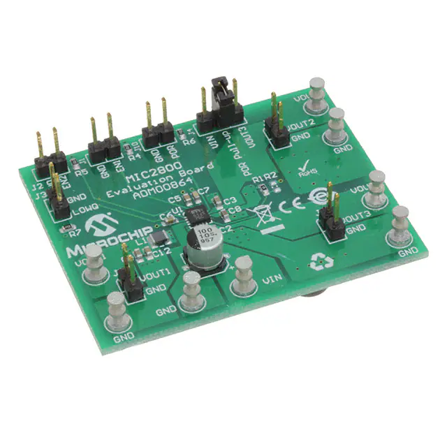
MIC2800 EVALUATION BOARD OVERVIEW
The MIC2800 Evaluation Board has been developed to evaluate the capabilities of the
MIC2800 multi-output (DC-DC and 2 x LDO) device. The board is populated with the
MIC2800-G1JS device and it is set to the following voltages:
• VOUT1 (DC-DC Buck converter): 1.8V
• VOUT2 (LDO1): 1.25V
• VOUT3 (LDO2): 3.3V
The MIC2800-G1JS allows support of the SAMA5D2 family MPUs when operating off
a 5V input rail. However, by populating the board with another MIC2800 IC voltage
option, other power supply solutions can be demonstrated.
The MIC2800 Evaluation Board features independent Enable connectors (EN1 and
EN2). To disable the regulators, a jumper must be placed on J1 (to disable the DC/DC
converter and LDO1) or to J2 (to disable LDO2). Since it is not recommended to leave
EN pins floating, the MIC2800 Evaluation Board features 100 kΩ pull-up resistors, so
the default value when the board is powered is ON.
DS50002656A-page 10
2017 Microchip Technology Inc.
�Product Overview
The MIC2800 Evaluation Board also features a LOWQ pin to switch the functionality of
the DC/DC converter. When the LOWQ is logic high (>1V), the DC/DC converter works
in PWM mode (normal operation mode with 600 mA output current capability). When
the LOWQ is logic low (2.7V is applied. To
disable the device, apply a voltage of 0V to the EN1, EN2 terminals (J1 and/or
J2).
5. Power-on Reset (POR) test point is provided to monitor the POR function (J10).
The power-on reset output will go high after all the output voltages have reached
96% of their nominal voltage and will go low as son as one of the output voltages
go below 91% of its nominal voltage. The POR flag has programmable assertion
delay set by the capacitor placed on CSET pin to ground.
6. The inductance associated with long wires between the power supply and the
board input may cause voltage spikes at load stepping, start-up into heavy loads
or hot wire plug conditions. If the spikes exceed 6V absolute maximum input voltage, the MIC2800 may fail. This behavior is prevented by C9 capacitor (100µF
Al-Electrolytic capacitor) by absorbing voltage spikes.
2017 Microchip Technology Inc.
DS50002656A-page 13
�MIC2800 Evaluation Board User’s Guide
VOUT2
LDO1
VOUT3
LDO2
VOUT1
BUCK
POWER SUPPLY
FIGURE 2-1:
2.3
MIC2800 Evaluation Board – Test Points Description.
EVALUATION BOARD DESCRIPTION
2.3.1
Power-on Reset Pull-up Resistor
The MIC2800 Evaluation Board offers the possibility of connecting the POR pin to
either VIN or VOUT3 (LDO2, 3.3V) by using J4. This provides the flexibility for direct
interfacing with 3.3V systems or directly to VIN when the 3.3V rail is disabled.
2.3.2
Power-on Reset Capacitor (C7)
The MIC2800 has a programmable POR delay set by placing a capacitor on the CSET
pin. This pin is a current source output that charges a capacitor that sets the delay time
for the POR output, from low to high. The current source of 1.25 µA charges a capacitor
up from 0V. When the capacitor reaches 1.25V, the output of the POR is allowed to go
high. The delay time in microseconds is equal to the CSET capacitor in picofarads
(Equation 2-1).
EQUATION 2-1:
PORDelay uS = CSET pF
2.3.3
LOWQ Mode
MIC2800 is 2 MHz 600 mA DC/DC converter with two integrated 300 mA LDOs. This
design combines good overall efficiency with low output noise. However, the DC/DC
converter is always switching in PWM mode. To reduce quiescent current in light-load
conditions, the MIC2800 features a LOWQ pin. In this mode, the DC/DC converter is
disabled and the output voltage is provided by a low noise linear regulator (LDO) capable of supplying 60 mA to the load. In this mode, the other linear regulators (LDO1 and
LDO2) will also be internally limited to 10 mA.
DS50002656A-page 14
2017 Microchip Technology Inc.
�Installation and Operation
2.3.4
Using Fixed and Adjustable Voltage Options
The MIC2800 Evaluation Board is designed for both fixed and adjustable options.
Resistors R1 and R2 are used for setting the output voltage of the adjustable option of
the DC/DC converter: R1 is the top voltage divider resistor and R2 is the bottom voltage
divider resistor. The feedback voltage is 0.8V (nominal) and the output voltage can be
adjusted from 1V to 2V. Note that LDO1 is powered from the DC/DC converter's output,
so in order for LDO1 to maintain good regulation, the DC/DC output voltage should be
minimum VDCDC - VDO.
2.3.5
Output Noise and Ripple Measurements
The MIC2800 Evaluation Board is populated with headers used for measuring output
noise and ripple on both the DC/DC converter and the LDOs (J5, J8 and J9). Each connector is designed to probe the output signal using the local ground as reference. This
is the proper way of measuring low-amplitude ripple signals because it eliminates any
noise caused by long oscilloscope ground leads or ground plane noise.
2.3.6
Board Layout Considerations
It is recommended that the connection between the GND pins of the MIC2800 and
GND terminals of the input capacitors is kept on the TOP of the PCB and no vias
should be placed between them. This will improve transient behavior and decrease
noise. It is also recommended that the TOP GND plane should extend under the
device for optimal noise performance.
2017 Microchip Technology Inc.
DS50002656A-page 15
�MIC2800 Evaluation Board User’s Guide
NOTES:
DS50002656A-page 16
2017 Microchip Technology Inc.
�MIC2800
EVALUATION BOARD
USER’S GUIDE
Appendix A. Schematic and Layouts
A.1
INTRODUCTION
This appendix contains the following schematics and layouts for the MIC2800
Evaluation Board:
•
•
•
•
•
•
•
Board – Schematic
Board – Top Silk
Board – Top Copper and Silk
Board – Top Copper
Board – Bottom Copper
Board – Bottom Copper and Silk
Board – Bottom Silk
2017 Microchip Technology Inc.
DS50002656A-page 17
�BOARD – SCHEMATIC
VOUT1
VIN
U1
100uF
10V
AL-C
GND
C1
10uF
35V
0603
R7
100k
0603
1%
100k
0603
1%
7
100k
0603
1%
EN1
LOWQ
EN2
VIN
SW
15
EN1
1
LOWQ
16
EN2
FB
TP2
C5
C6
0.1uF
16V
0603
GND
GND
4
0.1uF
16V
0603
GND
GND
PGND
MIC2800
L1
5
9
LDO1
LDO2
R1
0R
0603
11
GND
VOUT3
12
POR
13
CSET
3
SGND
C7
0.010uF
25V
0603
GND
GND
R2
C2
C3
10uF
35V
0603
10uF
35V
0603
GND
GND
GND
10uF
35V
0603
GND
2 1
2 1
LOWQ
GND
GND
GND
100k
0603
1%
J10
POR
GND
0.1uF
16V
0603
GND
C8
TP3
TP4 GND
GND
Shunt 2.54mm 1x2
HDR-2.54 Male 1x3
VOUT3
TP6
TP7
TP8
GND
GND
GND
2.2uF
16V
0603
J4 JP1
3
2
1
R6
2 1
2 1
J3
EN1
C12
C4
DNP
J1
EN2
VOUT2
8
VIN
J2
VOUT1
J5
2.2uH
VOUT2
GND
14
CBYP
2
BIAS
10
J8
VOUT3
J9
2 1
C9
R4
R5
LDO
2 1
TP1
VIN
2 1
6
TP5
GND
MIC2800 Evaluation Board User’s Guide
DS50002656A-page 18
A.2
2017 Microchip Technology Inc.
�Schematic and Layouts
A.3
BOARD – TOP SILK
�����
����
�����
5,31�d
�
%��)/
%�d
A


 工商网监
湘ICP备2023018690号
工商网监
湘ICP备2023018690号

