Features
•
•
•
•
•
•
•
•
•
•
Single Supply Voltage Range, 2.7V to 3.6V
Single Supply for Read and Write
Fast Read Access Time – 70 ns
Internal Program Control and Timer
8K Bytes Boot Block with Lockout
Fast Erase Cycle Time – 10 Seconds
Byte-by-Byte Programming – 30 µs/Byte Typical
Hardware Data Protection
DATA Polling for End of Program Detection
Low Power Dissipation
– 25 mA Active Current
– 50 µA CMOS Standby Current
• Typical 10,000 Write Cycles
Description
The AT49BV512 is a 3-volt only, 512K Flash memories organized as 65,536 words of
8 bits each. Manufactured with Atmel’s advanced nonvolatile CMOS technology, the
devices offer access times to 70 ns with power dissipation of just 90 mW over the
commercial temperature range. When the devices are deselected, the CMOS standby
current is less than 50 µA.
512K (64K x 8)
Single 2.7-volt
Battery-Voltage™
Flash Memory
AT49BV512
To allow for simple in-system reprogrammability, the AT49BV512 does not require
high input voltages for programming. Three-volt only commands determine the read
and programming operation of the device. Reading data out of the device is similar to
reading from an EPROM. Reprogramming the AT49BV512 is performed by erasing
Pin Configurations
DIP Top View
Addresses
CE
Chip Enable
OE
Output Enable
WE
Write Enable
I/O0 - I/O7
Data Inputs/Outputs
NC
No Connect
VSOP Top View (8 x 14 mm) or
TSOP Top View (8 x 20 mm)
Type 1
1
2
3
4
5
6
7
8
9
10
11
12
13
14
15
16
32
31
30
29
28
27
26
25
24
23
22
21
20
19
18
17
OE
A10
CE
I/O7
I/O6
I/O5
I/O4
I/O3
GND
I/O2
I/O1
I/O0
A0
A1
A2
A3
32
31
30
29
28
27
26
25
24
23
22
21
20
19
18
17
VCC
WE
NC
A14
A13
A8
A9
A11
OE
A10
CE
I/O7
I/O6
I/O5
I/O4
I/O3
PLCC Top View
A12
A15
NC
NC
VCC
WE
NC
A11
A9
A8
A13
A14
NC
WE
VCC
NC
NC
A15
A12
A7
A6
A5
A4
1
2
3
4
5
6
7
8
9
10
11
12
13
14
15
16
A7
A6
A5
A4
A3
A2
A1
A0
I/O0
4
3
2
1
32
31
30
A0 - A15
NC
NC
A15
A12
A7
A6
A5
A4
A3
A2
A1
A0
I/O0
I/O1
I/O2
GND
5
6
7
8
9
10
11
12
13
29
28
27
26
25
24
23
22
21
14
15
16
17
18
19
20
Function
A14
A13
A8
A9
A11
OE
A10
CE
I/O7
I/O1
I/O2
GND
I/O3
I/O4
I/O5
I/O6
Pin Name
Rev. 1026E–FLASH–06/02
1
�the entire 1 megabit of memory and then programming on a byte-by-byte basis. The typical byte programming time is a fast 30 µs. The end of a program cycle can be optionally
detected by the DATA polling feature. Once the end of a byte program cycle has been
detected, a new access for a read or program can begin. The typical number of program
and erase cycles is in excess of 10,000 cycles.
The optional 8K bytes boot block section includes a reprogramming write lock out feature to provide data integrity. The boot sector is designed to contain user secure code,
and when the feature is enabled, the boot sector is permanently protected from being
reprogrammed.
Block Diagram
DATA INPUTS/OUTPUTS
I/O0 - I/O7
VCC
GND
OE
WE
CE
ADDRESS
INPUTS
OE, CE AND WE
LOGIC
DATA LATCH
INPUT/OUTPUT
BUFFERS
Y DECODER
Y-GATING
X DECODER
MAIN MEMORY
(56K BYTES)
OPTIONAL BOOT
BLOCK (8K BYTES)
Device Operation
FFFFH
2000H
1FFFH
0000H
READ: The AT49BV512 is accessed like an EPROM. When CE and OE are low and
WE is high, the data stored at the memory location determined by the address pins is
asserted on the outputs. The outputs are put in the high impedance state whenever CE
or OE is high. This dual-line control gives designers flexibility in preventing bus
contention.
ERASURE: Before a byte can be reprogrammed, the 64K bytes memory array (or 56K
bytes if the boot block featured is used) must be erased. The erased state of the memory bits is a logical “1”. The entire device can be erased at one time by using a 6-byte
software code. The software chip erase code consists of 6-byte load commands to specific address locations with a specific data pattern (please refer to the Chip Erase Cycle
Waveforms).
After the software chip erase has been initiated, the device will internally time the erase
operation so that no external clocks are required. The maximum time needed to erase
the whole chip is tEC. If the boot block lockout feature has been enabled, the data in the
boot sector will not be erased.
BYTE PROGRAMMING: Once the memory array is erased, the device is programmed
(to a logical “0”) on a byte-by-byte basis. Please note that a data “0” cannot be programmed back to a “1”; only erase operations can convert “0”s to “1”s. Programming is
accomplished via the internal device command register and is a 4 bus cycle operation
(please refer to the Command Definitions table). The device will automatically generate
the required internal program pulses.
The program cycle has addresses latched on the falling edge of WE or CE, whichever
occurs last, and the data latched on the rising edge of WE or CE, whichever occurs first.
Programming is completed after the specified tBP cycle time. The DATA polling feature
may also be used to indicate the end of a program cycle.
2
AT49BV512
1026E–FLASH–06/02
�AT49BV512
BOOT BLOCK PROGRAMMING LOCKOUT: The device has one designated block
that has a programming lockout feature. This feature prevents programming of data in
the designated block once the feature has been enabled. The size of the block is 8K
bytes. This block, referred to as the boot block, can contain secure code that is used to
bring up the system. Enabling the lockout feature will allow the boot code to stay in the
device while data in the rest of the device is updated. This feature does not have to be
activated; the boot block’s usage as a write protected region is optional to the user. The
address range of the boot block is 0000H to 1FFFH.
Once the feature is enabled, the data in the boot block can no longer be erased or programmed. Data in the main memory block can still be changed through the regular
programming method. To activate the lockout feature, a series of six program commands to specific addresses with specific data must be performed. Please refer to the
Command Definitions table.
BOOT BLOCK LOCKOUT DETECTION: A software method is available to determine if
programming of the boot block section is locked out. When the device is in the software
product identification mode (see Software Product Identification Entry and Exit sections)
a read from address location 00002H will show if programming the boot block is locked
out. If the data on I/O0 is low, the boot block can be programmed; if the data on I/O0 is
high, the program lockout feature has been activated and the block cannot be programmed. The software product identification code should be used to return to standard
operation.
PRODUCT IDENTIFICATION: The product identification mode identifies the device and
manufacturer as Atmel. It may be accessed by hardware or software operation. The
hardware operation mode can be used by an external programmer to identify the correct
programming algorithm for the Atmel product.
For details, see Operating Modes (for hardware operation) or Software Product Identification. The manufacturer and device code is the same for both modes.
DATA POLLING: The AT49BV512 features DATA polling to indicate the end of a program cycle. During a program cycle an attempted read of the last byte loaded will result
in the complement of the loaded data on I/O7. Once the program cycle has been completed, true data is valid on all outputs and the next cycle may begin. DATA polling may
begin at any time during the program cycle.
TOGGLE BIT: In addition to DATA polling the AT49BV512 provides another method for
determining the end of a program or erase cycle. During a program or erase operation,
successive attempts to read data from the device will result in I/O6 toggling between
one and zero. Once the program cycle has completed, I/O6 will stop toggling and valid
data will be read. Examining the toggle bit may begin at any time during a program
cycle.
HARDWARE DATA PROTECTION: Hardware features protect against inadvertent programs to the AT49BV512 in the following ways: (a) VCC sense: if V CC is below 1.8V
(typical), the program function is inhibited. (b) Program inhibit: holding any one of OE
low, CE high or WE high inhibits program cycles. (c) Noise filter: Pulses of less than
15 ns (typical) on the WE or CE inputs will not initiate a program cycle.
INPUT LEVELS: While operating with a 2.7V to 3.6V power supply, the address inputs
and control inputs (OE, CE and WE) may be driven from 0 to 5.5V without adversely
affecting the operation of the device. The I/O lines can only be driven from 0 to VCC +
0.6V.
3
1026E–FLASH–06/02
�Command Definition (in Hex)
Command
Sequence
1st Bus
Cycle
Bus
Cycles
Addr
Data
Read
1
Addr
DOUT
Chip Erase
6
5555
Byte
Program
4
Boot Block
Lockout(1)
2nd Bus
Cycle
3rd Bus
Cycle
4th Bus
Cycle
5th Bus
Cycle
6th Bus
Cycle
Addr
Data
Addr
Data
Addr
Data
Addr
Data
Addr
Data
AA
2AAA
55
5555
80
5555
AA
2AAA
55
5555
10
5555
AA
2AAA
55
5555
A0
Addr
DIN
6
5555
AA
2AAA
55
5555
80
5555
AA
2AAA
55
5555
40
Product ID
Entry
3
5555
AA
2AAA
55
5555
90
Product ID
Exit(2)
3
5555
AA
2AAA
55
5555
F0
Product ID
Exit(2)
1
XXXX
F0
Notes:
1. The 8K byte boot sector has the address range 0000H to 1FFFH.
2. Either one of the Product ID exit commands can be used.
Absolute Maximum Ratings*
Temperature Under Bias ............................... -55°C to +125°C
Storage Temperature ..................................... -65°C to +150°C
All Input Voltages
(including NC Pins)
with Respect to Ground ...................................-0.6V to +6.25V
All Output Voltages
with Respect to Ground .............................-0.6V to VCC + 0.6V
*NOTICE:
Stresses beyond those listed under “Absolute
Maximum Ratings” may cause permanent damage to the device. This is a stress rating only and
functional operation of the device at these or any
other conditions beyond those indicated in the
operational sections of this specification is not
implied. Exposure to absolute maximum rating
conditions for extended periods may affect
device reliability.
Voltage on OE
with Respect to Ground ...................................-0.6V to +13.5V
4
AT49BV512
1026E–FLASH–06/02
�AT49BV512
DC and AC Operating Range
Operating
Temperature (Case)
AT49BV512-70
AT49BV512-90
AT49BV512-12
AT49BV512-15
0°C - 70°C
0°C - 70°C
0°C - 70°C
0°C - 70°C
-40°C - 85°C
-40°C - 85°C
-40°C - 85°C
-40°C - 85°C
2.7V to 3.6V
2.7V to 3.6V
2.7V to 3.6V
2.7V to 3.6V
Com.
Ind.
VCC Power Supply
Operating Modes
Mode
Read
Program
(2)
Standby/Write Inhibit
CE
OE
WE
Ai
I/O
VIL
VIL
VIH
Ai
DOUT
VIL
VIH
VIL
Ai
DIN
X
High Z
(1)
VIH
X
X
Program Inhibit
X
X
VIH
Program Inhibit
X
VIL
X
Output Disable
X
VIH
X
VIL
VIL
VIH
High Z
Product Identification
Hardware
A1 - A15 = V IL, A9 = VH,(3), A0 = VIL
Manufacturer Code(4)
A1 - A15 = VIL, A9 = V H,(3), A0 = VIH
Device Code(4)
Software(5)
Notes:
1.
2.
3.
4.
5.
A0 = VIL, A1 - A15 = VIL
Manufacturer Code(4)
A0 = VIH, A1 - A15 = V IL
Device Code(4)
X can be VIL or VIH.
Refer to AC Programming Waveforms.
VH = 12.0V ± 0.5V.
Manufacturer Code: 1FH, Device Code: 03H.
See details under Software Product Identification Entry/Exit.
DC Characteristics
Symbol
Parameter
Condition
ILI
Input Load Current
ILO
Max
Units
VIN = 0V to VCC
10
µA
Output Leakage Current
VI/O = 0V to VCC
10
µA
ISB1
VCC Standby Current CMOS
CE = VCC - 0.3V to VCC
50
µA
ISB2
VCC Standby Current TTL
CE = 2.0V to VCC
1
mA
VCC Active Current
f = 5 MHz; IOUT = 0 mA
25
mA
0.6
V
ICC
(1)
VIL
Input Low Voltage
VIH
Input High Voltage
VOL
Output Low Voltage
IOL = 2.1 mA
VOH
Output High Voltage
IOH = -100 µA; VCC = 3.0V
Note:
Min
2.0
V
0.45
2.4
V
V
1. In the erase mode, ICC is 50 mA.
5
1026E–FLASH–06/02
�AC Read Characteristics
AT49BV512-70
Symbol
Parameter
tACC
Min
Max
AT49BV512-90
Min
Max
AT49BV512-12
Min
Max
AT49BV512-15
Min
Max
Units
Address to Output Delay
70
90
120
150
ns
tCE
(1)
CE to Output Delay
70
90
120
150
ns
tOE
(2)
OE to Output Delay
0
35
40
50
0
70
ns
tDF
(3, 4)
CE or OE to Output Float
0
25
30
0
40
ns
Output Hold from OE, CE or
Address, whichever occurred first
0
tOH
0
25
0
0
0
0
ns
AC Read Waveforms(1)(2)(3)(4)
ADDRESS
ADDRESS VALID
CE
tCE
OE
tACC
OUTPUT
Notes:
6
HIGH Z
tDF
tOH
OUTPUT VALID
1. CE may be delayed up to tACC - tCE after the address transition without impact on tACC.
2. OE may be delayed up to tCE - tOE after the falling edge of CE without impact on tCE or by tACC - tOE after an address change
without impact on tACC.
3. tDF is specified from OE or CE whichever occurs first (CL - 5 pF).
4. This parameter is characterized and is not 100% tested.
AT49BV512
1026E–FLASH–06/02
�AT49BV512
Input Test Waveforms and
Measurement Level
AC
DRIVING
LEVELS
2.4V
AC
MEASUREMENT
LEVEL
1.5V
0.4V
tR, tF < 5 ns
Output Test Load
3.0V
1.8K
OUTPUT
PIN
1.3K
100 pF
Pin Capacitance
f = 1 MHz, T = 25°C(1)
Symbol
Typ
Max
Units
Conditions
CIN
4
6
pF
VIN = 0V
COUT
8
12
pF
VOUT = 0V
Note:
1. This parameter is characterized and is not 100% tested.
7
1026E–FLASH–06/02
�AC Byte Load Characteristics
Symbol
Parameter
Min
tAS, tOES
Address, OE Set-up Time
tAH
Address Hold Time
tCS
Max
Units
0
ns
100
ns
Chip Select Set-up Time
0
ns
tCH
Chip Select Hold Time
0
ns
tWP
Write Pulse Width (WE or CE)
200
ns
tDS
Data Set-up Time
100
ns
tDH, tOEH
Data, OE Hold Time
0
ns
tWPH
Write Pulse Width High
200
ns
AC Byte Load Waveforms
WE Controlled
OE
tOES
tOEH
ADDRESS
tAS
tAH
tCH
CE
tCS
WE
tWP
tDS
tWPH
tDH
DATA IN
CE Controlled
OE
tOES
tOEH
ADDRESS
tAS
tAH
tCH
WE
tCS
CE
tWP
tDS
tWPH
tDH
DATA IN
8
AT49BV512
1026E–FLASH–06/02
�AT49BV512
Program Cycle Characteristics
Symbol
Parameter
Min
tBP
Byte Programming Time
tAS
Address Set-up Time
tAH
Typ
Max
Units
µs
30
0
ns
Address Hold Time
100
ns
tDS
Data Set-up Time
100
ns
tDH
Data Hold Time
0
ns
tWP
Write Pulse Width
200
ns
tWPH
Write Pulse Width High
200
ns
tEC
Erase Cycle Time
10
seconds
Program Cycle Waveforms
PROGRAM CYCLE
OE
CE
tWP
tWPH
tBP
WE
tAH
tAS
A0-A15
5555
tDH
2AAA
5555
ADDRESS
tDS
AA
DATA
55
INPUT
DATA
A0
Chip Erase Cycle Waveforms
OE
CE
tWP
tWPH
WE
tAS
A0-A15
tDH
tAH
5555
2AAA
5555
5555
2AAA
5555
tDS
DATA
Note:
tEC
AA
55
80
AA
55
10
BYTE 0
BYTE 1
BYTE 2
BYTE 3
BYTE 4
BYTE 5
OE must be high only when WE and CE are both low.
9
1026E–FLASH–06/02
�Data Polling Characteristics(1)
Symbol
Parameter
Min
tDH
Data Hold Time
tOEH
OE Hold Time
Max
OE to Output Delay
tWR
Write Recovery Time
Units
0
ns
10
ns
(2)
tOE
Notes:
Typ
ns
0
ns
1. These parameters are characterized and not 100% tested.
2. See tOE spec in AC Read Characteristics.
Data Polling Waveforms
WE
CE
tOEH
OE
tDH
tOE
tWR
I/O7
A0-A15
An
An
An
An
An
Toggle Bit Characteristics(1)
Symbol
Parameter
tDH
Data Hold Time
tOEH
OE Hold Time
Min
OE to Output Delay
tOEHP
OE High Pulse
tWR
Write Recovery Time
Max
Units
0
ns
10
ns
(2)
tOE
Notes:
Typ
ns
150
ns
0
ns
1. These parameters are characterized and not 100% tested.
2. See tOE spec in AC Read Characteristics.
Toggle Bit Waveforms(1)(2)(3)
WE
CE
tOEH
tOEHP
OE
tDH
I/O6
Notes:
10
tOE
tWR
HIGH Z
1. Toggling either OE or CE or both OE and CE will operate toggle bit. The tOEHP specification must be met by the toggling
input(s).
2. Beginning and ending state of I/O6 will vary.
3. Any address location may be used but the address should not vary.
AT49BV512
1026E–FLASH–06/02
�AT49BV512
Boot Block Lockout Feature
Enable Algorithm(1)
Software Product
Identification Entry(1)
LOAD DATA AA
TO
ADDRESS 5555
LOAD DATA AA
TO
ADDRESS 5555
LOAD DATA 55
TO
ADDRESS 2AAA
LOAD DATA 55
TO
ADDRESS 2AAA
LOAD DATA 90
TO
ADDRESS 5555
LOAD DATA 80
TO
ADDRESS 5555
ENTER PRODUCT
IDENTIFICATION
MODE(2)(3)(5)
LOAD DATA AA
TO
ADDRESS 5555
Software Product
Identification Exit(1)
LOAD DATA AA
TO
ADDRESS 5555
LOAD DATA 55
TO
ADDRESS 2AAA
OR
LOAD DATA 55
TO
ADDRESS 2AAA
LOAD DATA F0
TO
ANY ADDRESS
LOAD DATA 40
TO
ADDRESS 5555
EXIT PRODUCT
IDENTIFICATION
MODE(4)
LOAD DATA F0
TO
ADDRESS 5555
PAUSE 1 second(2)
Notes:
1. Data Format: I/O7 - I/O0 (Hex);
Address Format: A14 - A0 (Hex).
2. Boot block lockout feature enabled.
EXIT PRODUCT
IDENTIFICATION
MODE(4)
Notes:
1. Data Format: I/O7 - I/O0 (Hex);
Address Format: A14 - A0 (Hex).
2. A1 - A15 = VIL.
Manufacture Code is read for A0 = VIL;
Device Code is read for A0 = VIH.
3. The device does note remain in identification mode if
powered down.
4. The device returns to standard operation mode.
5. Manufacturers Code: 1FH
Device Code: 03H.
11
1026E–FLASH–06/02
�Ordering Information(1)
ICC (mA)
tACC
(ns)
Active
Standby
70
25
90
120
150
Note:
Ordering Code
Package
Operation Range
0.05
AT49BV512-70JC
AT49BV512-70PC
AT49BV512-70TC
AT49BV512-70VC
32J
32P6
32T
32V
Commercial
(0°C - 70°C)
25
0.05
AT49BV512-70JI
AT49BV512-70PI
AT49BV512-70TI
AT49BV512-70VI
32J
32P6
32T
32V
Industrial
(-40°C - 85°C)
25
0.05
AT49BV512-90JC
AT49BV512-90PC
AT49BV512-90TC
AT49BV512-90VC
32J
32P6
32T
32V
Commercial
(0°C - 70°C)
25
0.05
AT49BV512-90JI
AT49BV512-90PI
AT49BV512-90TI
AT49BV512-90VI
32J
32P6
32T
32V
Industrial
(-40°C - 85°C)
25
0.05
AT49BV512-12JC
AT49BV512-12PC
AT49BV512-12TC
AT49BV512-12VC
32J
32P6
32T
32V
Commercial
(0°C - 70°C)
25
0.05
AT49BV512-12JI
AT49BV512-12PI
AT49BV512-12TI
AT49BV512-12VI
32J
32P6
32T
32V
Industrial
(-40°C - 85°C)
25
0.05
AT49BV512-15JC
AT49BV512-15PC
AT49BV512-15TC
AT49BV512-15VC
32J
32P6
32T
32V
Commercial
(0°C - 70°C)
25
0.05
AT49BV512-15JI
AT49BV512-15PI
AT49BV512-15TI
AT49BV512-15VI
32J
32P6
32T
32V
Industrial
(-40°C - 85°C)
1. The AT49BV512 has as optional boot block feature. The part number shown in the Ordering Information table is for devices
with the boot block in the lower address range (i.e., 0000H to 1FFFH). Users requiring boot block protection to be in the
higher address range should contact Atmel.
Package Type
32J
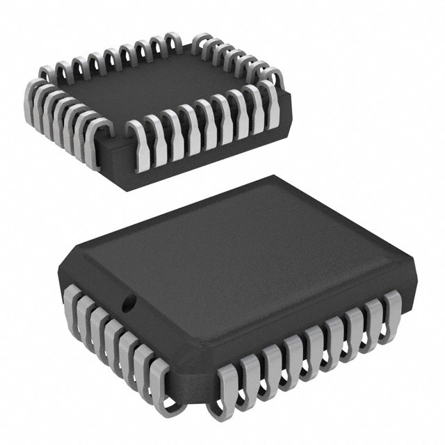
32-lead, Plastic J-leaded Chip Carrier Package (PLCC)
32P6
32-lead, 0.600" Wide, Plastic Dual Inline Package (PDIP)
32T
32-lead, Thin Small Outline Package (TSOP) (8 x 20 mm)
32V
32-lead, Thin Small Outline Package (VSOP) (8 x 14 mm)
12
AT49BV512
1026E–FLASH–06/02
�AT49BV512
Packaging Information
32J – PLCC
1.14(0.045) X 45˚
PIN NO. 1
IDENTIFIER
1.14(0.045) X 45˚
0.318(0.0125)
0.191(0.0075)
E1
E2
B1
E
B
e
A2
D1
A1
D
A
0.51(0.020)MAX
45˚ MAX (3X)
COMMON DIMENSIONS
(Unit of Measure = mm)
D2
Notes:
1. This package conforms to JEDEC reference MS-016, Variation AE.
2. Dimensions D1 and E1 do not include mold protrusion.
Allowable protrusion is .010"(0.254 mm) per side. Dimension D1
and E1 include mold mismatch and are measured at the extreme
material condition at the upper or lower parting line.
3. Lead coplanarity is 0.004" (0.102 mm) maximum.
SYMBOL
MIN
NOM
MAX
A
3.175
–
3.556
A1
1.524
–
2.413
A2
0.381
–
–
D
12.319
–
12.573
D1
11.354
–
11.506
D2
9.906
–
10.922
E
14.859
–
15.113
E1
13.894
–
14.046
E2
12.471
–
13.487
B
0.660
–
0.813
B1
0.330
–
0.533
e
NOTE
Note 2
Note 2
1.270 TYP
10/04/01
R
2325 Orchard Parkway
San Jose, CA 95131
TITLE
32J, 32-lead, Plastic J-leaded Chip Carrier (PLCC)
DRAWING NO.
REV.
32J
B
13
1026E–FLASH–06/02
�32P6 – PDIP
D
PIN
1
E1
A
SEATING PLANE
A1
L
B
B1
e
E
0º ~ 15º
C
COMMON DIMENSIONS
(Unit of Measure = mm)
REF
MIN
NOM
MAX
A
–
–
4.826
A1
0.381
–
–
D
41.783
–
42.291
E
15.240
–
15.875
E1
13.462
–
13.970
B
0.356
–
0.559
B1
1.041
–
1.651
L
3.048
–
3.556
C
0.203
–
0.381
eB
15.494
–
17.526
SYMBOL
eB
Note:
1. Dimensions D and E1 do not include mold Flash or Protrusion.
Mold Flash or Protrusion shall not exceed 0.25 mm (0.010").
e
NOTE
Note 1
Note 1
2.540 TYP
09/28/01
R
14
2325 Orchard Parkway
San Jose, CA 95131
TITLE
32P6, 32-lead (0.600"/15.24 mm Wide) Plastic Dual
Inline Package (PDIP)
DRAWING NO.
32P6
REV.
B
AT49BV512
1026E–FLASH–06/02
�AT49BV512
32T – TSOP
PIN 1
0º ~ 8º
c
Pin 1 Identifier
D1 D
L
b
e
L1
A2
E
A
GAGE PLANE
SEATING PLANE
COMMON DIMENSIONS
(Unit of Measure = mm)
A1
MIN
NOM
MAX
A
–
–
1.20
A1
0.05
–
0.15
A2
0.95
1.00
1.05
D
19.80
20.00
20.20
D1
18.30
18.40
18.50
Note 2
E
7.90
8.00
8.10
Note 2
L
0.50
0.60
0.70
SYMBOL
Notes:
1. This package conforms to JEDEC reference MO-142, Variation BD.
2. Dimensions D1 and E do not include mold protrusion. Allowable
protrusion on E is 0.15 mm per side and on D1 is 0.25 mm per side.
3. Lead coplanarity is 0.10 mm maximum.
L1
0.25 BASIC
b
0.17
0.22
0.27
c
0.10
–
0.21
e
NOTE
0.50 BASIC
10/18/01
R
2325 Orchard Parkway
San Jose, CA 95131
TITLE
32T, 32-lead (8 x 20 mm Package) Plastic Thin Small Outline
Package, Type I (TSOP)
DRAWING NO.
REV.
32T
B
15
1026E–FLASH–06/02
�32V – VSOP
PIN 1
0º ~ 8º
c
Pin 1 Identifier
D1 D
L
b
e
L1
A2
E
A
GAGE PLANE
SEATING PLANE
COMMON DIMENSIONS
(Unit of Measure = mm)
A1
MIN
NOM
MAX
A
–
–
1.20
A1
0.05
–
0.15
A2
0.95
1.00
1.05
D
13.80
14.00
14.20
D1
12.30
12.40
12.50
Note 2
E
7.90
8.00
8.10
Note 2
L
0.50
0.60
0.70
SYMBOL
Notes:
1. This package conforms to JEDEC reference MO-142, Variation BA.
2. Dimensions D1 and E do not include mold protrusion. Allowable
protrusion on E is 0.15 mm per side and on D1 is 0.25 mm per side.
3. Lead coplanarity is 0.10 mm maximum.
L1
0.25 BASIC
b
0.17
0.22
0.27
c
0.10
–
0.21
e
NOTE
0.50 BASIC
10/18/01
R
16
2325 Orchard Parkway
San Jose, CA 95131
TITLE
32V, 32-lead (8 x 14 mm Package) Plastic Thin Small Outline
Package, Type I (VSOP)
DRAWING NO.
REV.
32V
B
AT49BV512
1026E–FLASH–06/02
�Atmel Headquarters
Atmel Operations
Corporate Headquarters
Memory
2325 Orchard Parkway
San Jose, CA 95131
TEL 1(408) 441-0311
FAX 1(408) 487-2600
Europe
Atmel Sarl
Route des Arsenaux 41
Case Postale 80
CH-1705 Fribourg
Switzerland
TEL (41) 26-426-5555
FAX (41) 26-426-5500
Asia
Room 1219
Chinachem Golden Plaza
77 Mody Road Tsimshatsui
East Kowloon
Hong Kong
TEL (852) 2721-9778
FAX (852) 2722-1369
Japan
9F, Tonetsu Shinkawa Bldg.
1-24-8 Shinkawa
Chuo-ku, Tokyo 104-0033
Japan
TEL (81) 3-3523-3551
FAX (81) 3-3523-7581
2325 Orchard Parkway
San Jose, CA 95131
TEL 1(408) 441-0311
FAX 1(408) 436-4314
RF/Automotive
Theresienstrasse 2
Postfach 3535
74025 Heilbronn, Germany
TEL (49) 71-31-67-0
FAX (49) 71-31-67-2340
Microcontrollers
2325 Orchard Parkway
San Jose, CA 95131
TEL 1(408) 441-0311
FAX 1(408) 436-4314
La Chantrerie
BP 70602
44306 Nantes Cedex 3, France
TEL (33) 2-40-18-18-18
FAX (33) 2-40-18-19-60
ASIC/ASSP/Smart Cards
1150 East Cheyenne Mtn. Blvd.
Colorado Springs, CO 80906
TEL 1(719) 576-3300
FAX 1(719) 540-1759
Biometrics/Imaging/Hi-Rel MPU/
High Speed Converters/RF Datacom
Avenue de Rochepleine
BP 123
38521 Saint-Egreve Cedex, France
TEL (33) 4-76-58-30-00
FAX (33) 4-76-58-34-80
Zone Industrielle
13106 Rousset Cedex, France
TEL (33) 4-42-53-60-00
FAX (33) 4-42-53-60-01
1150 East Cheyenne Mtn. Blvd.
Colorado Springs, CO 80906
TEL 1(719) 576-3300
FAX 1(719) 540-1759
Scottish Enterprise Technology Park
Maxwell Building
East Kilbride G75 0QR, Scotland
TEL (44) 1355-803-000
FAX (44) 1355-242-743
e-mail
literature@atmel.com
Web Site
http://www.atmel.com
© Atmel Corporation 2002.
Atmel Corporation makes no warranty for the use of its products, other than those expressly contained in the Company’s standard warranty
which is detailed in Atmel’s Terms and Conditions located on the Company’s web site. The Company assumes no responsibility for any errors
which may appear in this document, reserves the right to change devices or specifications detailed herein at any time without notice, and does
not make any commitment to update the information contained herein. No licenses to patents or other intellectual property of Atmel are granted
by the Company in connection with the sale of Atmel products, expressly or by implication. Atmel’s products are not authorized for use as critical
components in life support devices or systems.
ATMEL ® is the registered trademark of Atmel. Battery-Voltage ™ is the trademark of Atmel.
Other terms and product names may be the trademarks of others.
Printed on recycled paper.
1026E–FLASH–06/02
xM
�