APPLICATION NOTE
User Guide for Atmel ATA6870 and Atmel ATmega32HVB
Evaluation Kit Hardware
ATA6870-DK10
Features
● Evaluation of Atmel® ATA6870
● Monitoring of 12 battery cells
● Monitoring:
● Overvoltage (every cell)
● Undervoltage (every cell)
● Overheating
● Overcurrent
● Open clamp detection
● 12-bit battery cell measurement
● 12-bit temperature measurement
● Controlling of charge/discharge FETs
● Status LEDs for easy evaluation
● Charge balancing
● Coulomb counting for SOC determination
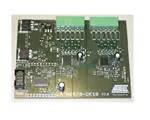
Figure 1.
Atmel ATA6870-DK10
9228C-AUTO-02/15
�1.
Introduction
The Atmel® ATA6870-DK10 is a demonstration board for the Atmel ATA6870, which offers an easy way to start evaluation of
battery applications using the Atmel ATmega32HVB in combination with the Atmel ATA6870. The included software
demonstrates implementation of a 12 Cell Battery Management System. The supplied code serves as an example of how to
use the Atmel ATMega32HVB and Atmel ATA6870 together. The example is not a complete application intended for use
with smart batteries, and it is best to use the devices in a slightly different way in a smart battery application.
2.
Safety Precautions When Using Li-ion Batteries
Please observe the safety guidelines supplied with the batteries. If improperly used or defective, li-ion and polymer batteries
and packs may explode and cause a fire.
3.
Demonstration Board
The Atmel ATA6870-DK10 was developed to allow easy evaluation of control software for a microcontroller which controls
multiple Atmel ATA6870s. The sample code supplied demonstrates a simple permanent running measurement of voltages
and temperatures.
Figure 3-1. Board Concept
Cell 12
Cell 11
ATA6870
ATA6870
Cell 02
Cell 01
Charge/
Discharge
Control Unit
Monitoring (V,T)
Coulomb counting
ATmega32HVB
2
ATA6870-DK10 [APPLICATION NOTE]
9228C–AUTO–02/15
�3.1
System Start
Follow these steps to launch the system.
3.1.1
Installing the Hardware
●
Connect the load/charger to be powered between pack+ and pack- on J1
●
●
Connect the battery cell stack to the screw connectors on the demonstration board
●
●
3.1.2
For demonstration purposes it is possible to use a resistor to simulate a load
Led 1 indicates the enabled status of the demonstration board (controlled by microcontroller SW)
In case of emulating cells such as a voltage divider, apply sufficient voltage (see Section 3.3 “Powering the Board” on
page 5)
Number of Cells
It is possible to run the board with a reduced number of cells. The minimum voltage for each IC is 6.9V. Cell 1 and cell 6
(MBAT) have to be connected. The missing cells should be connected to the upper cell potential of the module. For further
information refer to the Atmel ATA6870 datasheet Section 7.3: Reduced Number of Battery Cells Configuration. For the
voltage range see Section 3.3 “Powering the Board” on page 5. If fewer than 6 cells are used per IC, the config.h file should
be adjusted (CELLSIC# under General Setting). See Section 4.1 “Supplied Code” on page 7 for further information on how to
configure the supplied software correctly.
3.2
The Demonstration Board
Figure 3-2. Evaluation Board with 2 Stacked Atmel ATA6870 and Atmel ATMega32HVB
ATA6870-DK10 [APPLICATION NOTE]
9228C–AUTO–02/15
3
�3.2.1
On-board Features
The demonstration board includes the following items:
● 2 Atmel® ATA6870 QFN 7mm 7mm
●
●
●
Atmel ATMega32HVB
12 external N-channel MOSFETs for balancing of battery cells
Connectors
●
ISP connector for programming/debugging the Atmel ATMega32HVB
●
Screw connectors for connecting up to 12 battery cells
Table 3-1.
Connector Overview
J7
Function
J8
Function
1
CELL-
1
VDDHVM
2
PACK-
2
3
4
VFET
5
3
VCC
4
GND
5
IRQ
6
GND
6
CLK
7
OD
7
MISO
8
OC
8
MOSI
9
RESET
9
SCK
10
GND
10
CS_N
J1
Connector for charger/device to be powered
J2
ISP connector
J3
Upper battery stack (cells 7-12)
J4
Bottom battery stack (cells 1-6)
J9
Jumper to enable/disable MISO line of Atmel ATA6870
J9 should never be set while the Atmel ATmega32HVB is being programmed or while it is entering debug mode. It can be
mounted as soon as AVR Studio prompts for additional SPI lines to be connected in debug mode or after the device has
been correctly programmed.
4
ATA6870-DK10 [APPLICATION NOTE]
9228C–AUTO–02/15
�Figure 3-3. Connectors
3.3
Powering the Board
3.3.1
Power Supply
The board supports supply voltages from 13.8V (6.9V per Atmel ATA6870) to 60V. However, to run the board on voltages
below 24V the ZDiode D3 needs to be replaced with a jumper to supply the Atmel® ATmega32HVB with sufficient voltage. If
the jumper is mounted, the stack voltage should not exceed 48V! The Atmel ATmega32HVB supports operating voltage from
4V to 24V.
3.3.2
Emulating Cells
Battery cells can be emulated by connecting a voltage divider to the specified clamps. Section 3.1.1 “Installing the Hardware”
on page 3 describes how to connect cells. The voltage limits for this setup are the same as for real batteries. Section 3.3.1
“Power Supply” on page 5 specifies these limits.
ATA6870-DK10 [APPLICATION NOTE]
9228C–AUTO–02/15
5
�4.
Software Description: Monitoring of Up to 12 Battery Cells
The supplied code is documented and easy to adjust for verifying the functions of the Atmel® ATA6870 and start BMS
application development work.
After the board has been connected as described above the microcontroller automatically starts a cyclic measurement of
voltages, temperature, and current. LED 1 indicates these cyclic measurements. It toggles in default operation. A
continuously illuminated LED1 indicates an open clamp. See Section 4.2 “Open Cell Check” on page 7 for more information
about open clamp detection. LED 2 indicates that for some reason the MOSFETS have been disabled. The default software
disables the FETs in case of these events:
● Overvoltage (at least 1 cell exceeds the upper default threshold of 4.2V)
●
●
●
●
Undervoltage (at least 1 cell exceeds the lower default threshold of 2.5V)
Overcurrent (the current through the shunt exceeds the default threshold of 80mA)
Overheating (the temperature exceeds the upper threshold, default value is 60°C)
Low temperature threshold (the default threshold is -20°C)
LED 3 indicates whether the Atmel ATA6870s are turned on or not. An active LED indicates that the Atmel ATA6870s are
enabled.
Table 4-1.
LED Functions
LED
Function
LED 1
Indicates clamp is open when permanently illuminated
Indicates cyclic measurements when blinking
LED 2
On indicates disabled MOSFETs for one of the reasons listed above
LED 3
On indicates active Atmel ATA6870
The Atmel ATmega32HVB has no clock divider to provide an external slower clock than 1/2 CPU clock. Requirement of
Atmel ATA6870 is fCLK > 2 fSPI. Hence, the clock frequency of 1MHz is mandatory to provide a 500kHz clock for the ADCs
of the Atmel ATA6870 and 250kHz for SPI.
6
ATA6870-DK10 [APPLICATION NOTE]
9228C–AUTO–02/15
�4.1
Supplied Code
4.1.1
config.h
This section refers to the config.h file provided in the zip archive with this Application Note. Only values in the User Setting
paragraph should be changed!
------------- GENERAL SETTING-------------------------------CELLSIC#
Selecting which Cells are used Bits 0-5 -> Cells 1-6
------------- TEMPERATURE SETTING---------------------------RES_REF#
Value of the mounted reference resistor (default: 3300)
T_TLS
Temperature belonging to the first Value in the lookup
table (index 0, default: -20)
T_TLE
Temperature belonging to the last value in the lookup
table (default: 80)
T_TLSZ
Temperature step size used in the lookup table (default:
1)
T_LOWERTHRESHOLD
Lower temperature threshold
T_UPPERTHRESHOLD
Upper temperature threshold
------------- COULOMBCOUNTER SETTING------------------------SHUNT_RESISTANCE
Value of the shunt resistor in mOhm
RCC_CONVERSIONPERIOD
The cycle times for the Regular Current Check
0x00 - 256ms (default)
0x01 - 512ms
0x02 - 1s
0x11 - 2s
RCC_DIVIDEDSZ
0x01 to enable divided Voltage (Current) stepsize
RCC_CHARGETHRESHOLD
Threshold for charging current, exceeding the
threshold will turn off the Mosfets
RCC_DISCHARGETHRESHOLD
Threshold for discharging current, exceeding the
threshold will turn off the Mosfets
Other values should not be changed in the default HW setup!
4.2
Open Cell Check
The implemented function checks for open clamps by measuring the cell voltages two times. During the first check a normal
measurement is completed and the values stored. During the second check the voltages are measured while the discharge
function for all cells is active. If the two measurements for the same cell differ by more than 100mV it is very likely that one or
more cells are not properly connected. The implemented method cannot be used to determine which cell is not properly
connected. A continuously illuminated LED1 indicates an open clamp.
4.3
Voltage Measurements
The standard software loop measures the voltage ADC value and the offset ADC value for every cell and checks for
overvoltage and undervoltage once per cycle. Further information about the acquiring of voltages can be found in the Atmel®
ATA6870 datasheet Section 7.5.1. The formula for calculating the voltage:
V acq – V offset
Voltage (Cell) = 4V ---------------------------------
3031 – V offset
ATA6870-DK10 [APPLICATION NOTE]
9228C–AUTO–02/15
7
�4.4
Temperature Measurements
The default software only measures channel 1 of chip 1. The temperature sensors are based on a resistor divider using a
standard resistor and an NTC resistor. This resistor divider is connected to the reference of the ADC for temperature
measuring. Because the ADC is sharing the same reference value, the output of temperature measurement with ADC is ratio
metric. Further information is found in the Atmel ATA6870 datasheet Section 7.5.3: Temperature Channel.
For this application Atmel recommends using Res_Ref1 = 3.3k and RES_NTC1 R25 = 10k, B = 3435. The software
supplied for this board uses these values as default. The function uses a lookup table to determine the temperature. This
table has to be edited if an NTC other than the recommended one is used. The values in the lookup table range from –20°C
(index 0) to +80°C (index 100). These values can be edited via the config.h file in the User Settings section. More
Information about this file can be found in Section 4.1 “Supplied Code” on page 7. The calculation of RES_NTC is carried out
based on the formula provided in the Atmel ATA6870 datasheet Section 7.5.3:
RES_NTC(1)
8
8
adc (out) = 2048 1 + --------------------------------------------------------------------------- ------ – ------
(RES_NTC(1) + RES_REF(1)) 15 10
When using another NTC, the LookupADC.txt has to be edited to match the NTC used.
4.5
State of Charge Measurements
Highly precise SOC measurement is possible by combining the features of the Atmel ATmega32HVB and the Atmel
ATA6870. The coulomb counting feature of the Atmel ATmega32HVB enables highly precise measurements of the change
in the state of charge. Frequent reading of the current in a shunt is used to update the SOC frequently. The acquired cell
voltages and temperatures can be used to determine the SOC without the Atmel ATmega32HVB. The easiest way is to
compare the SOC measured by the added/extracted charge with the calculated SOC using the cell voltage, temperature,
and the data provided by the manufacturer of the cells. Further information regarding the coulomb counting ADC as well as
an implementation suitable for the Atmel ATmega16HVA is found in Application Note AVR352.
4.6
Overcurrent Protection
The current through the shunt is calculated by measured voltage drop. The limit can be set via the CADRDC/CADRCC
register. The step size depends on the settings of the CADCSRC register and the shunt used. For further information about
limiting current see the Atmel ATmega32HVB datasheet Section 19.4: Regular Current Detection Operation. The supplied
software allows the feature to be tested by adjusting the values in the config.h file. More Information about this file can be
found in Section 4.1 “Supplied Code” on page 7. Values/part of the code should only be changed if you are aware of possible
consequences. The default implementation continuously measures the current and generates an interrupt if the entered
thresholds are exceeded. The thresholds are defined in the config.h file. The thresholds are written to the registers in the
function CCinit in the Atmel ATA6870_func.c file. Refer to the features of the Atmel ATmega32HVB in the coulomb counter
section to learn more about the time the controller waits for the values to be written.
C Code Example
CADRCC = RCC_CADRCC;
while(CADCSRA & (1
很抱歉,暂时无法提供与“ATA6870-DK10”相匹配的价格&库存,您可以联系我们找货
免费人工找货