APPLICATION NOTE
Atmel AVR600: STK600 Expansion, Routing and Socket
Boards
Atmel Microcontrollers
Introduction
This application note describes the process of developing new routing, socket and
expansion cards for the Atmel STK®600. It also describes the physical parameters for
creating such cards.
The STK600 starter kit from Atmel has a sandwich design to match a specific part
package and pin out to the generic pin headers. It also features an expansion area
where most part pins are available.
While the variety of IC packages is relatively limited, the number of possible pinouts
increases rapidly with the number of pins. I.e. a 6-pin IC can have 720 (6!) different
pinouts!
The routing / socket card design provides a lowcost solution to support upcoming
devices as the socket is the cost driving factor.
STK600 users might also want to create their own routing cards to include
specialized hardware to prototype their own design.
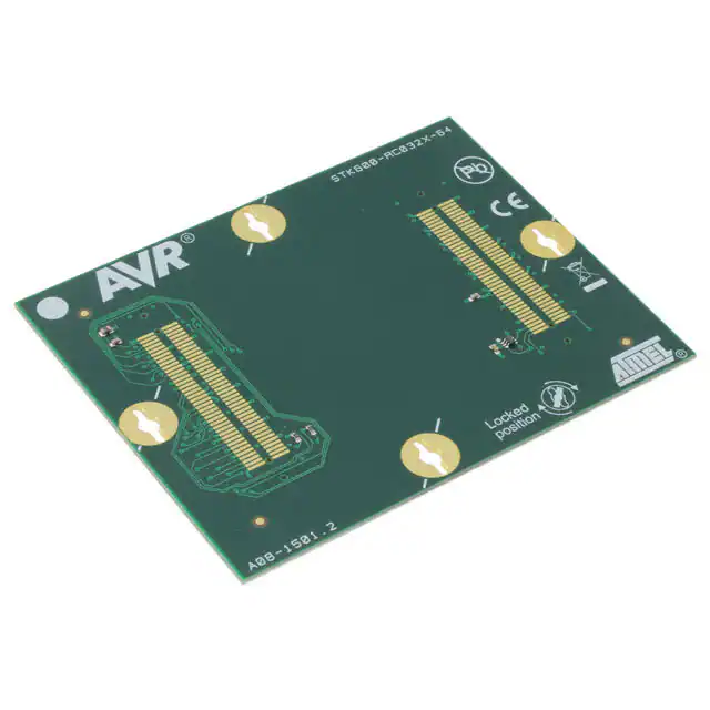
Figure 1.
STK600 router and socket card.
8170C−AVR−03/2013
�Table of Contents
1. Routing Cards ...................................................................................... 3
1.1 Connector footprints .......................................................................................... 3
1.2 Physical dimensions and component placement .............................................. 4
1.3 Atmel STK600 socket connectors pinout .......................................................... 5
1.3.1 Signal descriptions .............................................................................. 8
2. Socket Cards ..................................................................................... 10
2.1 Power design issues ....................................................................................... 10
2.2 Connector MPN............................................................................................... 10
2.3 Physical dimensions and component placement ............................................ 10
3. Expansion Cards ................................................................................ 11
3.1 Connector MPN............................................................................................... 11
3.2 Physical dimensions and component placement ............................................ 12
3.3 Atmel STK600 expansion connectors pinout .................................................. 13
4. ID System .......................................................................................... 17
4.1 Signal usage ................................................................................................... 17
4.2 ID functions ..................................................................................................... 18
4.3 Examples ........................................................................................................ 19
5. Design Example ................................................................................. 20
6. Revision History ................................................................................. 22
Atmel AVR600: STK600 Expansion, Routing and Socket Boards [APPLICATION NOTE]
8170C−AVR−03/2013
2
�1.
Routing Cards
The routing cards sit between the generic socket card and the Atmel STK600. It has one pair of electric pads
underneath to mate with the STK600 spring loaded connector, and one pair of pads on top where the socket card
connector connects. A part specific card with the target IC soldered on can be viewed as a routing card without the top
pads.
1.1
Connector footprints
A routing card should have pads to mate with the following spring loaded connectors:
Table 1-1.
Router card connectors.
Manufacturer and MPN
Quantity
Comment
SAMTEC, FSI-140-03-G-D-AD
2
80-pins to socket card (top)
SAMTEC, FSI-150-03-G-D-AD
2
100-pins to STK600 (bottom)
Figure 1-1. PCB land pattern for mating to FSI connectors.
Atmel AVR600: STK600 Expansion, Routing and Socket Boards [APPLICATION NOTE]
8170C−AVR−03/2013
3
�1.2
Physical dimensions and component placement
Figure 1-2. Routing card connector pad placement and dimensions.
Figure 1-3. Clip hole dimensions.
The board thickness should be 1.6mm to be compatible with the clips.
Note:
Components on the main board might conflict with through hole mounted or secondary side mounted components.
Areas with such components are highlighted in Figure 1-4.
Atmel AVR600: STK600 Expansion, Routing and Socket Boards [APPLICATION NOTE]
8170C−AVR−03/2013
4
�Figure 1-4. Height restricted areas due to main board components.
1.3
Atmel STK600 socket connectors pinout
Figure 1-5 shows the pinout for the STK600 headers. This corresponds to the routing card connectors J1 and J2.
Figure 1-5. STK600 socket connectors’ pinout.
Atmel AVR600: STK600 Expansion, Routing and Socket Boards [APPLICATION NOTE]
8170C−AVR−03/2013
5
�Table 1-2.
Atmel STK600 J201 left, routing card connector J1 pinout.
Signal name
Pin number
Signal name
VTG
2
1
GND
PA1
4
3
PA0
PA3
6
5
PA2
PA5
8
7
PA4
PA7
10
9
PA6
VTG
12
11
GND
PB1
14
13
PB0
PB3
16
15
PB2
PB5
18
17
PB4
PB7
20
19
PB6
VTG
22
21
GND
PC1
24
23
PC0
PC3
26
25
PC2
PC5
28
27
PC4
PC7
30
29
PC6
VTG
32
31
GND
PD1
34
33
PD0
PD3
36
35
PD2
PD5
38
37
PD4
PD7
40
39
PD6
VTG
42
41
GND
PE1
44
43
PE0
PE3
46
45
PE2
PE5
48
47
PE4
PE7
50
49
PE6
VTG
52
51
GND
PF1
54
53
PF0
PF3
56
55
PF2
PF5
58
57
PF4
PF7
60
59
PF6
VTG
62
61
GND
PG1
64
63
PG0
PG3
66
65
PG2
PG5
68
67
PG4
PG7
70
69
PG6
VTG
72
71
GND
PH1
74
73
PH0
PH3
76
75
PH2
PH5
78
77
PH4
Atmel AVR600: STK600 Expansion, Routing and Socket Boards [APPLICATION NOTE]
8170C−AVR−03/2013
6
�PH7
80
79
PH6
VTG
82
81
GND
AREF0
84
83
XTAL1
AREF1
86
85
XTAL2
TGT_MOSI
88
87
GND
TGT_MISO
90
89
TOSC1
TGT_SCK
92
91
TOSC2
TDI
94
93
TGT_RESET
TDO
96
95
GND
TMS
98
97
Vext
TCK
100
99
Vcc
Table 1-3.
Atmel STK600 J202 right, routing card connector J2 pinout.
Signal name
Pin number
Signal name
VTG
2
1
GND
PJ1
4
3
PJ0
PJ3
6
5
PJ2
PJ5
8
7
PJ4
PJ7
10
9
PJ6
VTG
12
11
GND
PK1
14
13
PK0
PK3
16
15
PK2
PK5
18
17
PK4
PK7
20
19
PK6
VTG
22
21
GND
PL1
24
23
PL0
PL3
26
25
PL2
PL5
28
27
PL4
PL7
30
29
PL6
VTG
32
31
GND
PM1
34
33
PM0
PM3
36
35
PM2
PM5
38
37
PM4
PM7
40
39
PM6
VTG
42
41
GND
PN1
44
43
PN0
PN3
46
45
PN2
PN5
48
47
PN4
PN7
50
49
PN6
VTG
52
51
GND
PP1
54
53
PP0
Atmel AVR600: STK600 Expansion, Routing and Socket Boards [APPLICATION NOTE]
8170C−AVR−03/2013
7
�1.3.1
PP3
56
55
PP2
PP5
58
57
PP4
PP7
60
59
PP6
VTG
62
61
GND
PQ1
64
63
PQ0
PQ3
66
65
PQ2
PQ5
68
67
PQ4
PQ7
70
69
PQ6
VBUST
72
71
DP
UVCON
74
73
DN
Vcc
76
75
UID
Vext
78
77
GND
TGT_PDATA1
80
79
TGT_PDATA0
TGT_PDATA3
82
81
TGT_PDATA2
TGT_PDATA5
84
83
TGT_PDATA4
TGT_PDATA7
86
85
TGT_PDATA6
TGT_PCTRL1
88
87
TGT_PCTRL0
TGT_PCTRL3
90
89
TGT_PCTRL2
TGT_PCTRL5
92
91
TGT_PCTRL4
TGT_PCTRL7
94
93
TGT_PCTRL6
BOARD_ID1
96
95
BOARD_ID0
BOARD_ID3
98
97
BOARD_ID2
BOARD_ID5
100
99
BOARD_ID4
Signal descriptions
Table 1-4.
Socket card connector pin description.
Atmel STK600 signal name
MCU
Comment
PAx, PBx etc
PAx, PBx etc
1-to-1 MCU pin mapping
VTG
Vcc
Target supply rail controlled by Atmel AVR Studio® / STK600
GND
GND
AREFx
AREF
Analog reference voltage, controlled by AVR Studio / STK600
XTALx
XTALx
Clock pins connected to oscillator on STK600
TGT_SCK, TGT_MISO, TGT_MOSI
ISP pins
ISP programming interface
TGT_TDI, TGT_TDO, TGT_TMS,
TGT_TCK
JTAG pins
JTAG programming interface
VBUST
VBUS
VBUS (sense) for USB
UID
UID
ID pin for USB OTG
UVCON
UVCON
USB VBUS generation control for USB OTG. A low level on this
signal enables VBUS generation
DP, DN
DP, DN
USB differential pair
TGT_PDATA(0-7)
(HV) data pins
Data pins for high voltage (PP/HVSP) programming
Atmel AVR600: STK600 Expansion, Routing and Socket Boards [APPLICATION NOTE]
8170C−AVR−03/2013
8
�TGT_CTRL0
(HV) BS2
TGT_CTRL1
(HV) Ready/Busy
TGT_CTRL2
(HV) /OE
TGT_CTRL3
(HV) /WR
TGT_CTRL4
(HV) BS1
TGT_CTRL5
(HV) XA0
TGT_CTRL6
(HV) XA1
TGT_CTRL7
(HV) PAGEL
BOARD_IDn
none
Notes:
Control signals for High voltage Parallel Programming / Serial
Programming. Refer to AVR datasheet for further information.
On AVRs with common XA1/BS2, XA1 is used.
On AVRs with common BS1/PAGEL, BS1 is used.
ID system for router / socket / expansion cards, see Chapter 4 ID System
1.
Not all AVR will have every pin (ex. two aref pins, tosc or usb).
2.
A MCU pin will fan-out to both Pnx pin and to the programming interface(s) located at that pin.
Atmel AVR600: STK600 Expansion, Routing and Socket Boards [APPLICATION NOTE]
8170C−AVR−03/2013
9
�2.
Socket Cards
Socket cards route each pin from the IC socket to separate pins on the spring loaded connectors on the bottom side,
facing the routing card.
2.1
Power design issues
As all routing is handled by the routing card, even power lines and power decoupling is ignored at the socket card. This
produces less than ideal power design, which may lead to unwanted noise, ground bounce, and other effects. It should
therefore be expected that heavily loaded designs cannot run at full speed on the Atmel STK600. Likewise, such power
design is not recommended for custom designs.
2.2
Connector MPN
Table 2-1.
2.3
Socket card connector.
Manufacturer and MPN
Quantity
Comment
SAMTEC, FSI-140-03-G-D-AD
2
Spring loaded 80-pin connector
Physical dimensions and component placement
Figure 2-1. Socket card connector placement and dimensions.
105mm
94mm
66mm
Note!
45°
J1
J2
ST1
7mm
The board thickness should be 1.6mm to be compatible with the clips.
Atmel AVR600: STK600 Expansion, Routing and Socket Boards [APPLICATION NOTE]
8170C−AVR−03/2013
10
�3.
Expansion Cards
The Atmel STK600 features an expansion area where cards for custom peripherals like memory expansion, LCD etc
can be placed. STK600 routes all part pins and power to the expansion card connectors.
3.1
Connector MPN
Table 3-1.
Expansion card connector.
Manufacturer and MPN
Quantity
FCI, 61082-101402LF
2
Comment
Atmel AVR600: STK600 Expansion, Routing and Socket Boards [APPLICATION NOTE]
8170C−AVR−03/2013
11
�3.2
Physical dimensions and component placement
Figure 3-1. Expansion card connector placement and dimensions.
There is no requirement to board thickness.
Atmel AVR600: STK600 Expansion, Routing and Socket Boards [APPLICATION NOTE]
8170C−AVR−03/2013
12
�3.3
Atmel STK600 expansion connectors pinout
Figure 3-2. Pinout for expansion connectors.
Table 3-2.
STK600 J301 “expand0” connector pinout.
Signal name
Pin number
Signal name
VTG
2
1
GND
PA1
4
3
PA0
PA3
6
5
PA2
PA5
8
7
PA4
PA7
10
9
PA6
VTG
12
11
GND
PB1
14
13
PB0
PB3
16
15
PB2
PB5
18
17
PB4
PB7
20
19
PB6
VTG
22
21
GND
PC1
24
23
PC0
PC3
26
25
PC2
PC5
28
27
PC4
PC7
30
29
PC6
VTG
32
31
GND
PD1
34
33
PD0
Atmel AVR600: STK600 Expansion, Routing and Socket Boards [APPLICATION NOTE]
8170C−AVR−03/2013
13
�PD3
36
35
PD2
PD5
38
37
PD4
PD7
40
39
PD6
VTG
42
41
GND
PE1
44
43
PE0
PE3
46
45
PE2
PE5
48
47
PE4
PE7
50
49
PE6
VTG
52
51
GND
PF1
54
53
PF0
PF3
56
55
PF2
PF5
58
57
PF4
PF7
60
59
PF6
VTG
62
61
GND
PG1
64
63
PG0
PG3
66
65
PG2
PG5
68
67
PG4
PG7
70
69
PG6
VTG
72
71
GND
PH1
74
73
PH0
PH3
76
75
PH2
PH5
78
77
PH4
PH7
80
79
PH6
VTG
82
81
GND
AREF0
84
83
XTAL1
AREF1
86
85
XTAL2
TGT_MOSI
88
87
GND
TGT_MISO
90
89
TOSC1
TGT_SCK
92
91
TOSC2
TDI
94
93
TGT_RESET
TDO
96
95
Vcc6
TMS
98
97
GND
TCK
100
99
Vcc6
Table 3-3.
Atmel STK600 J302 “expand1” connector pinout.
Signal name
Pin number
Signal name
VTG
2
1
GND
PJ1
4
3
PJ0
PJ3
6
5
PJ2
PJ5
8
7
PJ4
PJ7
10
9
PJ6
Atmel AVR600: STK600 Expansion, Routing and Socket Boards [APPLICATION NOTE]
8170C−AVR−03/2013
14
�VTG
12
11
GND
PK1
14
13
PK0
PK3
16
15
PK2
PK5
18
17
PK4
PK7
20
19
PK6
VTG
22
21
GND
PL1
24
23
PL0
PL3
26
25
PL2
PL5
28
27
PL4
PL7
30
29
PL6
VTG
32
31
GND
PM1
34
33
PM0
PM3
36
35
PM2
PM5
38
37
PM4
PM7
40
39
PM6
VTG
42
41
GND
PN1
44
43
PN0
PN3
46
45
PN2
PN5
48
47
PN4
PN7
50
49
PN6
VTG
52
51
GND
PP1
54
53
PP0
PP3
56
55
PP2
PP5
58
57
PP4
PP7
60
59
PP6
VTG
62
61
GND
PQ1
64
63
PQ0
PQ3
66
65
PQ2
PQ5
68
67
PQ4
PQ7
70
69
PQ6
Vext
72
71
GND
Vext
74
73
GND
GND
76
75
Vcc
GND
78
77
Vcc
TGT_PDATA1
80
79
TGT_PDATA0
TGT_PDATA3
82
81
TGT_PDATA2
TGT_PDATA5
84
83
TGT_PDATA4
TGT_PDATA7
86
85
TGT_PDATA6
TGT_PCTRL1
88
87
TGT_PCTRL0
TGT_PCTRL3
90
89
TGT_PCTRL2
TGT_PCTRL5
92
91
TGT_PCTRL4
Atmel AVR600: STK600 Expansion, Routing and Socket Boards [APPLICATION NOTE]
8170C−AVR−03/2013
15
�TGT_PCTRL7
94
93
TGT_PCTRL6
Vcc3
96
95
GND
BOARD_ID1
98
97
BOARD_ID0
BOARD_ID7
100
99
BOARD_ID6
Atmel AVR600: STK600 Expansion, Routing and Socket Boards [APPLICATION NOTE]
8170C−AVR−03/2013
16
�4.
ID System
The Atmel STK600 features an ID system to identify which routing, socket and expansion card is attached. The STK600
can impose voltage limitations based on the IDs, and Atmel AVR Studio will notify the user if the combination is
incorrect.
The ID system consists of two common output and two board unique input signals. Each input is one of sixteen possible
values based in the input signals – giving a total ID space of 256.
Three IDs are reserved for custom use and can be implemented without use of ICs.
Table 4-1.
IDs reserved for custom use.
Type
ID
Board limited to 1.8V
0xCA
Board limited to 3.3V
0xCC
No limit on voltage
0xCF
The ID 0xff indicates no board present.
4.1
Signal usage
Table 4-2.
ID system signal usage.
Name
Direction
Function
BOARD_ID0
Output (A)
Common output to functions
BOARD_ID1
Output (B)
Common output to functions
BOARD_ID2
Input
Input from routing card
BOARD_ID3
Input
Input from routing card
BOARD_ID4
Input
Input from socket card
BOARD_ID5
Input
Input from socket card
BOARD_ID6
Input
Input from expansion card
BOARD_ID7
Input
Input from expansion card
Atmel AVR600: STK600 Expansion, Routing and Socket Boards [APPLICATION NOTE]
8170C−AVR−03/2013
17
�4.2
ID functions
The functions and their output according to input A and B:
B
A
0
1
2
3
4
5
6
7
8
9
10
11
12
13
14
15
0
0
0
1
0
1
0
1
0
1
0
1
0
1
0
1
0
1
0
1
0
0
1
1
0
0
1
1
0
0
1
1
0
0
1
1
1
0
0
0
0
0
1
1
1
1
0
0
0
0
1
1
1
1
1
1
0
0
0
0
0
0
0
0
1
1
1
1
1
1
1
1
Functions as logic expressions:
Function
Expression
ID
0
0
0x0
1
A+ B
0x1
2
AB
0x2
3
B
0x3
4
AB
0x4
5
0x5
6
A
A⊕ B
7
AB
0x7
8
AB
0x8
9
A⊕ B
0x9
10
A
0xA
11
B + AB
0xB
12
B
0xC
13
B + A⋅ B
0xD
14
A+ B
0xE
15
1
0xF
0x6
Atmel AVR600: STK600 Expansion, Routing and Socket Boards [APPLICATION NOTE]
8170C−AVR−03/2013
18
�4.3
Examples
For a socket card to report the ID 0xCA:
Route BOARD_ID1 to BOARD_ID4 and BOARD_ID0 to BOARD_ID5
Figure 4-1. Socket card ID example.
For an expansion card to report the ID 0xCF:
Route BOARD_ID0 to BOARD_ID6 and VCC to BOARD_ID7
Figure 4-2. Expansion card ID example.
For a router card to report the ID 0xCC:
Route BOARD_ID1 to both BOARD_ID2 and BOARD_ID3.
Figure 4-3. Routing card ID example.
Atmel AVR600: STK600 Expansion, Routing and Socket Boards [APPLICATION NOTE]
8170C−AVR−03/2013
19
�5.
Design Example
To support a new package type one would typically start with designing the socket card. The pinout between the socket
card and routing card is not defined and left to the designer. An example is given in Figure 5-1.
Next is the design of the routing card (Figure 5-3). The routing card’s role is to connect each pin from the socket card to
the corresponding pin on the Atmel STK600. In addition to decoupling etc, the routing card should also fan-out the
correct signals to programming headers.
Each card in the stack has its own board_id pins; the routing card is responsible for passing on the signal to the socket
card.
Figure 5-1. Schema capture of socket card.
Both the socket and routing card must also include the clip holes:
Figure 5-2. Clip holes included in schematic.
Atmel AVR600: STK600 Expansion, Routing and Socket Boards [APPLICATION NOTE]
8170C−AVR−03/2013
20
�Figure 5-3. Schema capture of routing card.
Copyright © 2008, Atmel Corporation
Atmel AVR600: STK600 Expansion, Routing and Socket Boards [APPLICATION NOTE]
8170C−AVR−03/2013
21
�6.
Revision History
Doc. Rev.
Date
Comments
8170C
03/2013
Example schematics for the ID system are updated
8170B
12/2010
8170A
10/2008
Initial document release
Atmel AVR600: STK600 Expansion, Routing and Socket Boards [APPLICATION NOTE]
8170C−AVR−03/2013
22
�Atmel Corporation
Atmel Asia Limited
Atmel Munich GmbH
Atmel Japan G.K.
1600 Technology Drive
Unit 01-5 & 16, 19F
Business Campus
16F Shin-Osaki Kangyo Building
San Jose, CA 95110
BEA Tower, Millennium City 5
Parkring 4
1-6-4 Osaki, Shinagawa-ku
USA
418 Kwun Tong Road
D-85748 Garching b. Munich
Tokyo 141-0032
Tel: (+1)(408) 441-0311
Kwun Tong, Kowloon
GERMANY
JAPAN
Fax: (+1)(408) 487-2600
HONG KONG
Tel: (+49) 89-31970-0
Tel: (+81)(3) 6417-0300
www.atmel.com
Tel: (+852) 2245-6100
Fax: (+49) 89-3194621
Fax: (+81)(3) 6417-0370
Fax: (+852) 2722-1369
© 2013 Atmel Corporation. All rights reserved. / Rev.: 8170C−AVR−03/2013
Atmel®, Atmel logo and combinations thereof, AVR®, AVR Studio®, Enabling Unlimited Possibilities®, STK®, and others are registered trademarks or trademarks of
Atmel Corporation or its subsidiaries. Other terms and product names may be trademarks of others.
Disclaimer: The information in this document is provided in connection with Atmel products. No license, express or implied, by estoppel or otherwise, to any intellectual property right is granted by this
document or in connection with the sale of Atmel products. EXCEPT AS SET FORTH IN THE ATMEL TERMS AND CONDITIONS OF SALES LOCATED ON THE ATMEL WEBSITE, ATMEL ASSUMES
NO LIABILITY WHATSOEVER AND DISCLAIMS ANY EXPRESS, IMPLIED OR STATUTORY WARRANTY RELATING TO ITS PRODUCTS INCLUDING, BUT NOT LIMITED TO, THE IMPLIED
WARRANTY OF MERCHANTABILITY, FITNESS FOR A PARTICULAR PURPOSE, OR NON-INFRINGEMENT. IN NO EVENT SHALL ATMEL BE LIABLE FOR ANY DIRECT, INDIRECT,
CONSEQUENTIAL, PUNITIVE, SPECIAL OR INCIDENTAL DAMAGES (INCLUDING, WITHOUT LIMITATION, DAMAGES FOR LOSS AND PROFITS, BUSINESS INTERRUPTION, OR LOSS OF
INFORMATION) ARISING OUT OF THE USE OR INABILITY TO USE THIS DOCUMENT, EVEN IF ATMEL HAS BEEN ADVISED OF THE POSSIBILITY OF SUCH DAMAGES. Atmel makes no
representations or warranties with respect to the accuracy or completeness of the contents of this document and reserves the right to make changes to specifications and products descriptions at any time
without notice. Atmel does not make any commitment to update the information contained herein. Unless specifically provided otherwise, Atmel products are not suitable for, and shall not be used in,
automotive applications. Atmel products are not intended, authorized, or warranted for use as components in applications intended to support or sustain life.
�