物料型号:1N5913BUR-1 – 1N5956BUR-1 (aka CDLL5913 – CDLL5956)
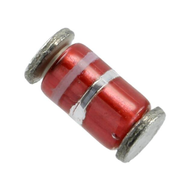
器件简介:这是一系列表面贴装的1.5W Zener二极管,具有与JEDEC注册的1N5913B至1N5956B轴向引线封装相似的电气特性。适用于高密度和低寄生要求的应用。由于其玻璃密封特性和冶金增强的内部接触,当需要时,也可以用于高可靠性应用。
引脚分配:文档中没有明确指出具体的引脚分配,但提到了表面贴装和轴向引线封装两种类型。
参数特性:包括Zener电压范围3.3V至200V,电压容差有10%、5%、2%和1%可选。符合RoHS标准的版本可用。
功能详解:这些Zener二极管可以调节在广泛的操作电流和温度范围内的电压。无引线封装适用于高密度表面贴装。冶金增强的内部接触设计提高了可靠性并降低了热阻。玻璃密封封装,对静电放电不敏感。
应用信息:适用于需要电压调节的场合,特别是在高密度表面贴装和高可靠性要求的应用中。
封装信息:提供DO-213AB MELF封装、DO-41封装、SMB封装、SMAJ封装和Powermite封装。封装尺寸和布局在文档的最后部分提供。