MTCH112 Evaluation Kit
User’s Guide
2014-2015 Microchip Technology Inc.
DS40001773B
�Note the following details of the code protection feature on Microchip devices:
•
Microchip products meet the specification contained in their particular Microchip Data Sheet.
•
Microchip believes that its family of products is one of the most secure families of its kind on the market today, when used in the
intended manner and under normal conditions.
•
There are dishonest and possibly illegal methods used to breach the code protection feature. All of these methods, to our
knowledge, require using the Microchip products in a manner outside the operating specifications contained in Microchip’s Data
Sheets. Most likely, the person doing so is engaged in theft of intellectual property.
•
Microchip is willing to work with the customer who is concerned about the integrity of their code.
•
Neither Microchip nor any other semiconductor manufacturer can guarantee the security of their code. Code protection does not
mean that we are guaranteeing the product as “unbreakable.”
Code protection is constantly evolving. We at Microchip are committed to continuously improving the code protection features of our
products. Attempts to break Microchip’s code protection feature may be a violation of the Digital Millennium Copyright Act. If such acts
allow unauthorized access to your software or other copyrighted work, you may have a right to sue for relief under that Act.
Information contained in this publication regarding device
applications and the like is provided only for your convenience
and may be superseded by updates. It is your responsibility to
ensure that your application meets with your specifications.
MICROCHIP MAKES NO REPRESENTATIONS OR
WARRANTIES OF ANY KIND WHETHER EXPRESS OR
IMPLIED, WRITTEN OR ORAL, STATUTORY OR
OTHERWISE, RELATED TO THE INFORMATION,
INCLUDING BUT NOT LIMITED TO ITS CONDITION,
QUALITY, PERFORMANCE, MERCHANTABILITY OR
FITNESS FOR PURPOSE. Microchip disclaims all liability
arising from this information and its use. Use of Microchip
devices in life support and/or safety applications is entirely at
the buyer’s risk, and the buyer agrees to defend, indemnify and
hold harmless Microchip from any and all damages, claims,
suits, or expenses resulting from such use. No licenses are
conveyed, implicitly or otherwise, under any Microchip
intellectual property rights.
Trademarks
The Microchip name and logo, the Microchip logo, dsPIC,
FlashFlex, flexPWR, JukeBlox, KEELOQ, KEELOQ logo, Kleer,
LANCheck, MediaLB, MOST, MOST logo, MPLAB,
OptoLyzer, PIC, PICSTART, PIC32 logo, RightTouch, SpyNIC,
SST, SST Logo, SuperFlash and UNI/O are registered
trademarks of Microchip Technology Incorporated in the
U.S.A. and other countries.
The Embedded Control Solutions Company and mTouch are
registered trademarks of Microchip Technology Incorporated
in the U.S.A.
Analog-for-the-Digital Age, BodyCom, chipKIT, chipKIT logo,
CodeGuard, dsPICDEM, dsPICDEM.net, ECAN, In-Circuit
Serial Programming, ICSP, Inter-Chip Connectivity, KleerNet,
KleerNet logo, MiWi, MPASM, MPF, MPLAB Certified logo,
MPLIB, MPLINK, MultiTRAK, NetDetach, Omniscient Code
Generation, PICDEM, PICDEM.net, PICkit, PICtail,
RightTouch logo, REAL ICE, SQI, Serial Quad I/O, Total
Endurance, TSHARC, USBCheck, VariSense, ViewSpan,
WiperLock, Wireless DNA, and ZENA are trademarks of
Microchip Technology Incorporated in the U.S.A. and other
countries.
SQTP is a service mark of Microchip Technology Incorporated
in the U.S.A.
Silicon Storage Technology is a registered trademark of
Microchip Technology Inc. in other countries.
GestIC is a registered trademarks of Microchip Technology
Germany II GmbH & Co. KG, a subsidiary of Microchip
Technology Inc., in other countries.
All other trademarks mentioned herein are property of their
respective companies.
© 2014-2015, Microchip Technology Incorporated, Printed in
the U.S.A., All Rights Reserved.
ISBN: 978-1-63277-006-6
QUALITY MANAGEMENT SYSTEM
CERTIFIED BY DNV
== ISO/TS 16949 ==
DS40001773B-page 2
Microchip received ISO/TS-16949:2009 certification for its worldwide
headquarters, design and wafer fabrication facilities in Chandler and
Tempe, Arizona; Gresham, Oregon and design centers in California
and India. The Company’s quality system processes and procedures
are for its PIC® MCUs and dsPIC® DSCs, KEELOQ® code hopping
devices, Serial EEPROMs, microperipherals, nonvolatile memory and
analog products. In addition, Microchip’s quality system for the design
and manufacture of development systems is ISO 9001:2000 certified.
2014-2015 Microchip Technology Inc.
�MTCH112 EVALUATION
KIT USER’S GUIDE
Table of Contents
Preface ........................................................................................................................... 5
Chapter 1. MTCH112 Overview
1.1 Introduction ................................................................................................... 11
1.1.1 Kit Contents ............................................................................................... 11
1.2 Hardware Setup ........................................................................................... 11
1.2.1 MTCH112 Controller Board ....................................................................... 11
1.2.2 MTCH112 Sensor Boards ......................................................................... 12
1.3 MTCH112 GUI .............................................................................................. 13
1.3.1 Sensor Control and Configuration (Area A) ............................................... 15
1.3.2 Input Sensing Output Pin Configuration (Area B) ...................................... 15
1.3.3 Input Sensing System Configuration (Area C) ........................................... 16
1.3.3.1 Sleep Time ................................................................................ 16
1.3.3.2 System Clock ............................................................................. 16
1.3.3.3 Press Threshold ........................................................................ 16
1.3.3.4 Proximity Threshold ................................................................... 16
1.3.3.5 Button-Press Time-Out .............................................................. 16
1.3.3.6 I2C™ Address ............................................................................ 17
1.3.4 Real-Time Sensor Status (Area D) ............................................................ 17
1.3.5 Real-Time Sensor Information (Area E) .................................................... 17
1.3.6 The Plot (Area F) ....................................................................................... 18
1.3.7 Product Reset (Area G) ............................................................................. 18
1.3.8 Application Configuration and Data Log (Area H) ..................................... 19
1.3.8.1 Reading an mTouch™ Configuration ........................................ 19
1.3.8.2 Saving the current mTouch Configuration ................................. 19
1.3.8.3 Logging the Real-Time Data ...................................................... 19
1.3.8.4 Adjusting the Plot Area .............................................................. 20
1.3.9 The Plot Control Area ................................................................................ 21
1.3.9.1 Auto-Scroll Checkbox ................................................................ 21
1.3.9.2 Play Button ................................................................................ 21
1.3.9.3 Playback Speed Slider .............................................................. 21
1.3.9.4 Stop Button ................................................................................ 21
1.3.9.5 Position Slider ............................................................................ 22
1.3.9.6 Print ........................................................................................... 22
Appendix A. MTCH112 Controller Board Schematic
Appendix B. MTCH112 Controller Board Layout
Appendix C. MTCH112 Proximity Sensor Board Layout
Appendix D. MTCH112 Dual Touch Sensor Board Layout
Worldwide Sales and Service .................................................................................... 31
2014-2015 Microchip Technology Inc.
DS40001773B-page 3
�MTCH112 Evaluation Kit User’s Guide
NOTES:
DS40001773B-page 4
2014-2015 Microchip Technology Inc.
�MTCH112 EVALUATION KIT USER’S GUIDE
Preface
NOTICE TO CUSTOMERS
All documentation becomes dated, and this manual is no exception. Microchip tools and
documentation are constantly evolving to meet customer needs, so some actual dialogs
and/or tool descriptions may differ from those in this document. Please refer to our web site
(www.microchip.com) to obtain the latest documentation available.
Documents are identified with a “DS” number. This number is located on the bottom of each
page, in front of the page number. The numbering convention for the DS number is
“DSXXXXXA”, where “XXXXX” is the document number and “A” is the revision level of the
document.
For the most up-to-date information on development tools, see the MPLAB® IDE online help.
Select the Help menu, and then Topics to open a list of available online help files.
INTRODUCTION
This chapter contains general information that will be useful to know before using the
MTCH112 Evaluation Kit. Items discussed in this chapter include:
•
•
•
•
•
•
•
Document Layout
Conventions Used in this Guide
Recommended Reading
The Microchip Web Site
Development Systems Customer Change Notification Service
Customer Support
Revision History
DOCUMENT LAYOUT
This document describes how to use the MTCH112 Evaluation Kit to quickly get started
with Microchip’s Touch Input Sensing technology. The document is organized as
follows:
•
•
•
•
•
Chapter 1. “MTCH112 Overview”
Appendix A. “MTCH112 Controller Board Schematic ”
Appendix B. “MTCH112 Controller Board Layout ”
Appendix C. “MTCH112 Proximity Sensor Board Layout ”
Appendix D. “MTCH112 Dual Touch Sensor Board Layout ”
2014-2015 Microchip Technology Inc.
DS40001773B-page 5
�MTCH112 Evaluation Kit User’s Guide
CONVENTIONS USED IN THIS GUIDE
This manual uses the following documentation conventions:
DOCUMENTATION CONVENTIONS
Description
Arial font:
Italic characters
Initial caps
Quotes
Underlined, italic text with
right angle bracket
Bold characters
N‘Rnnnn
Text in angle brackets < >
Courier New font:
Plain Courier New
Represents
Examples
Referenced books
Emphasized text
A window
A dialog
A menu selection
A field name in a window or
dialog
A menu path
MPLAB® IDE User’s Guide
...is the only compiler...
the Output window
the Settings dialog
select Enable Programmer
“Save project before build”
A dialog button
A tab
A number in verilog format,
where N is the total number of
digits, R is the radix and n is a
digit.
A key on the keyboard
Click OK
Click the Power tab
4‘b0010, 2‘hF1
Italic Courier New
Sample source code
Filenames
File paths
Keywords
Command-line options
Bit values
Constants
A variable argument
Square brackets [ ]
Optional arguments
Curly brackets and pipe
character: { | }
Ellipses...
Choice of mutually exclusive
arguments; an OR selection
Replaces repeated text
Represents code supplied by
user
DS40001773B-page 6
File>Save
Press ,
#define START
autoexec.bat
c:\mcc18\h
_asm, _endasm, static
-Opa+, -Opa0, 1
0xFF, ‘A’
file.o, where file can be
any valid filename
mcc18 [options] file
[options]
errorlevel {0|1}
var_name [,
var_name...]
void main (void)
{ ...
}
2014-2015 Microchip Technology Inc.
�Preface
RECOMMENDED READING
This user’s guide describes how to use Microchip’s MTCH112 Evaluation Kit. Other
useful documents are listed below. The following Microchip documents are available
and recommended as supplemental reference resources.
http://www.microchip.com
MTCH112 Dual-Channel Proximity/Touch Controller Data Sheet (DS41668)
This data sheet provides detailed information regarding the MTCH112.
MTCH112 Dual-Channel Proximity Touch Controller Product Brief (DS41659)
This product brief provides marketing information regarding the MTCH112.
2014-2015 Microchip Technology Inc.
DS40001773B-page 7
�MTCH112 Evaluation Kit User’s Guide
THE MICROCHIP WEB SITE
Microchip provides online support via our web site at www.microchip.com. This web
site is used as a means to make files and information easily available to customers.
Accessible by using your favorite Internet browser, the web site contains the following
information:
• Product Support – Data sheets and errata, application notes and sample
programs, design resources, user’s guides and hardware support documents,
latest software releases and archived software
• General Technical Support – Frequently Asked Questions (FAQs), technical
support requests, online discussion groups, Microchip consultant program
member listing
• Business of Microchip – Product selector and ordering guides, latest Microchip
press releases, listing of seminars and events, listings of Microchip sales offices,
distributors and factory representatives
DEVELOPMENT SYSTEMS CUSTOMER CHANGE NOTIFICATION SERVICE
Microchip’s customer notification service helps keep customers current on Microchip
products. Subscribers will receive e-mail notification whenever there are changes,
updates, revisions or errata related to a specified product family or development tool of
interest.
To register, access the Microchip web site at www.microchip.com, click on Customer
Change Notification and follow the registration instructions.
The Development Systems product group categories are:
• Compilers – The latest information on Microchip C compilers, assemblers, linkers
and other language tools. These include all MPLAB C compilers; all MPLAB
assemblers (including MPASM™ assembler); all MPLAB linkers (including
MPLINK™ object linker); and all MPLAB librarians (including MPLIB™ object
librarian).
• Emulators – The latest information on Microchip in-circuit emulators.This
includes the MPLAB REAL ICE™ and MPLAB ICE 2000 in-circuit emulators.
• In-Circuit Debuggers – The latest information on the Microchip in-circuit
debuggers. This includes MPLAB ICD 3 in-circuit debuggers and PICkit™ 3
debug express.
• MPLAB® IDE – The latest information on Microchip MPLAB IDE, the Windows®
Integrated Development Environment for development systems tools. This list is
focused on the MPLAB IDE, MPLAB IDE Project Manager, MPLAB Editor and
MPLAB SIM simulator, as well as general editing and debugging features.
• Programmers – The latest information on Microchip programmers. These include
production programmers such as MPLAB REAL ICE in-circuit emulator, MPLAB
ICD 3 in-circuit debugger and MPLAB PM3 device programmers. Also included
are nonproduction development programmers such as PICSTART® Plus and
PICkit 2 and 3.
DS40001773B-page 8
2014-2015 Microchip Technology Inc.
�Preface
CUSTOMER SUPPORT
Users of Microchip products can receive assistance through several channels:
•
•
•
•
Distributor or Representative
Local Sales Office
Field Application Engineer (FAE)
Technical Support
Customers should contact their distributor, representative or field application engineer
(FAE) for support. Local sales offices are also available to help customers. A listing of
sales offices and locations is included in the back of this document.
Technical support is available through the web site at:
http://www.microchip.com/support.
REVISION HISTORY
Revision A (October 2014)
Initial release of this document.
Revision B (January 2015)
Updated Figure A-1; Other minor corrections.
2014-2015 Microchip Technology Inc.
DS40001773B-page 9
�MTCH112 Evaluation Kit User’s Guide
NOTES:
DS40001773B-page 10
2014-2015 Microchip Technology Inc.
�MTCH112 EVALUATION KIT USER’S GUIDE
Chapter 1. MTCH112 Overview
1.1
INTRODUCTION
The MTCH112 Evaluation Kit allows the user to implement up to two Touch and/or Proximity input channels
very quickly with many options to tune the MTCH112 device to meet user application requirements. The user
can alter multiple internal parameters that affect the chip’s sensitivity, response time, power consumption,
and behavior.
1.1.1
•
•
•
•
Kit Contents
MTCH112 Controller Board
MTCH112 Touch-Button Sensor Board
MTCH112 Proximity Sensor Board
Mini to USB-B Cable
1.2
HARDWARE SETUP
Before using the board, it is necessary to connect some of the hardware elements included in the kit.
Described below are the hardware items required to correctly operate the board.
1.2.1
MTCH112 Controller Board
FIGURE 1-1:
MTCH112 MOTHERBOARD
Figure 1-1 shows the main board with the MTCH112 chip (U1 Chip on board). It handles every aspect of the
touch input process. It expects a capacitive touch sensor on the female 12-pin header connector to the right
of the U1 chip. Either of the sensor boards included in the package can be connected to the controller board.
Alternatively, the user can connect up to two sensors to the pins labeled I0 and I1 on the PCB.
DS40001773B-page 11
2014-2015 Microchip Technology Inc.
�MTCH112 Evaluation Kit User’s Guide
To the left of the U1 chip, the board has a 6-pin header connector labeled ‘Comm Interface’, mainly used to
allow the input sensing application to communicate with a host system. The connector’s pins are assigned
to accommodate PICKit™ Serial Analyzer communications (Figure 1-2). This feature allows the board not
only to report its sensor state information in real time, but to be controlled and configured by a host device
at any time. The MTCH112 and the evaluation board use I2C™ protocol involving only two signals (SCL and
SDA, as highlighted below). For a full set of I2C commands and related timings, please refer to the
MTCH112 data sheet (DS41668) at www.microchip.com/mtch112.
FIGURE 1-2:
PICKit™ SERIAL ANALYZER CONNECTOR PIN MAPPING
The MTCH112 Evaluation Board can be powered by applying 3.3V to pin 2 of the communication connector,
or by connecting an already powered USB cable.
Once it is powered, the board is operational. This can be easily checked by connecting one of the sensor
boards and directly touching a sensor. A touch should light the red LED (D1) on the controller board.
1.2.2
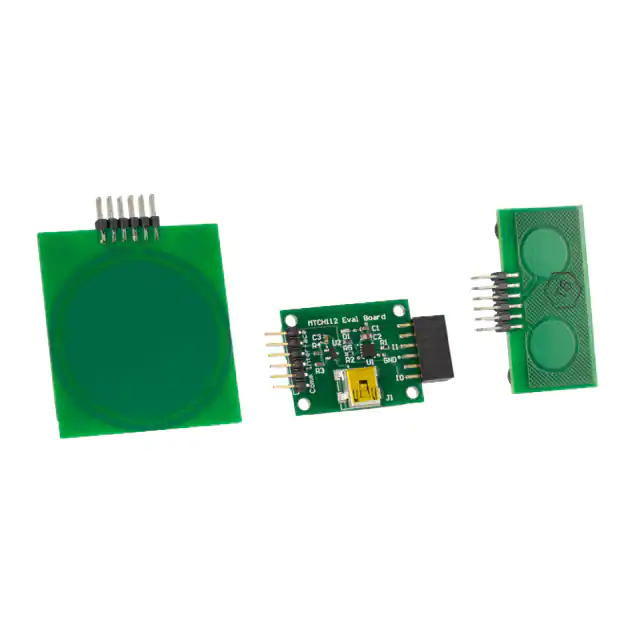
MTCH112 Sensor Boards
The Evaluation Kit comes with one Touch (with two sensors) daughter board (below left) and one proximity
sensor daughter board (below right) as shown in Figure 1-3.
FIGURE 1-3:
MTCH112 KIT SENSOR BOARDS
The Proximity sensor board has a built-in guard ring that can be driven by the MTCH112 controller to maximize the sensitivity.
DS40001773B-page 12
2014-2015 Microchip Technology Inc.
�MTCH112 Overview
FIGURE 1-4:
PICKit™ SERIAL ANALYZER
The optional PICKit Serial Communication interface (Figure 1-4) is not part of the evaluation kit. It is sold
separately and available on microchipDIRECT (DV164122). This communication interface device becomes
necessary when the MTCH112 Windows® GUI is used. The PICKit Serial Analyzer allows bridging I2C (and
more) to USB, a popular communication hardware to personal computers in general and PC/Windows in
particular.
The PICKit Serial Analyzer should be connected on one end to the 6-pin header connector of the MTCH112
controller board, and the other end to a USB port of a Windows computer.
With all these items connected, the board should be fully operational and ready to communicate with the
Windows-based MTCH112 GUI.
1.3
MTCH112 GUI
After installing and running Microchip’s MTCH112 GUI, the user is presented with power setting options
(Figure 1-5) if the controller board is not yet powered through the USB connector.
FIGURE 1-5:
MTCH112 EVALUATION KIT GUI POWER OPTION
2014-2015 Microchip Technology Inc.
DS40001773B-page 13
�MTCH112 Evaluation Kit User’s Guide
Move the slider so that it selects 3.3V and click Apply. This will start the GUI and the application’s main
window will appear as shown below (see Figure 1-6).
FIGURE 1-6:
MTCH112 GUI MAIN WINDOW
The GUI window can be divided into nine functional areas identified A through I, as shown below in
Figure 1-7.
FIGURE 1-7:
DS40001773B-page 14
MTCH112 GUI FUNCTIONAL AREAS
2014-2015 Microchip Technology Inc.
�MTCH112 Overview
A: Sensor Control and Configuration
B: Input Sensing Output Pin Configuration
C: Input Sensing System Configuration
D: Real-Time Sensor Status
E: Real-Time Sensor Information
F: Plot Area
G: Product Reset Area
H: GUI Miscellaneous (storage and configuration)
I: Plot Control
1.3.1
Sensor Control and Configuration (Area A)
FIGURE 1-8:
SENSOR CONTROL AND CONFIGURATION AREA (A)
This area specifies whether the MTCH112 controller is managing a single sensor (default sensor 0) or two
by enabling or disabling sensor 1, respectively.
A calibration of each sensor can be started using the Calibration checkbox. The system shows ‘Completed’
once the calibration of the controller is complete.
The MTCH112 controller automatically selects the acquisition waveform type during the calibration process
and notifies the GUI.
1.3.2
Input Sensing Output Pin Configuration (Area B)
FIGURE 1-9:
INPUT SENSING OUTPUT PIN CONFIGURATION (B)
The MTCH112 controller uses a single interrupt output pin to notify the host about the detection of a new
event on one or more of its sensors. This area allows the user to specify which events the MTCH112 controller generates notification about.
Once the host system gets the new event detection notification, an I2C command should be issued to read
the button state mask, which provides what event type and which sensor generated the event.
2014-2015 Microchip Technology Inc.
DS40001773B-page 15
�MTCH112 Evaluation Kit User’s Guide
1.3.3
Input Sensing System Configuration (Area C)
FIGURE 1-10:
INPUT SENSING SYSTEM CONFIGURATION AREA (C)
This area allows the user to interact with the system parameters which affect the way Touch Input Sensing
behaves. Following is a list of parameters controlled by this area.
1.3.3.1
SLEEP TIME
This control specifies the time between two scans. This directly affects the application power consumption
and response time. The user can choose a value from 1 millisecond to 256 seconds Sleep Time.
1.3.3.2
SYSTEM CLOCK
The user can set the controller’s main clock to either 16 MHz or 32 MHz, depending on whether the
application primarily requires performance (32 MHz) or lower power consumption (16 MHz).
1.3.3.3
PRESS THRESHOLD
When a sensor is used as a button, the user can specify the minimum value for the readings beyond which
the MTCH112 controller considers that the button is in the Pressed state. One way to determine a good
value for the threshold is to perform a few touches and check the maximum value of the shift (Area E). The
threshold can be set to a percentage of the maximum shift.
Another parameter that should be considered when setting the threshold value is the noise level. The
threshold value should be set above the highest level of noise to avoid false button triggers due to noise.
1.3.3.4
PROXIMITY THRESHOLD
Same as above, but for Proximity detection.
1.3.3.5
BUTTON-PRESS TIME-OUT
When a button is detected as pressed, the system uses a time-out mechanism before forcing this button to
a Released state, in case the button is pressed for too long. This feature helps prevent stuck buttons. Setting 0 instructs the application to never time out.
DS40001773B-page 16
2014-2015 Microchip Technology Inc.
�MTCH112 Overview
1.3.3.6
I2C™ ADDRESS
The MTCH112 controller uses I2C protocol (and bus) to communicate with a host controller. In the case
where multiple MTCH112 controllers are used in the same system, or the MTCH112 is used on an I2C bus
where its slave address is already assigned to another device, the user has the ability to assign a new I2C
address to the MTCH112 to avoid any conflict. This is done by specifying a new hexadecimal value in this
control box.
1.3.4
Real-Time Sensor Status (Area D)
FIGURE 1-11:
REAL-TIME SENSOR STATUS AREA (D)
This area depicts the actual state of the active sensors managed by the MTCH112 controller, using colored
buttons.
The absence of any button indicates its Released state.
A Green button shows an actual Press.
A Yellow button shows a Proximity detection event.
Any other type of button shown would mean a problem with the sensor (e.g., shorted) or an unrecognized
state.
1.3.5
Real-Time Sensor Information (Area E)
FIGURE 1-12:
REAL-TIME SENSOR INFORMATION AREA (E)
For each active sensor, this area displays the latest raw value, current baseline value (which reflects the
environment), and keeps track of the highest raw value observed since the start of the application or the
maximum values were reset.
The last control button on the far right side of this area resets the maximum raw values recorded to date.
The system will then start tracking the next maximum value it sees.
2014-2015 Microchip Technology Inc.
DS40001773B-page 17
�MTCH112 Evaluation Kit User’s Guide
1.3.6
The Plot (Area F)
This section of the GUI is responsible for acquiring the real-time data sent by the MTCH112 controller, and
representing it as a continuous plot allowing the user to easily track any change on the sensors’ signals.
The red line represents Sensor0’s signal and the green line represents Sensor1’s signal.
The dotted graph lines (with the same color convention) track each sensor’s baseline over time.
FIGURE 1-13:
1.3.7
GUI PLOT AREA (F)
Product Reset (Area G)
FIGURE 1-14:
PRODUCT RESET AREA (G)
Touch systems can get very complex based on the number of parameters they involve in order to get them
to operate at their optimum performance. Each parameter can have significant impact on the system’s performance.
The GUI allows the user to reset the system to its factory configuration by clicking the control button shown
above.
DS40001773B-page 18
2014-2015 Microchip Technology Inc.
�MTCH112 Overview
1.3.8
Application Configuration and Data Log (Area H)
FIGURE 1-15:
APPLICATION AND DATA LOG AREA (H)
This area provides four buttons for control of miscellaneous functions for the GUI and the Input Sensing
application. The button functions will be considered from left to right.
1.3.8.1
READING AN mTouch™ CONFIGURATION
FIGURE 1-16:
RECALLING A PREVIOUSLY SAVED CONFIGURATION
The user has the ability to save all parameters at any time and recall from the computer’s Hard Disk Drive
(HDD) and set them into the MTCH112 controller.
1.3.8.2
SAVING THE CURRENT mTouch CONFIGURATION
FIGURE 1-17:
SAVING CURRENT mTouch™ CONFIGURATION
This button saves all current parameter values to the computer’s hard drive.
1.3.8.3
LOGGING THE REAL-TIME DATA
FIGURE 1-18:
LOGGING REAL-TIME DATA
In some cases, in order to track the Input System’s performance, a significant amount of information is
required. The GUI offers to save all sensor data in an Excel File format (CSV) for easy data analysis.
The button shown above, when pressed, will open the following window, expecting the user to make a few
choices before starting the data recording.
2014-2015 Microchip Technology Inc.
DS40001773B-page 19
�MTCH112 Evaluation Kit User’s Guide
FIGURE 1-19:
REAL-TIME LOG CONFIGURATION
The user can specify a CSV file name and location, required to start the recording process using the
checkbox at the top of the window.
When the user presses the Done button, the window closes and the recording starts and runs in the background.
The user can then at any time press this button again and simply deselect the checkbox at the top (which
should read ‘Running’) to stop the recording process and access the Excel file for analysis.
1.3.8.4
ADJUSTING THE PLOT AREA
FIGURE 1-20:
ZOOMING INTO AND OUT OF THE PLOT AREA
Zooming in and out of the graph representation of the data can be performed using the button shown above.
When clicked, the GUI grants the user with the following window where the zooming range can be set.
FIGURE 1-21:
ZOOM SETTINGS
The X-values basically specify how many Raw Data samples are graphed in the visible area. The values
above show that the GUI is displaying the values of 1000 samples at any time. It also shows that it is displaying samples from 0 to 1000.
The Y-values simply specify which range of data will be taken into account for display. The values shown
above instruct the plot window to only display Raw Readings between 600 and 16000 counts.
The user can finally either activate these values by pressing ‘Set’ or ignore them and keep whichever values
the GUI was previously using by pressing ‘Forget’.
DS40001773B-page 20
2014-2015 Microchip Technology Inc.
�MTCH112 Overview
1.3.9
The Plot Control Area
At the top of the plot area a grey toolbar allows control of how the plotter behaves. Below is a description of
the different buttons.
FIGURE 1-22:
1.3.9.1
AUTO-SCROLL CHECKBOX
In reality, two different types of controls allow interaction with the scrolling: The Autoscroll checkbox and
the Play button.
FIGURE 1-23:
THE AUTO-SCROLL CHECKBOX
The Auto-scroll checkbox, which activates and de-activates the automatic calculation of the scrolling speed
(which depends on the rate at which the data gets to the GUI), allows the plot window to keep up with the
latest data to be plotted at the right side of the plot area.
When Auto-scroll is unchecked, the plot window will keep scrolling, at the speed set by the ‘Playback
Speed’ slider.
1.3.9.2
PLAY BUTTON
FIGURE 1-24:
THE PLAY BUTTON
This button enables the scrolling of the display. It reads the speed value set by the ‘Playback Speed’ slider
and starts the scrolling through the data from the current position and to the right of the display.
1.3.9.3
PLAYBACK SPEED SLIDER
FIGURE 1-25:
THE PLAYBACK SPEED SLIDER
This slider controls the speed at which the graphed data is browsed. The Play button will use the value set
by this control to scroll through the received data.
1.3.9.4
STOP BUTTON
FIGURE 1-26:
THE STOP BUTTON
When pressed and Auto-scroll is disabled, this button stops the scrolling.
2014-2015 Microchip Technology Inc.
DS40001773B-page 21
�MTCH112 Evaluation Kit User’s Guide
1.3.9.5
POSITION SLIDER
FIGURE 1-27:
THE BROWSING POSITION SLIDER
This slider allows the user to rapidly browse through the received data. The plot window keeps track of all
the readings received since the application was started. The graphs can be recalled or checked by stopping
the scrolling and browsing with either the Position slider or using the mouse pointer by clicking and holding
while scrolling.
1.3.9.6
PRINT
FIGURE 1-28:
PRINTING THE GRAPHS
This button sends the visible part of the graphs to a Windows® printer.
DS40001773B-page 22
2014-2015 Microchip Technology Inc.
�DS40001773B-page 23
GND
VDD
R3
3.3k
VDD
440247-2
SDA
SCL
MTO
RESET
R4
3.3K
GND
5
1
2
3
4
SCL
SDA
VIN
U2
VOUT
2
Header 6H
1
2
3
4
5
6
P2
C1
Cap
0.1 uF
GND
VDD
C3
1
GND
Cap
1 uF
MCP1700T-3302E/TT
3
RESET
MTI0
MTO
VDD
C2
Cap
1 uF
4
3
2
1
VSS
MTCH112
RESET
MTI0
SDA
SCL
MTO/INT MTI1/MTGRD0
U1
VDD
GND
VDD
5
6
7
8
SDA
SCL
MTI1
GND
GND
4.7K
MTI0 R2
MTI1 R1
4.7K
MTO
7
8
9
10
11
12
1K
R5
Header 6X2A
1
2
3
4
5
6
P1
VDD
D1
LED1
FIGURE A-1:
SHLD
J1
VBUS
DD+
GND
MTCH112 EVALUATION KIT USER’S GUIDE
Appendix A. MTCH112 Controller Board Schematic
MTCH112 CONTROLLER BOARD SCHEMATIC
2014-2015 Microchip Technology Inc.
�MTCH112 Evaluation Kit User’s Guide
NOTES:
DS40001773B-page 24
2014-2015 Microchip Technology Inc.
�MTCH112 EVALUATION KIT USER’S GUIDE
Appendix B. MTCH112 Controller Board Layout
FIGURE B-1:
2014-2015 Microchip Technology Inc.
MTCH112 CONTROLLER BOARD LAYOUT
DS40001773B-page 25
�MTCH112 Evaluation Kit User’s Guide
NOTES:
DS40001773B-page 26
2014-2015 Microchip Technology Inc.
�MTCH112 EVALUATION KIT USER’S GUIDE
Appendix C. MTCH112 Proximity Sensor Board Layout
FIGURE C-1:
DS40001773B-page 27
MTCH112 PROXIMITY SENSOR BOARD LAYOUT
2014-2015 Microchip Technology Inc.
�MTCH112 Evaluation Kit User’s Guide
NOTES:
DS40001773B-page 28
2014-2015 Microchip Technology Inc.
�MTCH112 EVALUATION KIT USER’S GUIDE
Appendix D. MTCH112 Dual Touch Sensor Board Layout
FIGURE D-1:
2014-2015 Microchip Technology Inc.
MTCH112 DUAL TOUCH SENSOR BOARD LAYOUT
DS40001773B-page 29
�MTCH112 Evaluation Kit User’s Guide
NOTES:
DS40001773B-page 30
2014-2015 Microchip Technology Inc.
�Worldwide Sales and Service
AMERICAS
ASIA/PACIFIC
ASIA/PACIFIC
EUROPE
Corporate Office
2355 West Chandler Blvd.
Chandler, AZ 85224-6199
Tel: 480-792-7200
Fax: 480-792-7277
Technical Support:
http://www.microchip.com/
support
Web Address:
www.microchip.com
Asia Pacific Office
Suites 3707-14, 37th Floor
Tower 6, The Gateway
Harbour City, Kowloon
Hong Kong
Tel: 852-2943-5100
Fax: 852-2401-3431
China - Xiamen
Tel: 86-592-2388138
Fax: 86-592-2388130
China - Zhuhai
Tel: 86-756-3210040
Fax: 86-756-3210049
Austria - Wels
Tel: 43-7242-2244-39
Fax: 43-7242-2244-393
Denmark - Copenhagen
Tel: 45-4450-2828
Fax: 45-4485-2829
India - Bangalore
Tel: 91-80-3090-4444
Fax: 91-80-3090-4123
France - Paris
Tel: 33-1-69-53-63-20
Fax: 33-1-69-30-90-79
India - New Delhi
Tel: 91-11-4160-8631
Fax: 91-11-4160-8632
Germany - Dusseldorf
Tel: 49-2129-3766400
Australia - Sydney
Tel: 61-2-9868-6733
Fax: 61-2-9868-6755
Atlanta
Duluth, GA
Tel: 678-957-9614
Fax: 678-957-1455
China - Beijing
Tel: 86-10-8569-7000
Fax: 86-10-8528-2104
Austin, TX
Tel: 512-257-3370
China - Chengdu
Tel: 86-28-8665-5511
Fax: 86-28-8665-7889
Boston
Westborough, MA
Tel: 774-760-0087
Fax: 774-760-0088
Chicago
Itasca, IL
Tel: 630-285-0071
Fax: 630-285-0075
Cleveland
Independence, OH
Tel: 216-447-0464
Fax: 216-447-0643
China - Chongqing
Tel: 86-23-8980-9588
Fax: 86-23-8980-9500
China - Dongguan
Tel: 86-769-8702-9880
China - Hangzhou
Tel: 86-571-8792-8115
Fax: 86-571-8792-8116
India - Pune
Tel: 91-20-3019-1500
Japan - Osaka
Tel: 81-6-6152-7160
Fax: 81-6-6152-9310
Japan - Tokyo
Tel: 81-3-6880- 3770
Fax: 81-3-6880-3771
Korea - Daegu
Tel: 82-53-744-4301
Fax: 82-53-744-4302
China - Hong Kong SAR
Tel: 852-2943-5100
Fax: 852-2401-3431
Korea - Seoul
Tel: 82-2-554-7200
Fax: 82-2-558-5932 or
82-2-558-5934
China - Nanjing
Tel: 86-25-8473-2460
Fax: 86-25-8473-2470
Malaysia - Kuala Lumpur
Tel: 60-3-6201-9857
Fax: 60-3-6201-9859
Detroit
Novi, MI
Tel: 248-848-4000
China - Qingdao
Tel: 86-532-8502-7355
Fax: 86-532-8502-7205
Malaysia - Penang
Tel: 60-4-227-8870
Fax: 60-4-227-4068
Houston, TX
Tel: 281-894-5983
China - Shanghai
Tel: 86-21-5407-5533
Fax: 86-21-5407-5066
Philippines - Manila
Tel: 63-2-634-9065
Fax: 63-2-634-9069
China - Shenyang
Tel: 86-24-2334-2829
Fax: 86-24-2334-2393
Singapore
Tel: 65-6334-8870
Fax: 65-6334-8850
China - Shenzhen
Tel: 86-755-8864-2200
Fax: 86-755-8203-1760
Taiwan - Hsin Chu
Tel: 886-3-5778-366
Fax: 886-3-5770-955
China - Wuhan
Tel: 86-27-5980-5300
Fax: 86-27-5980-5118
Taiwan - Kaohsiung
Tel: 886-7-213-7828
Dallas
Addison, TX
Tel: 972-818-7423
Fax: 972-818-2924
Indianapolis
Noblesville, IN
Tel: 317-773-8323
Fax: 317-773-5453
Los Angeles
Mission Viejo, CA
Tel: 949-462-9523
Fax: 949-462-9608
New York, NY
Tel: 631-435-6000
San Jose, CA
Tel: 408-735-9110
Canada - Toronto
Tel: 905-673-0699
Fax: 905-673-6509
China - Xian
Tel: 86-29-8833-7252
Fax: 86-29-8833-7256
Germany - Munich
Tel: 49-89-627-144-0
Fax: 49-89-627-144-44
Germany - Pforzheim
Tel: 49-7231-424750
Italy - Milan
Tel: 39-0331-742611
Fax: 39-0331-466781
Italy - Venice
Tel: 39-049-7625286
Netherlands - Drunen
Tel: 31-416-690399
Fax: 31-416-690340
Poland - Warsaw
Tel: 48-22-3325737
Spain - Madrid
Tel: 34-91-708-08-90
Fax: 34-91-708-08-91
Sweden - Stockholm
Tel: 46-8-5090-4654
UK - Wokingham
Tel: 44-118-921-5800
Fax: 44-118-921-5820
Taiwan - Taipei
Tel: 886-2-2508-8600
Fax: 886-2-2508-0102
Thailand - Bangkok
Tel: 66-2-694-1351
Fax: 66-2-694-1350
01/27/15
2014-2015 Microchip Technology Inc.
DS40001773B-page 31
�