dsPIC33EV 5V CAN-LIN
Starter Kit User’s Guide
2014 Microchip Technology Inc.
DS50002311A
�Note the following details of the code protection feature on Microchip devices:
•
Microchip products meet the specification contained in their particular Microchip Data Sheet.
•
Microchip believes that its family of products is one of the most secure families of its kind on the market today, when used in the
intended manner and under normal conditions.
•
There are dishonest and possibly illegal methods used to breach the code protection feature. All of these methods, to our
knowledge, require using the Microchip products in a manner outside the operating specifications contained in Microchip’s Data
Sheets. Most likely, the person doing so is engaged in theft of intellectual property.
•
Microchip is willing to work with the customer who is concerned about the integrity of their code.
•
Neither Microchip nor any other semiconductor manufacturer can guarantee the security of their code. Code protection does not
mean that we are guaranteeing the product as “unbreakable.”
Code protection is constantly evolving. We at Microchip are committed to continuously improving the code protection features of our
products. Attempts to break Microchip’s code protection feature may be a violation of the Digital Millennium Copyright Act. If such acts
allow unauthorized access to your software or other copyrighted work, you may have a right to sue for relief under that Act.
Information contained in this publication regarding device
applications and the like is provided only for your convenience
and may be superseded by updates. It is your responsibility to
ensure that your application meets with your specifications.
MICROCHIP MAKES NO REPRESENTATIONS OR
WARRANTIES OF ANY KIND WHETHER EXPRESS OR
IMPLIED, WRITTEN OR ORAL, STATUTORY OR
OTHERWISE, RELATED TO THE INFORMATION,
INCLUDING BUT NOT LIMITED TO ITS CONDITION,
QUALITY, PERFORMANCE, MERCHANTABILITY OR
FITNESS FOR PURPOSE. Microchip disclaims all liability
arising from this information and its use. Use of Microchip
devices in life support and/or safety applications is entirely at
the buyer’s risk, and the buyer agrees to defend, indemnify and
hold harmless Microchip from any and all damages, claims,
suits, or expenses resulting from such use. No licenses are
conveyed, implicitly or otherwise, under any Microchip
intellectual property rights.
Trademarks
The Microchip name and logo, the Microchip logo, dsPIC,
FlashFlex, flexPWR, JukeBlox, KEELOQ, KEELOQ logo, Kleer,
LANCheck, MediaLB, MOST, MOST logo, MPLAB,
OptoLyzer, PIC, PICSTART, PIC32 logo, RightTouch, SpyNIC,
SST, SST Logo, SuperFlash and UNI/O are registered
trademarks of Microchip Technology Incorporated in the
U.S.A. and other countries.
The Embedded Control Solutions Company and mTouch are
registered trademarks of Microchip Technology Incorporated
in the U.S.A.
Analog-for-the-Digital Age, BodyCom, chipKIT, chipKIT logo,
CodeGuard, dsPICDEM, dsPICDEM.net, ECAN, In-Circuit
Serial Programming, ICSP, Inter-Chip Connectivity, KleerNet,
KleerNet logo, MiWi, MPASM, MPF, MPLAB Certified logo,
MPLIB, MPLINK, MultiTRAK, NetDetach, Omniscient Code
Generation, PICDEM, PICDEM.net, PICkit, PICtail,
RightTouch logo, REAL ICE, SQI, Serial Quad I/O, Total
Endurance, TSHARC, USBCheck, VariSense, ViewSpan,
WiperLock, Wireless DNA, and ZENA are trademarks of
Microchip Technology Incorporated in the U.S.A. and other
countries.
SQTP is a service mark of Microchip Technology Incorporated
in the U.S.A.
Silicon Storage Technology is a registered trademark of
Microchip Technology Inc. in other countries.
GestIC is a registered trademarks of Microchip Technology
Germany II GmbH & Co. KG, a subsidiary of Microchip
Technology Inc., in other countries.
All other trademarks mentioned herein are property of their
respective companies.
© 2014, Microchip Technology Incorporated, Printed in the
U.S.A., All Rights Reserved.
ISBN: 978-1-63276-749-3
QUALITY MANAGEMENT SYSTEM
CERTIFIED BY DNV
== ISO/TS 16949 ==
DS50002311A-page 2
Microchip received ISO/TS-16949:2009 certification for its worldwide
headquarters, design and wafer fabrication facilities in Chandler and
Tempe, Arizona; Gresham, Oregon and design centers in California
and India. The Company’s quality system processes and procedures
are for its PIC® MCUs and dsPIC® DSCs, KEELOQ® code hopping
devices, Serial EEPROMs, microperipherals, nonvolatile memory and
analog products. In addition, Microchip’s quality system for the design
and manufacture of development systems is ISO 9001:2000 certified.
2014 Microchip Technology Inc.
�Object of Declaration: dsPIC33EV 5V CAN-LIN Starter Kit (DM33018)
2014 Microchip Technology Inc.
DS50002311A-page 3
�Digital Power Starter Kit User’s Guide
NOTES:
DS50002311A-page 4
2014 Microchip Technology Inc.
�dsPIC33EV 5V
CAN-LIN STARTER KIT
USER’S GUIDE
Table of Contents
Preface ........................................................................................................................... 7
Chapter 1. Introduction to the Starter Kit
1.1 Overview ...................................................................................................... 13
1.2 What’s In The Kit .......................................................................................... 14
1.3 Starter Kit Hardware ..................................................................................... 14
1.4 Installing Device Drivers for the Starter Kit ................................................... 17
Chapter 2. The Demonstration Application
2.1 Transmit/Master Mode ................................................................................. 19
2.2 Receive/Slave Mode .................................................................................... 25
2.3 UART Monitoring Log ................................................................................... 25
Chapter 3. Modifying the Application
3.1 Removing CAN from the Demo Application ................................................. 28
Chapter 4. Troubleshooting
Appendix A. Starter Kit Schematics .......................................................................... 31
Index ............................................................................................................................. 35
Worldwide Sales and Service .................................................................................... 36
2014 Microchip Technology Inc.
DS50002311A-page 5
�dsPIC33EV 5V CAN-LIN Starter Kit User’s Guide
DS50002311A-page 6
2014 Microchip Technology Inc.
�dsPIC33EV 5V
CAN-LIN STARTER KIT
USER’S GUIDE
Preface
NOTICE TO CUSTOMERS
All documentation becomes dated, and this manual is no exception. Microchip tools and
documentation are constantly evolving to meet customer needs, so some actual dialogs
and/or tool descriptions may differ from those in this document. Please refer to our web site
(www.microchip.com) to obtain the latest documentation available.
Documents are identified with a “DS” number. This number is located on the bottom of each
page, in front of the page number. The numbering convention for the DS number is
“DSXXXXXA”, where “XXXXX” is the document number and “A” is the revision level of the
document.
For the most up-to-date information on development tools, see the MPLAB® IDE online help.
Select the Help menu, and then Topics to open a list of available online help files.
INTRODUCTION
This chapter contains general information that will be useful to know before using the
dsPIC33EV 5V CAN-LIN Starter Kit. Items discussed in this chapter include:
•
•
•
•
•
•
•
•
Document Layout
Conventions Used in this Guide
Warranty Registration
Recommended Reading
The Microchip Web Site
Development Systems Customer Change Notification Service
Customer Support
Revision History
DOCUMENT LAYOUT
This document describes how to use the dsPIC33EV 5V CAN-LIN Starter Kit as a
development tool to emulate and debug firmware on a target board, as well as how to
program devices. The document is organized as follows:
• Chapter 1. “Introduction to the Starter Kit” provides a brief overview and
hardware description of the Starter Kit.
• Chapter 2. “The Demonstration Application” describes the Starter Kit’s
pre-programmed application.
• Chapter 3. “Modifying the Application” describes how to use the MPLAB® X
IDE to make changes to the demo application
• Chapter 4. “Troubleshooting” describes common issues and their solutions.
• Appendix A. “Starter Kit Schematics” provides detailed schematics for the
Starter Kit.
2014 Microchip Technology Inc.
DS50002311A-page 7
�dsPIC33EV 5V CAN-LIN Starter Kit User’s Guide
CONVENTIONS USED IN THIS GUIDE
This manual uses the following documentation conventions:
DOCUMENTATION CONVENTIONS
Description
Arial font:
Italic characters
Represents
Referenced books
Emphasized text
A window
A dialog
A menu selection
A field name in a window or
dialog
A menu path
MPLAB® IDE User’s Guide
...is the only compiler...
the Output window
the Settings dialog
select Enable Programmer
“Save project before build”
A dialog button
A tab
A key on the keyboard
Click OK
Click the Power tab
Press ,
Italic Courier New
Sample source code
Filenames
File paths
Keywords
Command-line options
Bit values
Constants
A variable argument
Square brackets [ ]
Optional arguments
Curly brackets and pipe
character: { | }
Ellipses...
Choice of mutually exclusive
arguments; an OR selection
Replaces repeated text
#define START
autoexec.bat
c:\mcc18\h
_asm, _endasm, static
-Opa+, -Opa0, 1
0xFF, ‘A’
file.o, where file can be
any valid filename
mcc18 [options] file
[options]
errorlevel {0|1}
Initial caps
Quotes
Underlined, italic text with
right angle bracket
Bold characters
Text in angle brackets < >
Courier New font:
Plain Courier New
Represents code supplied by
user
DS50002311A-page 8
Examples
File>Save
var_name [,
var_name...]
void main (void)
{ ...
}
2014 Microchip Technology Inc.
�Preface
WARRANTY REGISTRATION
Please complete the enclosed Warranty Registration Card and mail it promptly.
Sending in the Warranty Registration Card entitles users to receive new product
updates. Interim software releases are available at the Microchip web site.
RECOMMENDED READING
This user's guide describes how to use dsPIC33EV 5V CAN-LIN Starter Kit. Other useful documents are listed below. The following Microchip documents are available and
recommended as supplemental reference resources.
Readme Files
For the latest information on using other tools, read the tool-specific Readme files in
the Readmes subdirectory of the MPLAB X IDE installation directory. The Readme files
contain update information and known issues that may not be included in this user’s
guide.
dsPIC33 Family Reference Manuals
This reference manuals explain the operation of the dsPIC33 digital signal controller
family architecture and peripheral modules. The specifics of each device family are discussed in the individual family’s device data sheet.
This useful manual is on-line in sections at the Technical Documentation section of the
Microchip website. Refer to these for detailed information on dsPIC33 device operation.
dsPIC33EVXXXGM00X/10X Family Data Sheet (DS70005144) and
dsPIC33EVXXXGM00X/10X Flash Programming Specification (DS70005137)
Refer to this device data sheet for device-specific information and specifications. Also,
refer to the appropriate device flash programming specification for information on
instruction sets and firmware development. These files may be found on the Microchip
website or from your local sales office.
MPLAB® XC16 C Compiler User’s Guide and Libraries (DS50002071)
This document describes the usage of Microchip’s MPLAB XC16 C Compiler for
application development.
MPLAB® X IDE User’s Guide (DS50002027)
This document describes how to use the MPLAB X IDE, Microchip’s latest version of
its integrated development environment, as well as the MPLAB Project Manager,
MPLAB Editor and MPLAB SIM Simulator. Use these development tools to help you
develop and debug application code.
2014 Microchip Technology Inc.
DS50002311A-page 9
�dsPIC33EV 5V CAN-LIN Starter Kit User’s Guide
THE MICROCHIP WEB SITE
Microchip provides online support via our web site at www.microchip.com. This web
site is used as a means to make files and information easily available to customers.
Accessible by using your favorite Internet browser, the web site contains the following
information:
• Product Support – Data sheets and errata, application notes and sample
programs, design resources, user’s guides and hardware support documents,
latest software releases and archived software
• General Technical Support – Frequently Asked Questions (FAQs), technical
support requests, online discussion groups, Microchip consultant program
member listing
• Business of Microchip – Product selector and ordering guides, latest Microchip
press releases, listing of seminars and events, listings of Microchip sales offices,
distributors and factory representatives
DEVELOPMENT SYSTEMS CUSTOMER CHANGE NOTIFICATION SERVICE
Microchip’s customer notification service helps keep customers current on Microchip
products. Subscribers will receive e-mail notification whenever there are changes,
updates, revisions or errata related to a specified product family or development tool of
interest.
To register, access the Microchip web site at www.microchip.com, click on Customer
Change Notification and follow the registration instructions.
The Development Systems product group categories are:
• Compilers – The latest information on Microchip C compilers, assemblers, linkers
and other language tools. These include all MPLAB C compilers; all MPLAB
assemblers (including MPASM™ assembler); all MPLAB linkers (including
MPLINK™ object linker); and all MPLAB librarians (including MPLIB™ object
librarian).
• Emulators – The latest information on Microchip in-circuit emulators.
• In-Circuit Debuggers – The latest information on the Microchip in-circuit
debuggers. This includes MPLAB ICD 3 and PICkit 3 debuggers.
• MPLAB® X IDE – The latest information on Microchip MPLAB X IDE development
environment for all PIC® MCUs. MPLAB X IDE is available for Windows, iOS and
Linux operating systems.
• Programmers – The latest information on Microchip programmers, including the
PM3 production-volume device programmer.
DS50002311A-page 10
2014 Microchip Technology Inc.
�Preface
CUSTOMER SUPPORT
Users of Microchip products can receive assistance through several channels:
•
•
•
•
Distributor or Representative
Local Sales Office
Field Application Engineer (FAE)
Technical Support
Customers should contact their distributor, representative or field application engineer
(FAE) for support. Local sales offices are also available to help customers. A listing of
sales offices and locations is included in the back of this document.
Technical support is available through the web site at:
http://www.microchip.com/support.
REVISION HISTORY
Revision A (October 2014)
This is the initial release of this document.
2014 Microchip Technology Inc.
DS50002311A-page 11
�dsPIC33EV 5V CAN-LIN Starter Kit User’s Guide
NOTES:
DS50002311A-page 12
2014 Microchip Technology Inc.
�dsPIC33EV 5V
CAN-LIN STARTER KIT
USER’S GUIDE
Chapter 1. Introduction to the Starter Kit
Thank you for purchasing the dsPIC33EV 5V CAN-LIN Starter Kit. This board features
the dsPIC33EV256GM106 Digital Signal Controller (DSC) for automotive and motor
control applications. The Starter Kit contains serial data ports for CAN, LIN and SENT,
a self-contained USB programming/debug interface, and an expansion footprint for
flexibility in application hardware development.
This chapter introduces the Starter Kit and provides an overview of its features. Topics
covered include:
•
•
•
•
1.1
Overview
What’s In the Kit
Hardware
Installing Drivers for the Starter Kit
OVERVIEW
The dsPIC33EV 5V CAN-LIN Starter Kit is a stand-alone demonstration board, allowing
users to explore three popular automotive and industrial serial data formats (CAN, LIN
and SENT). The board uses the 5 VDC supplied by the host computer’s USB interface,
consuming approximately 70 mA. The PICkit On-Board (PKOB) USB programmer and
debugger allows simple programming without the need for an additional hardware
interface. No other external tools are required to program the device. An optional
ICSP™ interface also allows for debugging with more advanced tools.
The Starter Kit board includes several analog features to showcase the capabilities of
the dsPIC33EV256GM106 family. The included 64-pin digital signal controller integrates the following features:
•
•
•
•
•
•
•
One CAN module with 32 buffers and 16 receive filters
Two SENT (Single Edge Nibble Transmission) modules
Two UARTs with LIN/J2606 support
SPI and I2C™ serial interfaces
One high-speed (1.1 Msps), 10/12-bit A/D converter with multiple input channels
One Charge Time Measurement Unit (CTMU)
Six Pulse-Width Modulation (PWM) outputs
In addition, the CAN-LIN Starter Kit board also provides:
•
•
•
•
•
•
•
Analog temperature sensor (MCP9701A)
Ratiometric trim potentiometer
CAN Interface (MCP2561) with DB9 male connector
LIN Interface (MCP2021A) with required interface electronics
Three general purpose momentary push buttons
Three general purpose LEDs
Breakout Connector footprint
2014 Microchip Technology Inc.
DS50002311A-page 13
�dsPIC33EV 5V CAN-LIN Starter Kit User’s Guide
1.2
WHAT’S IN THE KIT
The dsPIC33EV 5V CAN-LIN Starter Kit contains the following:
• dsPIC33EV 5V CAN-LIN Starter Kit board
• USB cable (A to mini-B)
• An insert card with links to the website for this manual, schematics and the demo
application
1.3
STARTER KIT HARDWARE
The CAN-LIN Starter Kit ships with a simple pre-programmed application to transmit or
receive data packets that simulate sensor readings, using the three automotive data
ports. The data transmitted is the temperature reading from the on-board temperature
sensor, the 12-bit data from the potentiometer, and the status of the three user push
buttons. External protocol analyzers can be used to read the transmitted data. In addition, the secondary UART channel sends an activity log of transmitted/received data
via I/O pin RB4. See Section 2.3 “UART Monitoring Log” for details.
To develop code and to program and debug the dsPIC33EV256GM106 DSC, you will
need the latest versions of MPLAB X IDE (V2.10 or later) and MPLAB XC16 compiler
(V1.23 or later).
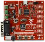
Figure 1-1 shows the Starter Kit board, along with the major hardware features.
FIGURE 1-1:
dsPIC33EV 5V CAN-LIN STARTER KIT FEATURES
9
8
10
11
12
7
6
13
14
5
4
DS50002311A-page 14
3
2
1
2014 Microchip Technology Inc.
�Introduction to the Starter Kit
1. dsPIC33EV256GM106 Digital Signal Controller (U1): this DSC is at the heart
of the application. It is responsible for managing communications for all three
serial protocols, using dedicated hardware peripherals for CAN and SENT, and
one of the DSC’s compatible UARTs for LIN. An external 8 MHz crystal (X1) provides stable timing. All of the I/O pins not used by the sensors and serial interfaces are available on the breakout connector.
2. User Push Buttons and LEDs: three push buttons (S1 through S3) are provided to simulate digital sensor data in the pre-programmed application. The
switches and their associated red LEDs (LED1 through LED3) are connected to
dedicated I/O port pins. The switches have external pull-ups, and thus read a
logic low when depressed. The LEDs are lit when their port pins are driven high.
The LEDs are low-current types, consuming approximately 2 mA each when lit.
3. Master Clear Push Button: pressing this button causes a Master Clear reset of
the DSC and the running application.
4. Potentiometer (R14): the linear trim potentiometer is used to simulate analog
sensor readings for the pre-programmed application. The wiper is connected to
the DSC’s A/D converter; the body is connected between ground and I/O port
RG8. Driving RG8 high makes the potentiometer a divider between VDD and
ground. Driving RG8 low disables the potentiometer, and allows for reduced
power consumption. R13 and C20 form a low-pass, anti-aliasing filter.
5. CAN Interface: this uses the Microchip MCP2561 CAN driver/receiver, which
can operate up to 1 MB/s. Connections to external CAN devices are made
through J2, a standard DB9 serial connector. An optional 120 bus termination
resistor is controlled via jumper J7.
6. LIN Interface: this uses the Microchip MCP2021A LIN controller (U10), and is
fully compliant with the LIN 2.x/SAE J2602-2 specifications. Screw terminal connections are provided for battery power in Master mode (J4) and data bus connections in Master and Slave modes (J8). Jumper J1 is used to select the
operating mode.
7. SENT Interface: screw terminals (J9) are provided for data connections. The
bus pull-up is controlled with jumper JP2.
8. ICSP Header (J10): space is provided for a standard 6-pin In-Circuit Serial Programming™ connector (FCI 68016-106HLF) for the dsPIC33EV256GM106
DSC. This allows for in-circuit emulation and debugging using Microchip’s
MPLAB REAL ICE™ in-circuit emulator, as well as direct programming of the
DSC.
9. Power LED (D5): this LED is lit when USB bus power is available to the USB
connector.
10. USB Port (J6): the mini-B port provides programming/debugging connectivity
and power to the Starter Kit. Bus power (+5 VDC) is provided to the DSC side of
the Starter Kit through a noise filter network (L1/C47).
Note:
The CAN-LIN Starter Kit can only be powered through the USB port. No
other provisions to supply power to the board are available.
11. PICkit 3 On Board (PKOB): the PIC24FJ256GB106 microcontroller provides a
simple programming interface between the dsPIC33EV256GM106 DSC and
MPLAB IDE software for programming and debugging. A 3.3V regulator (U8)
provides power to the circuit. Since the DSC operates at 5V, level translators (U2
and U3) are used for the internal serial clock programming signals. Space for a
legacy 6-pin PICkit programmer expansion header (J5) to program the PKOB
microcontroller is also provided.
2014 Microchip Technology Inc.
DS50002311A-page 15
�dsPIC33EV 5V CAN-LIN Starter Kit User’s Guide
12. Current Measurement Shunt (JP1): the operating current of the DSC can be
measured here by removing the jumper and placing an ammeter across the pins.
Running the demo at 40 MIPS results in current consumption of approximately
34 mA (from the +5VDC rail).
13. Temperature Sensor (U7): the MCP9701A analog temperature sensor measures the board’s temperature; its analog output is connected to AN18 of the
12-bit ADC. The sensor’s scale is 19.5 mV/°C nominal. The ADC uses VDD (5V)
as its reference, so each bit represents a 12.2 mV step. The circuit can resolve
±1°C.
14. Breakout Connector (J3): many of the DSC’s I/O pins are accessible through
this connector footprint. The user can solder in a male or female 2x25 pin header
(2.54mm pin spacing). Individual wires can be soldered into the connector holes.
Table 1-1 lists the expansion header’s connections to the DSC.
TABLE 1-1:
J3 Pin
Function
Device Pin
J3 Pin
Function
Device Pin
1
MCLR(1)
7
26
GND
—
2
GND
—
27
RB9
49
3
RE12
27
28
RC0
21
4
RG8(1)
6
29
RB10
60
5
RE13
28
30
RC1
22
6
RG9
8
31
RB11
61
7
RE14
29
32
RC2
23
8
GND
—
33
RB12
62
9
RE15
30
34
RC3
35
10
DVDD
10, 26, 38, 57
35
RB13
63
11
GND
—
36
RC4(1)
36
12
RA0
13
37
RB14
2
13
RB0
15
38
RC5(1)
37
14
RA1
14
39
RB15
3
15
RB1
16
40
RC6(1)
50
16
RA4
33
41
GND
—
17
RB2
17
42
RC7(1)
51
18
RA9
34
43
DVDD
10, 26, 38, 57
19
RB3
18
44
RC8(1)
52
20
RA10
64
45
RC11
24
21
RB4(2)
32
46
RC9(1)
55
22
RA11
12
47
RC13
47
23
RB7
46
48
RC10
45
24
RA12
11
49
GND
-
25
RB8
48
50
GND
-
Note 1:
2:
DS50002311A-page 16
EXPANSION CONNECTOR PINOUT
Shared I/O pin; refer to schematic for details.
RB4 is also used for the UART Log Data for the pre-programmed application.
2014 Microchip Technology Inc.
�Introduction to the Starter Kit
1.4
INSTALLING DEVICE DRIVERS FOR THE STARTER KIT
The proper USB drivers for the Starter Kit are included in the MPLAB X IDE installation
(Windows, iOS or Linux). The first time the Starter Kit is attached to the IDE, a notification window may appear that USB drivers are being installed.
2014 Microchip Technology Inc.
DS50002311A-page 17
�dsPIC33EV 5V CAN-LIN Starter Kit User’s Guide
NOTES:
DS50002311A-page 18
2014 Microchip Technology Inc.
�dsPIC33EV 5V
CAN-LIN STARTER KIT
USER’S GUIDE
Chapter 2. The Demonstration Application
The Starter Kit board is pre-programmed with a small application to demonstrate its
functionality in its three serial automotive interfaces (CAN, LIN and SENT). The application can either operate as a Transmitter (Master) or as a Receiver (Slave), but not
both at once.
The application’s mode is set at power-up, or when a Master Clear event occurs, as
follows:
• if none of the push buttons are depressed during power-up or while the MCLR
push button is pressed, the three LEDs will light in sequence 1-2-3, and turn off in
reverse sequence (3-2-1). The board is now in Transmit/Master mode.
• if any of the push buttons are depressed during power-up or while the MCLR push
button is pressed, all three LEDs will blink together five times, and then remain lit
until the push button(s) are released. This places the board in Receive/Slave
mode.
2.1
TRANSMIT/MASTER MODE
When the application is running in Transmit mode, it executes an endless one-second
loop as the main routine, which performs the following:
1. The state of the push buttons is read, and the corresponding LED is lit if the button is pressed.
2. The temperature sensor is sampled, and its analog output converted.
3. RG8 is driven high (+5V), and the voltage on the potentiometer is read.
4. The results of (1), (2) and (3) are formatted and transmitted on each of the three
serial interfaces, starting with the CAN interface.
5. The UART monitor sends a formatted ASCII text message from pin RB4 (see
Section 2.3 “UART Monitoring Log” for details).
6. The application waits until the timer tick ends, and then repeats the process.
While the LIN and SENT interfaces do not need to be connected in Transmit mode, an
external active CAN bus or CAN analyzer must be connected to the CAN port; this is
due to the CAN requirement of receiving an external ACK signal before transmitting a
message. Unless the CAN portion of the application is disabled, the application will
pause and wait indefinitely without an external connection, and no LIN or SENT data
will be transmitted. See Section 3.1 “Removing CAN from the Demo Application”
for information on reconfiguring the application.
2014 Microchip Technology Inc.
DS50002311A-page 19
�dsPIC33EV 5V CAN-LIN Starter Kit User’s Guide
2.1.1
SENT Data Transmission Formatting
The SENT message consists of the following:
•
•
•
•
A Synchronization/Calibration period (pulse) of 56 tick times
A Status nibble of 12 to 27 tick times. This is user defined
Up to six data nibbles of 12 to 27 tick times. The demo uses 6 nibbles (3 bytes)
A CRC nibble of 12 to 27 tick times
The tick time is set by a #define statement at 50 µs, with an allowable range of 3 µs
to 90 µs.
The SENT protocol uses nibbles, not bytes or words, to format the message. In the
demo application, the Status nibble encodes the state of the user-defined push buttons.
The data nibbles encode the potentiometer and temperature sensor readings. The Status and data nibbles are:
• Status: 0 S3 S2 S1, where S1 through S3 represents the status of the push buttons (a ‘1’ indicates that corresponding switch is pressed). The value of this nibble
reflects which button (if any) is pressed
• Nibbles 1 through 3: 12 bits of the ADC conversion value for the potentiometer
reading (MSbit to LSbit)
• Nibbles 4 through 6: 12 bits of the ADC conversion value for the temperature sensor (MSbit to LSbit)
The CRC is generated by the SENT module in hardware, and is not calculated by the
application.
Figure 2-1 shows a typical screen capture of SENT data transmitted by the application.
This data was captured using the KOPF Automotive Interface 4 analyzer and
KFlexExplorer software (KOPF GmbH).
FIGURE 2-1:
DS50002311A-page 20
SENT MESSAGES FROM THE STARTER KIT
2014 Microchip Technology Inc.
�The Demonstration Application
2.1.1.1
CONNECTING HARDWARE FOR SENT DATA TRANSMISSION
Connection to another SENT device is by two wires, SIGNAL and GROUND. The connections are made via J9.
The SENT bus requires a pull-up resistor, which is enabled by installing Jumper JP2. If
two Starter Kit boards are connected, enable the pull-up on only one of the boards;
remove the JP2 jumper on the other board. Similarly, if the Starter Kit is connected to
an existing SENT network which has a pull-up installed, remove the JP2 jumper.
Note:
2.1.2
The rise-time control filter on the Starter Kit is not guaranteed to meet the
requirements of the SENT standard in all possible applications. Refer to
SAE J2716 for filter design guidelines.
LIN Data Transmission Formatting
The various LIN timing parameters are set in the demo application in a series of
#define statements (Example 2-1). Connection to existing LIN networks or peripherals may require adjusting these parameters. The constant FCAN is the MIPS running
frequency in Hz.
EXAMPLE 2-1:
#define
#define
#define
#define
#define
#define
LIN TIMING PARAMETERS
FCAN
40000000
LIN_BAUD
4800
LIN_BIT_TIME ((1000000/LIN_BAUD) + 0.5)
LIN_BRGVAL ((FCAN/LIN_BAUD)/16) – 1
LIN_ID
0x23
LIN_BIT_STUFF
0x4
The data is transmitted as follows:
1. The ID byte, which includes two parity bits. The ID is set as a #define in the
demo program, and may be changed to any valid byte. The application uses
0x23 by default, which is transmitted with parity as 0xE2.
2. The second byte is the data for the three push button switches. S1 represents
the LSbit (bit 0), S2 is bit 1 and S3 is bit 2. A ‘1’ in a bit position shows the corresponding switch is depressed. Note that the switches are not debounced by the
application, and the switch states are sampled once every second; therefore,
there may be a delay to register a key press in the serial data.
3. The next two bytes are the raw temperature readings from the ADC. At room
temperature, expected data values are from 0x02D0 to 0x0320. The application
takes four readings and then averages them to send the final result.
4. The next two bytes are the potentiometer value from the ADC. The range is
approximately 0x000 to 0x0FFF (a small offset value is possible).
5. The final byte is the checksum, computed per LIN specification. Note that this is
an enhanced checksum calculation, which includes the ID byte in the calculation.
Figure 2-2 shows the LIN data output from the application, captured by using the Microchip LIN Serial Adapter (Microchip part # APGDT001) and associated software. This
shows the output of the LIN port running the demo software.
To set this in the LIN analyzer application, open the Setup menu and change the settings at the Setup dialog to:
• Baud Rate: 4800
• Timeout (ms): 1000
• COM Port: “APG USB to LIN 0”
2014 Microchip Technology Inc.
DS50002311A-page 21
�dsPIC33EV 5V CAN-LIN Starter Kit User’s Guide
FIGURE 2-2:
2.1.2.1
LIN MESSAGES FROM THE STARTER KIT
CONNECTING HARDWARE FOR LIN DATA TRANSMISSION
The LIN bus electrical signaling is controlled by a MCP2021A LIN transceiver (U10).
The standard LIN bus uses three wires: SIGNAL, GROUND and POWER (+12VDC).
The transceiver requires an external +12 VDC supply to be connected. The connections between the LIN bus (or other LIN device) and the Starter Kit are different for
Transmit and Receive modes. Table 2-1 summarized the differences.
In Transmit (Master) mode, the +12VDC is applied to the BAT terminal of J4, and the
battery ground is connected to the GND terminal. The LIN signal is applied to the SIG
terminal of J8. The SIG terminal is for the LIN signal wire, and the GND terminal is used
for the LIN ground. In addition, jumper J1 is set to position 1-2 for Transmit mode.
In Receive (Slave mode), J4 is not used. The +12 VDC is supplied over the bus
POWER wire, which is connected to the + terminal of J8. The SIG terminal is connected
to the LIN SIGNAL wire, and GND is for the GROUND wire. Jumper J1 is set to position
2-3 for Receive mode.
TABLE 2-1:
LIN CONNECTIONS FOR TRANSMIT AND RECEIVE MODES
Connector/Jumper
J1
J4
J8
DS50002311A-page 22
Master/Slave
Transmit
Receive
1-2 (Master)
2-3 (Slave)
BAT
POWER
—
GND
GROUND
—
+
—
POWER
SIG
SIGNAL
SIGNAL
GND
GROUND
GROUND
2014 Microchip Technology Inc.
�The Demonstration Application
2.1.3
CAN Data Transmission Formatting
CAN data is transmitted as follows:
1. The SID. The demo code arbitrarily uses 0x123, which is set by the #define
MSG_SID statement. It may be changed to any valid SID.
2. The DLC byte, which shows six bytes of data are to be transmitted.
3. The next two bytes (DATA 0 and DATA 1) are the data for the three switches. The
switch data appears on DATA 0, while DATA 1 is 0x00. S1 is the LSBit (bit 0), S2
is bit 1 and S3 is bit 2. A ‘1’ in a bit position shows the corresponding switch is
depressed. Note that the switches are not debounced by the application, and the
switch state are sampled once every second; therefore, there may be a delay to
register a key press in the serial data.
4. The following two bytes (DATA 2 and DATA 3) are the raw temperature readings
from the ADC. At room temperature, expected data values are from 0x02D0 to
0x0320. The application takes four readings and then averages them to send the
final result. DATA3 is the Most Significant Byte.
5. The final two bytes (DATA 4 and DATA 5) are the potentiometer value from the
ADC. The range is approximately 0x000 to 0x0FFF (a small offset value is possible). DATA 5 is the Most Significant Byte.
Figure 2-3 shows a typical CAN message from the demo application, as captured using
the Microchip CAN Bus Analyzer (Microchip part # APGDT002) and associated software running on Windows 7. This shows a potentiometer value reading of 0x057D, and
a raw temperature reading of 0x02E4. The CAN Analyzer shows that the CAN messages arrive 250 ms apart, as set by the application’s main timer loop.
The CAN Analyzer must be configured to the demo application’s parameters with the
Setup dialog (Setup > Hardware Setup). The correct setting are:
• Bitrate Control: 250 kbps
• Mode Control: Normal
• Termination Control: On
FIGURE 2-3:
2014 Microchip Technology Inc.
CAN MESSAGES FROM THE STARTER KIT
DS50002311A-page 23
�dsPIC33EV 5V CAN-LIN Starter Kit User’s Guide
2.1.3.1
CONNECTING HARDWARE FOR CAN DATA TRANSMISSION
The CAN bus should be double-terminated with 120 resistors at each end of the CAN
cable. Jumper J7 controls cable termination across the CAN data lines. When the
jumper is in the TERM position (positions 2-3), a 120 resistor is connected across the
cable.
When connecting two CAN-LIN Starter Kit boards to each other via a DB9
female-to-female serial cable, place the J7 jumpers in the TERM position on both
boards. Do not use more than two bus termination resistors.
The CAN connector (J2) follows the de facto industry standard for signal connection.
Table 2 lists the signal pins.
TABLE 2-2:
CAN CONNECTOR PINOUT (J2)
DB9 Pin
2.1.3.2
CAN Signal Name
1
NC
2
CAN_L
3
Ground
4
NC
5
NC
6
Ground
7
CAN_H
8
NC
9
NC
SPECIAL CONSIDERATIONS FOR CAN
For the demo application to properly execute, the CAN port must be connected to an
active CAN bus or CAN analyzer tool that provides an Acknowledge (ACK) signal to
the Starter Kit. If it is not connected, the demo application’s main loop will hang, waiting
for an ACK signal to be received; no LIN or SENT transmissions will be sent.
The application can be modified and re-compiled to disable CAN functionality and only
run the SENT and LIN portions. See Section 3.1 “Removing CAN from the Demo
Application” for details.
DS50002311A-page 24
2014 Microchip Technology Inc.
�The Demonstration Application
2.2
RECEIVE/SLAVE MODE
Receive/Slave mode is set by pressing and releasing the MCLR push button while
simultaneously pressing and holding any of the three push button switches. The three
LEDs rapidly flash in unison, then stay lit. Once they are all lit, release the held push
button.
While in Receive mode, the application waits for any of the three serial interfaces to
receive and process a valid message from another CAN-LIN Starter Kit running the
demo application in Transmit mode, or other external source. Once processed, the
LEDs will momentarily flash to indicate a valid received message, as follows:
• Valid CAN message: LED1
• Valid LIN message: LED2
• Valid SENT message: LED3
It is possible that messages sent by other sources will show a valid received message
if they are the correct baud/bit rates and have the same number of data bytes transmitted as the demo application.
Messages can be received from any or all of the connected ports at once, and multiple
messages will be validated.
2.3
UART MONITORING LOG
The demo application contains an independent message-logging UART in both Transmit and Receive mode. The UART uses ASCII-encoded serial data at 38,400 baud,
8-bit data, with 1 Start bit, 1 Stop bit and no parity (38400-8-1-1-N). The serial data is
sent to I/O pin RB4 on the Expansion Connector (J3). In Transmit mode, the logger
reports the current temperature (°C), the measured potentiometer voltage (V) and the
status of each push button switch. This data is then encoded and sent over each interface (in the order of SENT, LIN, then CAN).
Figure 2-4 displays a typical logging message in Transmit mode, as viewed on a terminal application. Note that this ASCII data is not what is physically sent over the interfaces. The data sent is raw data as described in the prior sections for each interface.
The data is described as local, as this is the data measured by the board about to
Transmit.
FIGURE 2-4:
2014 Microchip Technology Inc.
UART TRANSMIT LOG (TERMINAL DISPLAY)
DS50002311A-page 25
�dsPIC33EV 5V CAN-LIN Starter Kit User’s Guide
The UART logging code will decode the incoming messages if the board is in Receive
mode. CAN and LIN messages contain ID byte fields, and the logger will display these
as well. Figure 2-5 shows a typical decoded CAN message sent by another CAN-LIN
Starter Kit. The first line shows that a CAN message with an SID of 0x123 (the demo
application default SID) has been received.
FIGURE 2-5:
UART RECEIVE LOG (TERMINAL DISPLAY)
The application assumes that incoming messages in Receive mode are coming from
another CAN-LIN Starter Kit, and is thus hard-coded to parse and decode its own messages. Of course, it is possible to have non-demo messages received and parsed, but
the displayed data will be random; the only fields properly displayed will be the ID fields
for CAN and LIN. The source code can be edited and re-compiled to parse any message, or to simply display the raw data bytes like a typical analyzer.
The CAN portion only accepts SID messages. EID messages are not handled.
2.3.1
Connecting the Logger To A USB Host
The +5V UART serial data present on I/O pin RB4 must somehow get to a computer
terminal. The Microchip MCP2200 Breakout Module (Microchip part # ADM00393) provides one simple way to create a serial-to-USB interface. The module is available separately at the microchipDIRECT web site (www.microchipdirect.com).
The Breakout Module needs only three connections to the Starter Kit board via the
expansion riser (Table 2-3); none of the other ports on the Breakout Module are used.
The logger can then communicate to a host computer or terminal over USB. Driver support for the MCP2200 for both Windows and Linux is available.
TABLE 2-3:
Note:
DS50002311A-page 26
CONNECTIONS FOR THE BREAKOUT MODULE
Breakout Board Signal
Expansion Connector Signal
RX
RB4
VDD
DVDD
G
GND
The MCP2200 Breakout Module can operate on a VDD of either 3.3V or 5V,
which is selectable by a jumper. For this application, make sure that the
jumper is configured for 5V (positions 2-3).
2014 Microchip Technology Inc.
�dsPIC33EV 5V
CAN-LIN STARTER KIT
USER’S GUIDE
Chapter 3. Modifying the Application
The pre-programmed demo application for the Starter Kit can be easily modified to
change its operation, or removed and replaced with your own hardware-appropriate
application. To modify the application, develop new code, and/or program and debug
the dsPIC33EV256GM106 DSC, you will need the latest versions of MPLAB X IDE
(V2.10 or later) and MPLAB XC16 compiler (V1.23 or later). In addition, you will need
the Starter Kit demo application software, available as a zipped MPLAB X IDE project
file from the Microchip web site.
After unzipping the application archive and launching MPLAB X IDE, the Starter Kit
Demo project folder will appear in the Projects tab in the main view. The source code
for the demo application is a single C file, 33EV_main_v11.c. (no header files).
Before starting, verify that the project is configured correctly:
1. Right click on the folder, and select Properties.
2. In the Project Properties window, verify that the selected target device is the
dsPIC33EV256GM106.
3. If the Starter Kit is connected to the computer via the USB port, the serial number
associated with this Starter Kit’s PKOB should be displayed in the Hardware Tool
window, located in the Project Properties window. (Note that the serial number
will be unique for each PKOB.)
3.1
REMOVING CAN FROM THE DEMO APPLICATION
The pre-programmed Starter Kit application can be modified and re-compiled to omit
the CAN portion of the demo. To do this:
1. Open the source file (33EV_main_v11.c) in the MPLAB X IDE editor, or in a
suitable text editor.
2. Perform a text search to find the main function call for the CAN routine:
CAN_Transmit();
This code will be near line 472 of the source file.
3. Comment out that line.
4. Save and close the file.
5. Re-compile the source code, and load it into the DSC.
The demo application should now execute only the LIN and SENT portions. The overall
one-second loop timing of the application will remain the same.
2014 Microchip Technology Inc.
DS50002311A-page 27
�dsPIC33EV 5V CAN-LIN Starter Kit User’s Guide
NOTES:
DS50002311A-page 28
2014 Microchip Technology Inc.
�dsPIC33EV 5V
CAN-LIN STARTER KIT
USER’S GUIDE
Chapter 4. Troubleshooting
This chapter discusses common operational issues and how to resolve them.
1. The demo application does not run.
The Starter Kit board must be plugged into a powered USB hub, computer or other USB
Host device that supplies at least 80 mA. Start by plugging into the USB Device port,
J2. LED D5 should light when VBUS is detected.
If D5 is not lit, verify that the USB Host side port is functional.
Verify that Current Measurement Shunt JP1 is in place.
The default application requires that the Starter Kit be connected to an active CAN bus
or CAN analyzer. If it not connected, the demo will hang in its main loop and fail to run
at all. If a CAN bus or analyzer is not available, it will be necessary to disable the CAN
portion of the application. See Section 3.1 “Removing CAN from the Demo Application” for how to do this.
2. LIN (or SENT) data cannot be detected by the external bus analyzers.
Verify that the Signal and Ground wires (and Power for LIN) for the affected protocol
are connected to the Starter Kit correctly. Note that for the LIN protocol, different connections are used when the Starter Kit is in Transmit or Receive mode.
For LIN, verify that the position of jumper J1 is in the proper position for the Starter Kit’s
current mode.
For SENT, verify that jumper JP2 is installed, enabling the pull-up resistor.
3. The Starter Kit is correctly connected to an external CAN bus or CAN Analyzer, but the external device is having problems receiving CAN messages
from the Starter Kit.
Verify that the CAN bus is properly terminated. If there are only two devices connected
(e.g., the Starter Kit and an analyzer), verify that the CAN terminating resistor is
enabled (jumper J7 is installed), and that the other device is properly terminated. If
there are more than two devices, verify that two and only two are terminated.
Verify that the CAN baud rate is set at 250 kbps. When using the CAN analyzer software provided with the Microchip CAN Bus Analyzer, use the Setup dialog (Setup >
Hardware Setup) to check and/or change the setting. (For other CAN analyzer packages, refer to the instructions provided with the software.)
2014 Microchip Technology Inc.
DS50002311A-page 29
�dsPIC33EV 5V CAN-LIN Starter Kit User’s Guide
NOTES:
DS50002311A-page 30
2014 Microchip Technology Inc.
�dsPIC33EV 5V
CAN-LIN STARTER KIT
USER’S GUIDE
Appendix A. Starter Kit Schematics
The following schematic diagrams (Revision 2.0) are included in this appendix:
Application:
• Figure A-1: Application DSC and Associated Components
Programmer/Debugger:
• Figure A-2: PICkit On Board Programmer/Debugger
2014 Microchip Technology Inc.
DS50002311A-page 31
�dsPIC33EV 5V CAN-LIN Starter Kit User’s Guide
FIGURE A-1:
STARTER KIT, SHEET 1 (dsPIC33EV256GM106-SIDE COMPONENTS)
DVDD
DVDD
R36
C2
C3
C4
C5
0.1 µF
50V
0603
0.1 µF
50V
0603
0.1 µF
50V
0603
0.1 µF
50V
0603
Pin 10
Pin 26
Pin 38
Pin 57
1k 1%
0603
S4
1
R43
4
2
U1
100R 1%
TG_MCLR
0603
3
TACT SPST
7
56
VCAP
C1
10 µF
25V
1206
10
26
38
57
19
DVDD
DVDD
0.22 µF
50V
0805
RG8
3
R14
2
1
25K
3352E
R13
SENT_1
LIN_TX
LIN_RX
53
54
42
RE12
RE13
RE14
RE15
27
28
29
30
RA0
RA1
RA4
LIN_CS
LIN_TXE
RA9
RA10
RA11
RA12
15
16
17
18
32
43
44
46
48
49
60
61
62
63
2
3
21
22
23
35
36
37
50
51
52
55
45
24
39
47
40
OA3OUT/AN6/C3IN4-/C4IN4-/C4IN1+/RP48/RC0
OA3IN-/AN7/C3IN1-/C4IN1-/RP49/RC1
OA3IN+/AN8/C3IN3-/C3IN1+/RPI50/U1RTS/BCLK1/FLT3/RC2
AN12/C2IN2-/C5IN2-/U2RTS/BCLK2/FLT5/RE12
AN29/SCK1/RPI51/RC3
AN30/CVREF+/RPI52/RC4
AN13/C3IN2-/U2CTS/FLT6/RE13
AN14/RPI94/FLT7/RE14
AN31/RPI53/RC5
AN15/RPI95/FLT8/RE15
AN53/RP54/RC6
AN52/RP55/RC7
RPI96/RF0
AN51/RP56/RC8
RP97/RF1
AN54/RP57/RC9
AN48/CVREF2O/RPI58/RC10
AN19/RP118/RG6
AN11/C1IN2-/U1CTS/FLT4/RC11
AN18/RPI119/RG7
OSC1/CLKI/AN49/RPI60/RC12
AN17/RP120/RG8
RPI61/RC13
AN16/RPI121/RG9
OSC2/CLKO/RPI63/RC15
4
5
6
8
TEMP
RG8
RG9
13
14
33
1
31
34
64
12
11
PGED3/OA2IN-/AN2/C2IN1-/SS1/RPI32/CTED2/RB0
PGEC3/OA1OUT/AN3/C1IN4-/C4IN2-/RPI33/CTED1/RB1
PGEC1/ OA1IN+/AN4/C1IN3-/C1IN1+/C2IN3-/RPI34/RB2
PGED1/OA1IN-/AN5/C1IN1-/(CTMUC)/RP35/RB3
FLT32/RP36/RB4
PGED2/SDA1/RP37/RB5
PGEC2/SCL1/RP38/RB6
OA5OUT/AN25/C5IN4-/RP39/INT0/RB7
AN26/CVREF1O/ASCL1/RP40/T4CK/RB8
OA5IN-/AN27//C5IN1-/ASDA1/RP41/RB9
RP42/PWM1H3/RB10
RP43/PWM1L3/RB11
RPI44/PWM1H2/RB12
RPI45/PWM1L2/CTPLS/RB13
RPI46/PWM1H1/T3CK/RB14
RPI47/PWM1L1/T5CK/RB15
RP69/RD5
RP70/RD6
RPI72/RD8
58
59
CAN_RX
CAN_TX
100R 1%
0603
VDD
VDD
VDD
VDD
AVDD
9 VSS
25 VSS
41
20 VSS
AVSS
C12
dsPIC33EV256GM106 TQFP-64
OA2OUT/AN0/C2IN4-/C4IN3-/RPI16/RA0
OA2IN+/AN1/C2IN1+/RPI17/RA1
OA5IN+/AN24/C5IN3-/C5IN1+/SDO1/RP20/T1CK/RA4
AN55/RA7
RPI24/RA8
AN28/SDI1/RPI25/RA9
AN56/RA10
AN9/RPI27/RA11
AN10/RPI28/RA12
MCLR
DVDD
R17
DVDD
R12
R16
10k 1%
0603
10k 1%
0603
10k 1%
0603
S1
1
S1
1k 1%
0603
RB0
RB1
RB2
RB3
RB4
iCSP_DAT
iCSP_CLK
RB7
RB8
RB9
RB10
RB11
RB12
RB13
RB14
RB15
2
R25
1k 1%
0603
S2
2
R29
1k 1%
0603
4
3
S3
1
S3
4
3
1
S2
2
4
3
TACT SPST
RC0
RC1
RC2
RC3
LD1
LD2
LD3
S1
S2
S3
RC10
RC11
RC13
DVDD
R11
R2
LD1
1k 1%
0603
R3
LD2
1k 1%
0603
R4
LD3
X1
1k 1%
0603
LED1
RED
LED2
RED
LED3
RED
8MHz
C20
C13
C14
2200pF
50V
27pF
50V
27pF
50V
DVDD
VOUT
JP2
R32
1
2
1 VDD
DVDD
J9
2
1
2
3
4
5
6
TEMP
GND 3
282834-2
R35
1
SENT_1
47R 1%
J10
U7 MCP9701A
R15
2.2k 1%
C33
2
47R 1%
DNP
C31
TG_MCLR
RE12
RE13
RE14
RE15
J2
U6 MCP2561
J7
120R 1%
CAN1L
CAN1H
7
CAN1H
1
2
3
5
6
CAN1L
CANH
TXD
SPLIT
STBY
CANL
RXD
VDD
VSS
1
CAN_TX
8
RG9
4
CAN_RX
3
DVDD
2
C11
0.1 µF
50V
RB0
RB1
RB2
RB3
RB4
RB7
RB8
RB9
RB10
RB11
RB12
RB13
RB14
RB15
DVDD
RC11
RC13
DVDD
R40
49 47 4543 4139 3735333129 2725232119 17 151311 9 7 5 3 1
50 48 4644 424038 36 34323028 26 24222018 16 141210 8 6 4 2
J3
DE-9 Male
R9
RB0
RB1
0.1 µF
50V
2200pF
50V
1
6
2
7
3
8
4
9
5
TG_MCLR
DVDD
RG8
RG9
DVDD
RA0
RA1
RA4
RA9
RA10
RA11
RA12
RC0
RC1
RC2
RC3
LD1
LD2
LD3
S1
S2
S3
RC10
10k 1%
1 RXD FAULT/TXE
8
LIN_CS
2
7
CS/LWAKE
3 VREG
R45
LBUS
VSS
6
C18
0.1 µF
50V
5
MRA4003T3G
J4
C19
10 µF
50V
D2
43V
10 µF
50V
DNP
282834-2
JP1
VUSB
C16
DVDD
1 2
J8
J1
3 2 1
10k 1%
4 TXD
D1
LIN_TXE
R10
D3
1k 1%
BAS21
3 2 1
LIN_TX
VBB
R47
1k 1%
2 1
U10 MCP2021A
LIN_RX
282834-3
TP1
TP2
TP LOOP Black
TP LOOP Black
D4
27V
DS50002311A-page 32
2014 Microchip Technology Inc.
�Starter Kit Schematics
FIGURE A-2:
STARTER KIT, SHEET 2 (PICkit™ ON-BOARD PROGRAMMER)
Q3V3
C21
C22
C23
C25
C26
0.1 µF
50V
0.1 µF
50V
0.1 µF
50V
0.1 µF
50V
0.1 µF
50V
PK3V3
R23
1k 1%
PK3V3
Pin10
R8
Pin26
Pin38
Pin19
Pin19
10k 1%
J5
U4
1
2
3
4
5
6
PK3V3
PK3V3
R18
ICSP_PGED_PICKIT3
ICSP_PGEC_PICKIT3
C24
10 µF
25V
HDR-1.27 Female 1x6
DNP
L2
PK3V3
Q3V3
220 OHM
MCLR
ENVREG
56
34
35
VCAP/VDDCORE
VBUS
VUSB
10
26
38
19
VDD
VDD
VDD
AVDD
9
25
41
20
VSS
VSS
VSS
AVSS
PIC24FJ256GB106
1
2
3
4
5
D_VBUS
USB_D_N
USB_D_P
16
15
14
13
12
11
17
18
21
22
23
24
27
28
29
30
R22
OSCI/CLKI/CN23/RC12
SOSCI/C3IND/CN1/RC13
SOSCO/T1CK/C3INC/RPI37/CN0/RC14
OSCO/CLKO/CN22/RC15
39
47
48
40
ASSEMBLY_ID_0
ASSEMBLY_ID_1
VUSB
220 OHM
C47
0.22 µF
50V
0
58
59
33
31
32
USB MINI-B Female
USB INTERFACE
(BUS POWERED)
37
36
4
5
6
8
USB_D_P
USB_D_N
R24
PGED1/AN0/VREF+/RP0/PMA6/CN2/RB0
PGEC1/AN1/VREF-/RP1/CN3/RB1
AN2/C2INB/VMIO/RP13/CN4/RB2
AN3/C2INA/VPIO/CN5/RB3
PGED3/AN4/C1INB/USBOEN/RP28/CN6/RB4
PGEC3/AN5/C1INA/VBUSON/RP18/CN7/RB5
PGEC2/AN6/RP6/CN24/RB6
PGED2/AN7/RP7/RCV/CN25/RB7
AN8/RP8/CN26/RB8
AN9/RP9/PMA7/CN27/RB9
TMS/CVREF/AN10/PMA13/CN28/RB10
TDO/AN11/PMA12/CN29/RB11
TCK/AN12/PMA11/CTED2/CN30/RB12
TDI/AN13/PMA10/CTED1/CN31/RB13
AN14/CTPLS/RP14/PMA1/CN32/RB14
AN15/RP29/REFO/PMA0/CN12/RB15
L1
J6
VBUS
DD+
ID
GND
100k PK3V3
1%
7
57
VBUSST/VCMPST1/CN68/RF0
VCMPST2/CN69/RF1
RP16/USBID/CN71/RF3
SDA2/RP10/PMA9/CN17/RF4
SCL2/RP17/PMA8/CN18/RF5
ICSP_PGEC_PICKIT3
ICSP_PGED_PICKIT3
PK3V3
10k 1%
PK3V3
POWER_GOOD_PICKIT3
R21
10k 1%
Y3
UTIL_SDO
R20
12MHz
C27
SCK
SDI
SDO
UTIL_CS
27pF 50V
1k 1%
C28
27pF 50V
UTIL_WP
UTIL_SCK
UTIL_SDI
60
61
62
63
64
1
2
3
PMD0/CN58/RE0
PMD1/CN59/RE1
PMD2/CN60/RE2
PMD3/CN61/RE3
PMD4/CN62/RE4
PMD5/CN63/RE5
SCL3/PMD6/CN64/RE6
SDA3/PMD7/CN65/RE7
D+/RG2
D-/RG3
C1IND/RP21/PMA5/CN8/RG6
C1INC/RP26/PMA4/CN9/RG7
C2IND/RP19/PMA3/CN10/RG8
RP27/PMA2/C2INC/CN11/RG9
VDD_SENSE
VPP_SENSE
46
49
50
51
52
53
54
55
42
43
44
45
DMH/RP11/INT0/CN49/RD0
VCPCON/RP24/CN50/RD1
DPH/RP23/CN51/RD2
RP22/PMBE/CN52/RD3
RP25/PMWR/CN13/RD4
RP20/PMRD/CN14/RD5
C3INB/CN15/RD6
C3INA/CN16/RD7
RTCC/DMLN/RP2/CN53/RD8
DPLN/SDA1/RP4/CN54/RD9
SCL1/RP3/PMCS2/CN55/RD10
RP12/PMCS1/CN56/RD11
3.16k 1%
VREF_2.5V
CLK_EN
DATA_EN
R37
PK3V3
100k 1%
VPP_GND
R19
10k 1%
PK3V3
R27
10k 1%
U5 25LC256
UTIL_CS
UTIL_SCK
UTIL_SDO
UTIL_WP
R26
PK3V3
1
6
5
3
CS
SCK
SI
WP
VCC 8
7
HOLD
VSS 4
SO
PK3V3
2
PK3V3
UTIL_SDI
SDO
R28
PGED_L
330R 1%
C29
0.1 µF
50V
SDI
2.2k 1%
R30
330R 1%
SCK
DVDD
R38
3.92k 1%
R31
PGEC_L
330R 1%
R39
10k 1%
DVDD
PK3V3
VDD_SENSE
R41
2.21k 1%
R42
10R 1%
0603
1
R44
2.21k 1%
R1
U2 74LVC1T45GW
TG_MCLR
VPP_SENSE
100R 1%
6
VCCA VCCB
GND 2
5 DIR
3
4
A
B
DATA_EN
PGED_L
iCSP_DAT
C7
VPP_GND
R46
10k 1%
C
B
C8
0.1 µF
50V
0.1 µF
50V
R6
4.7k 1%
Q8
MMBT3904
E
DVDD
PK3V3
R5
10R 1%
U3 74LVC1T45GW
1
6
VCCA VCCB 2
GND
5 DIR
3A
4
B
CLK_EN
PGEC_L
iCSP_CLK
C9
C10
0.1 µF
50V
0.1 µF
50V
R7
4.7k 1%
U8 MCP1703/3.3V
1
VUSB
C30
VOUT
GND
2
3
PK3V3
C48
2.2 µF
25V
R33
R34
1k 1%
10k 1%
C46
0.1 µF
50V
1
1 µF
50V
VIN
POWER_GOOD_PICKIT3
D5
2
GREEN
2014 Microchip Technology Inc.
DS50002311A-page 33
�dsPIC33EV 5V CAN-LIN Starter Kit User’s Guide
NOTES:
DS50002311A-page 34
2014 Microchip Technology Inc.
�dsPIC33EV 5V
CAN-LIN STARTER
KIT USER’S GUIDE
Index
C
S
CAN
Data Transmission Formatting ......................... 23
Hardware Interface .......................................... 24
Removing from the Demo Application ............. 28
Special Considerations .................................... 24
Current Measurement Shunt .................................. 16
Customer Notification Service ................................. 10
Customer Support ................................................... 11
Schematic Diagrams .........................................31–33
SENT
Data Transmission Formatting ......................... 20
Hardware Interface .......................................... 21
D
Demonstration Application ...................................... 19
Device Driver .......................................................... 17
Documentation
Conventions ....................................................... 8
Layout ................................................................ 7
dsPIC33EV256GM106 DSC ................................... 15
E
Expansion Breakout Connector .............................. 16
H
Hardware Connections
CAN ................................................................. 24
LIN ................................................................... 22
SENT ............................................................... 21
T
Temperature Sensor ............................................... 16
Transmit/Master Mode ............................................ 19
CAN Data ......................................................... 23
LIN Data ........................................................... 21
SENT ............................................................... 20
Troubleshooting ...................................................... 29
U
UART Monitoring Log ............................................. 25
Connecting to a USB Host ............................... 26
USB Port ................................................................. 15
User Push Buttons and LEDs ................................. 15
W
Warranty Registration ............................................... 9
WWW Address ........................................................ 10
I
ICSP Header ........................................................... 15
Internet Address ..................................................... 10
L
LIN
Data Transmission Formatting ......................... 21
Hardware Interface .......................................... 22
M
MCLR Push Button ................................................. 15
Microchip Internet Web Site .................................... 10
Modifying the Application ........................................ 27
P
PICkit On Board (PKOB) ........................................ 15
Potentiometer ......................................................... 15
R
Reading, Recommended .......................................... 9
Removing CAN from the Application ...................... 28
2014 Microchip Technology Inc.
DS50002311A-page 35
�Worldwide Sales and Service
AMERICAS
ASIA/PACIFIC
ASIA/PACIFIC
EUROPE
Corporate Office
2355 West Chandler Blvd.
Chandler, AZ 85224-6199
Tel: 480-792-7200
Fax: 480-792-7277
Technical Support:
http://www.microchip.com/
support
Web Address:
www.microchip.com
Asia Pacific Office
Suites 3707-14, 37th Floor
Tower 6, The Gateway
Harbour City, Kowloon
Hong Kong
Tel: 852-2401-1200
Fax: 852-2401-3431
India - Bangalore
Tel: 91-80-3090-4444
Fax: 91-80-3090-4123
Austria - Wels
Tel: 43-7242-2244-39
Fax: 43-7242-2244-393
Denmark - Copenhagen
Tel: 45-4450-2828
Fax: 45-4485-2829
Atlanta
Duluth, GA
Tel: 678-957-9614
Fax: 678-957-1455
Austin, TX
Tel: 512-257-3370
Boston
Westborough, MA
Tel: 774-760-0087
Fax: 774-760-0088
Chicago
Itasca, IL
Tel: 630-285-0071
Fax: 630-285-0075
Cleveland
Independence, OH
Tel: 216-447-0464
Fax: 216-447-0643
Dallas
Addison, TX
Tel: 972-818-7423
Fax: 972-818-2924
Detroit
Novi, MI
Tel: 248-848-4000
Houston, TX
Tel: 281-894-5983
Indianapolis
Noblesville, IN
Tel: 317-773-8323
Fax: 317-773-5453
Los Angeles
Mission Viejo, CA
Tel: 949-462-9523
Fax: 949-462-9608
New York, NY
Tel: 631-435-6000
San Jose, CA
Tel: 408-735-9110
Canada - Toronto
Tel: 905-673-0699
Fax: 905-673-6509
DS50002311A-page 36
Australia - Sydney
Tel: 61-2-9868-6733
Fax: 61-2-9868-6755
China - Beijing
Tel: 86-10-8569-7000
Fax: 86-10-8528-2104
China - Chengdu
Tel: 86-28-8665-5511
Fax: 86-28-8665-7889
China - Chongqing
Tel: 86-23-8980-9588
Fax: 86-23-8980-9500
China - Hangzhou
Tel: 86-571-8792-8115
Fax: 86-571-8792-8116
China - Hong Kong SAR
Tel: 852-2943-5100
Fax: 852-2401-3431
China - Nanjing
Tel: 86-25-8473-2460
Fax: 86-25-8473-2470
China - Qingdao
Tel: 86-532-8502-7355
Fax: 86-532-8502-7205
China - Shanghai
Tel: 86-21-5407-5533
Fax: 86-21-5407-5066
China - Shenyang
Tel: 86-24-2334-2829
Fax: 86-24-2334-2393
China - Shenzhen
Tel: 86-755-8864-2200
Fax: 86-755-8203-1760
China - Wuhan
Tel: 86-27-5980-5300
Fax: 86-27-5980-5118
China - Xian
Tel: 86-29-8833-7252
Fax: 86-29-8833-7256
India - New Delhi
Tel: 91-11-4160-8631
Fax: 91-11-4160-8632
India - Pune
Tel: 91-20-3019-1500
Japan - Osaka
Tel: 81-6-6152-7160
Fax: 81-6-6152-9310
Japan - Tokyo
Tel: 81-3-6880- 3770
Fax: 81-3-6880-3771
Korea - Daegu
Tel: 82-53-744-4301
Fax: 82-53-744-4302
Korea - Seoul
Tel: 82-2-554-7200
Fax: 82-2-558-5932 or
82-2-558-5934
France - Paris
Tel: 33-1-69-53-63-20
Fax: 33-1-69-30-90-79
Germany - Dusseldorf
Tel: 49-2129-3766400
Germany - Munich
Tel: 49-89-627-144-0
Fax: 49-89-627-144-44
Germany - Pforzheim
Tel: 49-7231-424750
Italy - Milan
Tel: 39-0331-742611
Fax: 39-0331-466781
Italy - Venice
Tel: 39-049-7625286
Malaysia - Kuala Lumpur
Tel: 60-3-6201-9857
Fax: 60-3-6201-9859
Netherlands - Drunen
Tel: 31-416-690399
Fax: 31-416-690340
Malaysia - Penang
Tel: 60-4-227-8870
Fax: 60-4-227-4068
Poland - Warsaw
Tel: 48-22-3325737
Philippines - Manila
Tel: 63-2-634-9065
Fax: 63-2-634-9069
Singapore
Tel: 65-6334-8870
Fax: 65-6334-8850
Taiwan - Hsin Chu
Tel: 886-3-5778-366
Fax: 886-3-5770-955
Spain - Madrid
Tel: 34-91-708-08-90
Fax: 34-91-708-08-91
Sweden - Stockholm
Tel: 46-8-5090-4654
UK - Wokingham
Tel: 44-118-921-5800
Fax: 44-118-921-5820
Taiwan - Kaohsiung
Tel: 886-7-213-7830
Taiwan - Taipei
Tel: 886-2-2508-8600
Fax: 886-2-2508-0102
Thailand - Bangkok
Tel: 66-2-694-1351
Fax: 66-2-694-1350
China - Xiamen
Tel: 86-592-2388138
Fax: 86-592-2388130
China - Zhuhai
Tel: 86-756-3210040
Fax: 86-756-3210049
03/13/14
2014 Microchip Technology Inc.
�


 工商网监
湘ICP备2023018690号
工商网监
湘ICP备2023018690号
