KSZ8081RNB / KSZ8091RNB
10Base-T/100Base-TX
Physical Layer Transceiver
Evaluation Board User’s Guide
Revision 1.0 / August 2012
© Micrel, Inc. 2012
All rights reserved
Micrel is a registered trademark of Micrel and its subsidiaries in the
United States and certain other countries. All other trademarks are the
property of their respective owners.
The information furnished by Micrel in this datasheet is believed to be accurate and reliable. However, no responsibility is
assumed by Micrel for its use. Micrel reserves the right to change circuitry and specifications at any time without
notification to the customer. Micrel Products are not designed or authorized for use as components in life support
appliances, devices or systems where malfunction of a product can reasonably be expected to result in personal injury.
Life support devices or systems are devices or systems that (a) are intended for surgical implant into the body or (b)
support or sustain life, and whose failure to perform can be reasonably expected to result in a significant injury to the user.
A Purchaser's use or sale of Micrel Products for use in life support appliances, devices or systems is at Purchaser's own
risk and Purchaser agrees to fully indemnify Micrel for any damages resulting from such use or sale.
Micrel, Inc. 2180 Fortune Drive San Jose, CA 95131 U.S.A.
408-944-0800 (voice) 408-474-1000 (fax)
http://www.Micrel.com
�KSZ8081RNB / KSZ8091RNB 10Base-T/100Base-TX Evaluation Board User’s Guide
Revision History
Revision
1.0
Date
8/15/12
Summary of Changes
Initial Release
Micrel, Inc.
August 15, 2012
Rev. 1.0
2/13
�KSZ8081RNB / KSZ8091RNB 10Base-T/100Base-TX Evaluation Board User’s Guide
Table of Contents
1.0
2.0
3.0
4.0
Introduction ............................................................................. 5
Board Features ........................................................................ 5
Evaluation Kit Contents .......................................................... 5
Hardware Description ............................................................. 6
4.1
4.2
4.3
4.4
4.5
5.0
RMII (Reduced Media Independent Interface) ...................................................... 7
Jumper Setting & Definition .................................................................................. 9
Test Point Definition ............................................................................................. 12
RJ-45 Connector ................................................................................................... 12
LED Indicators ...................................................................................................... 12
Bill of Materials ...................................................................... 13
Micrel, Inc.
August 15, 2012
Rev. 1.0
3/13
�KSZ8081RNB / KSZ8091RNB 10Base-T/100Base-TX Evaluation Board User’s Guide
List of Figures
Figure 1. KSZ8081RNB Evaluation Board ..................................................................................... 6
Figure 2. KSZ8081RNB-EVAL interfacing with KSZ8463RLI Evaluation Board ............................ 7
List of Tables
Table 1.
Table 2.
Table 3.
Table 4.
Table 5.
Table 6.
Table 7.
Connector J2 - RMII Pin Definition ................................................................................... 8
KSZ8081RNB-EVAL / KSZ8091RNB-EVAL Strapping Jumper Definition....................... 9
KSZ8081RNB-EVAL / KSZ8091RNB-EVAL Loopback Jumper Definition ...................... 9
KSZ8081RNB-EVAL / KSZ8091RNB-EVAL Miscellaneous Jumper Definition ............. 10
Strapping Pin Definitions for KSZ8081RNB-EVAL / KSZ8091RNB-EVAL Jumpers...... 11
KSZ8081RNB-EVAL / KSZ8091RNB-EVAL Test Point Definition ................................. 12
KSZ8081RNB / KSZ8091RNB LED Definition ............................................................... 12
Micrel, Inc.
August 15, 2012
Rev. 1.0
4/13
�KSZ8081RNB / KSZ8091RNB 10Base-T/100Base-TX Evaluation Board User’s Guide
1.0
Introduction
The KSZ8081RNB / KSZ8091RNB is a 10Base-T/100Base-TX Physical Layer Transceiver with
an RMII MAC interface. It utilizes a unique mixed-signal design to extend signaling distance while
reducing power consumption, and offers HP Auto MDI/MDI-X for reliable detection of and
correction for crossover and straight-through cables, eliminating the need to differentiate between
crossover and straight-through cables. The KSZ8091RNB supports Energy Efficient Ethernet
(EEE) and Wake-On-LAN (WOL), while the KSZ8081RNB does not.
The KSZ8081RNB / KSZ8091RNB comes in a 32-pin, lead-free QFN package and provides an
ideal solution for 10Base-T/100Base-TX applications that have tight PCB board space.
The KSZ8081RNB and KSZ8091RNB Eval Boards (KSZ8081RNB-EVAL and KSZ8091RNBEVAL) provide a convenient platform to evaluate the features of the device. All configuration pins
are accessible either by jumpers, test points or interface connectors.
2.0
3.0
Board Features
Micrel KSZ8081RNB or KSZ8091RNB 10Base-T/100Base-TX Physical Layer
Transceiver
RJ-45 Jack for Fast Ethernet cable interface
HP Auto MDI/MDI-X for automatic detection and correction for straight-through and
crossover cables
RMII (Reduced Media Independent Interface) using an MII connector to interface with a
MAC controller
2 LED Indicators for status and activity
Jumpers to configure strapping pins
Manual Reset Button for quick reboot after re-configuration of strapping pins
Evaluation Kit Contents
The KSZ8081RNB and KSZ8091RNB Evaluation Kits include the following hardware:
KSZ8081RNB or KSZ8091RNB Evaluation Board
A design package with the following collaterals that can be downloaded from Micrel’s website at
http://www.micrel.com
KSZ8081RNB / KSZ8091RNB Eval Board Schematic (PDF and OrCAD DSN file)
KSZ80x1 (32-QFN) Eval Board Gerber Files (PDF version included)
KSZ8081RNB / KSZ8091RNB Eval Board User’s Guide (this document)
KSZ8081RNB and KSZ8091RNB IBIS Models
and the KSZ8081MNX / KSZ8081RNB and KSZ8091MNX / KSZ8091RNB Datasheets which are
also available from Micrel’s website.
Micrel, Inc.
August 15, 2012
Rev. 1.0
5/13
�KSZ8081RNB / KSZ8091RNB 10Base-T/100Base-TX Evaluation Board User’s Guide
4.0
Hardware Description
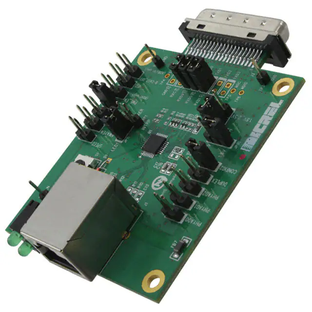
The KSZ8081RNB-EVAL / KSZ8091RNB-EVAL (shown in Figure 1) come in a compact form
factor and plugs directly into other boards with Ethernet MACs that expose the RMII interface
through an MII connector. Configuration of the KSZ8081RNB / KSZ8091RNB is accomplished
through on-board jumper selections and/or by PHY register access via the MDC/MDIO
management pins at the MII connector.
Figure 1. KSZ8081RNB Evaluation Board
Other features include an RJ-45 Jack for Fast Ethernet cable connection, programmable LED
indicators for reporting link status and activity, and a manual reset button for quick reboot after reconfiguration of strapping pins.
The KSZ8081RNB-EVAL / KSZ8091RNB-EVAL receives +5V DC input power through its MII
connector.
Micrel, Inc.
August 15, 2012
Rev. 1.0
6/13
�KSZ8081RNB / KSZ8091RNB 10Base-T/100Base-TX Evaluation Board User’s Guide
4.1
RMII (Reduced Media Independent Interface)
The KSZ8081RNB-EVAL / KSZ8091RNB-EVAL receives power and accesses RMII data and
management information from the MII connector J2. Figure 2 shows the KSZ8081RNB-EVAL /
KSZ8091RNB-EVAL connected to the Micrel KSZ8463RLI Evaluation Board.
Figure 2. KSZ8081RNB-EVAL interfacing with KSZ8463RLI Evaluation Board
Two RMII clocking modes are available with the KSZ8081RNB / KSZ8091RNB. It may utilize the
on-board 25 MHz crystal, connected to XI / XO, and output a 50 MHz REF_CLK signal which is
an input to the MAC device to which it is connected. REF_CLK drives pin 9 of the MII connector
J2. This is referred to as 25MHz Mode.
Alternatively, the device may be operated in 50MHz mode. In this mode, the KSZ8081RNB /
KSZ8091RNB receive the 50 MHz Reference Clock as an input on the XI pin, from pin 12 of the
MII connector J2. This clock may be sourced either from the MAC device, or from a separate
clock source on the MAC board. The following board changes are required to support 50MHz
mode:
1. Remove crystal circuit (Y1, C16, C17) and TXC clock termination (R6).
2. Populate R14 with 0 Ohm and R19 with 33 Ohm to connect RMII 50 MHz reference clock
(from J2 pin 12) to U1 pin 9 (XI input).
Additionally, register 1Fh bit [7] must be set to ‘1’ to select 50MHz mode.
Micrel, Inc.
August 15, 2012
Rev. 1.0
7/13
�KSZ8081RNB / KSZ8091RNB 10Base-T/100Base-TX Evaluation Board User’s Guide
The MII Management Interface (MIIM) is conducted thru pins MDC (clock line) and MDIO (data
line) on the MII connector J2. MIIM allows upper-layer devices to monitor and control the states of
the KSZ8081RNB / KSZ8091RNB. An external device with MDC/MDIO capability can be used to
read the PHY status or configure the PHY registers. The MIIM frame format and timing
information can be found in the KSZ8081RNB and KSZ8091RNB datasheets and in Clause 22 of
the IEEE 802.3 Specification.
The Eval Board has a 40-pin male edge connector that interfaces with and plugs directly into a
Fast Ethernet MAC board with the mating AMP 787170-4 (40-pin, right angle, female) connector.
Table 1 lists the pin outs for the RMII interface on connector J2.
Pin #
Signal
Pin #
Signal
1
+5V
21
+5V
2
MDIO
22
Ground
3
MDC
23
Ground
4
24
Ground
5
25
Ground
6
RXD[1]
26
Ground
7
RXD[0]
27
Ground
8
CRSDV
28
Ground
9
29
Ground
10
RXER
30
Ground
11
31
Ground
12
TXCLK
32
Ground
13
TXEN
33
Ground
14
TXD0
34
Ground
15
TXD1
35
Ground
16
36
Ground
17
37
Ground
18
38
Ground
19
39
Ground
20
+5V
40
+5V
Table 1. Connector J2 - RMII Pin Definition
Micrel, Inc.
August 15, 2012
Rev. 1.0
8/13
�KSZ8081RNB / KSZ8091RNB 10Base-T/100Base-TX Evaluation Board User’s Guide
4.2
Jumper Setting & Definition
At power-up, the KSZ8081RNB / KSZ8091RNB are configured using the chip’s internal pull-up
and pull-down resistors with its default strapping pin values. Jumpers are provided to override the
default settings, allowing for quick configuration and re-configuration of the board. To override the
default settings, simply select and close the desired jumper setting(s) and toggle the on-board
manual reset button (S1) for the new setting(s) to take effect. The KSZ8081RNB-EVAL /
KSZ8091RNB-EVAL strapping jumper settings are defined in Table 2 below.
Jumper
Definition
Open (default)
Close
J3
PHYAD0
1
0
J4
PHYAD1
0
1
J5
PHYAD2
0
1
J6
CONFIG0
J7
CONFIG1
CONFIG[2:0]
Mode
J8
CONFIG2
[open, open, close]
RMII
[close, open, close]
RMII Back-to-Back
All other CONFIG[2:0] settings not listed are
reserved (not used).
J9
Isolate Mode
Disable
Enable
J10
Nway Auto-Negotiation
Enable
Disable
J11
Forced Speed (KSZ8081 only)
100Base-TX
10Base-T
J12
Forced Duplex
Half
Full
J25
Broadcast Off – for PHY Address 0
Broadcast PHY address
Unique PHY address
J26
PME_N Pin Enable (KSZ8091 only)
Disable
Enable
Table 2. KSZ8081RNB-EVAL / KSZ8091RNB-EVAL Strapping Jumper Definition
The KSZ8081RNB-EVAL / KSZ8091RNB-EVAL has another set of jumpers that may be used to
loopback the RMII interface. To loopback, four jumpers must be installed. The individual jumpers
are defined in Table 3.
Jumper
RMII Signals
Normal Operation
RMII Loopback Mode
J13
RXDV / TXEN
Open
J14
RXC / TXC
Open
Close
Close
J16
Not used
J17
RXD1 / TXD1
Open
Close
J18
RXD0 / TXD0
Open
Close
J19
Not used
Table 3. KSZ8081RNB-EVAL / KSZ8091RNB-EVAL Loopback Jumper Definition
Micrel, Inc.
August 15, 2012
Rev. 1.0
9/13
�KSZ8081RNB / KSZ8091RNB 10Base-T/100Base-TX Evaluation Board User’s Guide
The last group of jumpers is defined in Table 4 below. These jumpers are not related to reset
strapping, nor to loopback. Two jumpers are used to set the VDDIO voltage, and one jumper is
used to route pin 31 as dependent on the device part number.
Note that for the eval board to function, a jumper must be installed on JP3. If pins 1 & 2 of JP3
are closed, then a jumper must also be installed on JP10.
For the KSZ8091RNB, a jumper must be installed on pins 2 & 3 of JP11.
Jumper
Definition
Close pins 1, 2
Close pins 2, 3
JP3
VDDIO voltage selection: 3.3V / low
VDDIO set by JP10
VDDIO = 3.3V
JP10
VDDIO low voltage selection
1.8V_2.5V = 1.8V
1.8V_2.5V = 2.5V
JP11
Pin 31 connection (LED1 or TXER)
For KSZ8081 only
(pin 31 = LED1)
For KSZ8091 only
(pin 31 = TXER)
Table 4. KSZ8081RNB-EVAL / KSZ8091RNB-EVAL Miscellaneous Jumper Definition
Table 5 lists the strapping pin definitions for the KSZ8081RNB-EVAL / KSZ8091RNB-EVAL
jumpers.
Jumper
Pin
Pin Name
Pin Function
J5
J4
J3
15
14
13
PHYAD2
PHYAD1
PHYAD0
The PHY Address is latched at power-up / reset and is
configurable to any value from 0 to 7.
The default PHY Address is 00001.
PHY Address 00000 is enabled only if the B-CAST_OFF
strapping pin is pulled high.
PHY Address bits [4:3] are always set to ‘00’.
J8
J7
J6
18
29
28
CONFIG2
CONFIG1
CONFIG0
The CONFIG[2:0] strap-in pins are latched at power-up /
reset and are defined as follows:
CONFIG[2:0]
Mode
001
RMII
101
RMII Back-to-Back
All other CONFIG[2:0] settings not listed are reserved (not
used).
J9
20
ISO
ISOLATE mode
Pull-up = Enable
Pull-down (default) = Disable
At the de-assertion of reset, this pin value is latched into
register 0h bit 10.
Micrel, Inc.
August 15, 2012
Rev. 1.0
10/13
�KSZ8081RNB / KSZ8091RNB 10Base-T/100Base-TX Evaluation Board User’s Guide
Jumper
Pin
Pin Name
Pin Function
J11
31
SPEED
(KSZ8081 only)
SPEED mode
Pull-up (default) = 100Mbps
Pull-down = 10Mbps
At the de-assertion of reset, this pin value is latched into
register 0h bit 13 as the Speed Select, and also is latched
into register 4h (Auto-Negotiation Advertisement) as the
Speed capability support.
J12
16
DUPLEX
DUPLEX mode
Pull-up (default) = Half Duplex
Pull-down = Full Duplex
At the de-assertion of reset, this pin value is latched into
register 0h bit 8 as the Duplex Mode.
J10
30
NWAYEN
Nway Auto-Negotiation Enable
Pull-up (default) = Enable Auto-Negotiation
Pull-down = Disable Auto-Negotiation
At the de-assertion of reset, this pin value is latched into
register 0h bit 12.
J25
19
B-CAST_OFF
Broadcast Off – for PHY Address 0
Pull-up = PHY Address 0 is set as a unique PHY
address
Pull-down (default) = PHY Address 0 is set as a
broadcast PHY address
At the de-assertion of reset, this pin value is latched by the
chip.
J26
22
PME_EN
(KSZ8091 only)
PME_N Output Pin for Wake-On-LAN Function
Pull-up = Enable
Pull-down = Disable
At the de-assertion of reset, this pin value is latched into the
chip.
N/A
21
NAND_Tree#
NAND Tree Mode
Pull-up (default) = Disable
Pull-down = Enable
At the de-assertion of reset, this pin value is latched by the
chip.
Table 5. Strapping Pin Definitions for KSZ8081RNB-EVAL / KSZ8091RNB-EVAL Jumpers
Micrel, Inc.
August 15, 2012
Rev. 1.0
11/13
�KSZ8081RNB / KSZ8091RNB 10Base-T/100Base-TX Evaluation Board User’s Guide
4.3
Test Point Definition
The KSZ8081RNB-EVAL / KSZ8091RNB-EVAL has four test points. They are defined in the
following table.
Test Point
Definition
TP1
Pin 21 (with external pull-up)
KSZ8081: Interrupt
KSZ8091: Interrupt or PME_N2
TP2
Ground
TP3
Ground
TP7
Pin 30
KSZ8081: LED0
KSZ8091: LED0 or PME_N1
Table 6. KSZ8081RNB-EVAL / KSZ8091RNB-EVAL Test Point Definition
4.4
RJ-45 Connector
The RJ-45 Connector (J1) is a TDK TLA-6T718A or similar integrated magnetic jack. It connects
to standard CAT-5 Ethernet cable to interface with 10Base-T / 100Base-TX Ethernet devices.
4.5
LED Indicators
A dual LED indicator (LED1) is located adjacent to the RJ-45 Connector. The top LED and bottom
LED are connected to LED1 (pin 31) and LED0 (pin 30) respectively.
The two LEDs are programmable to LED mode ‘00’ or ‘01’ via register 1Fh bits [5:4], and are
defined in the following table.
LED Mode
LED1 (pin 31)
LED0 (pin 30)
00
Speed
Pin
State
LED
Definition
Link/
Activity
Pin
State
LED
Definition
10Base-T
H
OFF
No Link
H
OFF
100Base-Tx
L
ON
Link
L
ON
Activity
Toggle
Blinking
01
Activity
Pin
State
LED
Definition
Link
Pin
State
Definition
No Activity
H
OFF
No Link
H
OFF
Activity
Toggle
Blinking
Link
L
ON
10
Reserved – not used
Reserved – not used
11
Reserved – not used
Reserved – not used
Table 7. KSZ8081RNB / KSZ8091RNB LED Definition
Micrel, Inc.
August 15, 2012
Rev. 1.0
12/13
�KSZ8081RNB / KSZ8091RNB 10Base-T/100Base-TX Evaluation Board User’s Guide
5.0
Bill of Materials
KSZ8081RNB / KSZ8091RNB Eval Board, Schematic Revision 1.0
Item
Quantity
Reference
Description
Package
1
2
C1,C2
47uF / Tantalum
B-size
2
1
C3
22uF / Tantalum
B-size
3
10
C4,C5,C7,C10,C11,C12,
0.1uF
0603
C49,C51,C57,C58
4
4
C6,C8,C48,C50
10uF / Tantalum
A-size
5
1
C9
2.2uF
A-size
6
2
C16,C17
22pF
0603
7
1
C52
470pF
0603
8
1
D1
1N4148
DO-35 / axial lead
9
2
FB1,FB7
Ferrite Bead
1206
10
1
J1
RJ-45 Mag Jack
thru hole / PC mount
11
1
J2
Male MII Connector
PCB edge mount
12
18
J3,J4,J5,J6,J7,J8,J9,J10,
Header 2X1
thru hole / 0.1" pitch
J11,J12,J13,J14,J16
J17,J18,J19,J25,J26
13
3
JP3,JP10,JP11
Header 3X1
thru hole / 0.1" pitch
14
1
LED1
LEDx2 / Green
thru hole / 0.1" pitch
15
1
R1
100K
0603
16
1
R2
10K
0603
17
9
R3,R25,R26,R27,R28,
4.7K
0603
33
0603
R29,R30,R102,R103
18
10
R4,R5,R6,R7,R8,R9,R16,
R17,R20,R21
19
1
R112
680
0603
20
1
R15
6.49K
0603
21
2
R22,R24
220
0603
22
5
R18,R23,R31,R32,R33
1K
0603
23
2
R111,R113
1.5K
0603
24
1
S1
SW PUSHBUTTON
SMT
25
4
TP1,TP2,TP3,TP7
TestPoint
thru hole / 0.1" pitch
26
1
U1
KSZ8081RNB or
KSZ8091RNB
32-pin QFN
27
1
U2
MIC5216-3.3YM5
SOT-23-5
28
1
U7
MIC5207YM5
SOT-23-5
29
1
Y1
Xtal 25MHz +/-50ppm
cylinder
Micrel, Inc.
August 15, 2012
Rev. 1.0
13/13
�


 工商网监
湘ICP备2023018690号
工商网监
湘ICP备2023018690号
