LX8117-xx / 8117A-xx / 8117B-xx
0.8, 1 & 1.2A LOW DROPOUT POSITIVE REGULATORS
T
H E
I
N F I N I T E
P
O W E R
O F
I
N N O V A T I O N
P
R O D U C T I O N
D
A T A
S
H E E T
KEY FEATURES
DESCRIPTION
The LX8117/8117A/8117B series are positive
differential voltages down to 1V.
Low Dropout (LDO) regulators. At the designed
Most regulator circuit designs include output
maximum load current, the LX8117 series
capacitors with values in the range of tens to
dropout voltage is guaranteed to be 1.2V or hundreds of microfarads or more. The
lower at 0.8A (LX8117A 1.3V @ 1A). The
LX8117/17A/17B typically requires at least
dropout voltage decreases with load current.
10µF of output capacitance for stable operation.
An adjustable output voltage version of the
PNP-type regulators can waste current equal
LX8117/17A/17B is available, as well as to as much as 10 percent of their output as a
versions with fixed outputs of 2.5V, 2.85V, 3.3V quiescent current which flows directly to
and 5V. The 2.85V version is specifically ground, bypassing the load. Quiescent current
designed for use as a component of active
from the LX8117/17A/17B flows through the
termination networks for the SCSI bus. On-chip load, increasing power-use efficiency and
trimming of the internal voltage reference allows
allowing cooler operation.
specification of the initial output voltage to
The LX8117 is available in low-profile
within ±1% of its nominal value. The output plastic SOT-223 and D-Pak packages for
current-limit point is also trimmed, which helps
applications where space is at a premium. The
to minimize stress on both the regulator and the
LX8117 is also available in a plastic TO-263
system power source when they are operated package for instances when the thermal
under short-circuit conditions. The regulator's resistance from the circuit die to the
internal circuitry will operate at input-to-output
environment must be minimized.
bs
ol
et
e
0.2% Line Regulation Maximum
0.4% Load Regulation Maximum
Output Current Of 800mA
Regulates Down To 1.2V
Dropout (LX8117) And 1.3V
Dropout (LX8117A)
Operates Down To 1V Dropout
Space Saving SOT-223 Surface
Mount Package
Guaranteed Dropout Voltage At
Multiple Current Levels
Three-Terminal Adjustable Or
Fixed 2.5V, 2.85V, 3.3V & 5V
APPLICATIONS
Battery Chargers
Active SCSI Terminators
5V To 3.3V Linear Regulators
High-Efficiency Linear
Regulators
Post Regulators For Switching
Supplies
IMPORTANT: For the most current data, consult MICROSEMI’s website: http://www.microsemi.com
PRODUCT HIGHLIGHT
Available Options Per Part #
Part #
Output Voltage
ACTIVE TERMINATOR FOR SCSI-2 B US
LX8117(x)-25
2.5V
LX8117(x)-28
2.8V
LX8117(x)-33
3.3V
LX8117(x)-05
5V
(x) – denotes O/P Current Setting
110 Ω
110 Ω
LX8117-28
IN
110 Ω
OUT
18 to 27
Lines
GND
4.75V to
5.25V
22 µF
O
10 µF
TA (°C)
O/P
Current
0 to 125
0.8A
1.0A
1.2A
ST
110 Ω
PACKAGE ORDER INFO
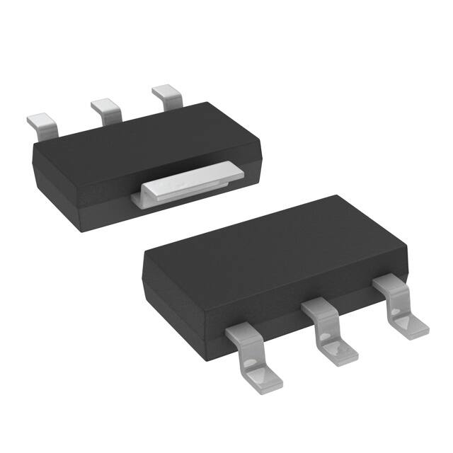
Plastic SOT-223
Plastic TO-263
DD 3-Pin
3-Pin
DT
Plastic TO-252
(D-Pak) 3-Pin
RoHS Compliant / Pb-free
Transition DC: 0522
RoHS Compliant / Pb-free
Transition DC: 0535
RoHS Compliant / Pb-free
Transition DC: 0532
LX8117-xxCST
LX8117A-xxCST
LX8117B-xxCST
LX8117-xxCDD
LX8117A-xxCDD
LX8117B-xxCDD
LX8117-xxCDT
LX8117A-xxCDT
LX8117B-xxCDT
Note: Available in Tape & Reel. Append the letter “TR” to the part number. (i.e. LX8117-00CST-TR)
Copyright © 2000
Rev. 1.5a,2005-10-25
MICROSEMI INC.
11861 WESTERN AVENUE, GARDEN GROVE, CA. 92841, 714-898-8121, FAX: 714-893-2570
1
�PRODUCT DATABOOK 1996/1997
LX8117-xx/8117A-xx/8117B-xx
0.8, 1 & 1.2A L O W D R O P O U T P O S I T I V E R E G U L AT O R S
P
R O D U C T I O N
A B S O LUT E M AXIM UM R ATINGS
D
A T A
S
H E E T
PACKAGE PIN OUTS
(Note 1)
Power Dissipation .................................................................................. Internally Limited
Input Voltage
LX8117-00/8117A-00/8117B-00 (Adj.) ..................................................................... 15V
LX8117-33/8117A-33/8117B-33 (3.3V), LX8117-05/8117A-05/8117B-05 (5.0V) .... 15V
LX8117-25/8117A-25/8117B-25 (2.5V), LX8117-28/8117A-28/8117B-28 (2.85V) .. 12V
Surge Voltage ............................................................................................................... 15V
Operating Junction Temperature
Plastic (ST, DD & DT Packages) .......................................................................... 150°C
Storage Temperature Range ...................................................................... -65°C to 150°C
Lead Temperature (Soldering, 10 seconds) ............................................................. 300°C
Short-Circuit Protection ....................................................................................... Indefinite
TAB IS V OUT
3. IN
2. OUT
1. ADJ / GND
bs
ol
et
e
ST PACKAGE
(Top View)
TAB IS VOUT
RoHS Peak Package Solder Reflow Temp. (40 seconds max. exposure)............................ 260°C (+0, -5)
Note 1. Exceeding these ratings could cause damage to the device. All voltages are with
respect to Ground. Currents are positive into, negative out of the specified terminal.
T H E R MAL DATA
ST PACKAGE:
THERMAL RESISTANCE-JUNCTION TO TAB, θJT
15°C/W
THERMAL RESISTANCE-JUNCTION TO AMBIENT, θ JA
3
IN
2
OUT
1
ADJ / GND
DD PACKAGE (D2 Pak)
(Top View)
*150°C/W
DD PACKAGE:
THERMAL RESISTANCE-JUNCTION TO TAB, θJT
10°C/W
THERMAL RESISTANCE-JUNCTION TO AMBIENT, θ JA
TAB IS V OUT
*60°C/W
3. IN
DT PACKAGE:
THERMAL RESISTANCE-JUNCTION TO TAB, θJC
2. OUT
9°C/W
THERMAL RESISTANCE-JUNCTION TO AMBIENT, θ JA
*80°C/W
1. ADJ / GND
Junction Temperature Calculation: TJ = TA + (PD x θJA). The θJA numbers are guidelines for the
thermal performance of the device/pc-board system. All of the above assume no ambient airflow.
* θ JAcan be improved with package soldered to 0.5IN2 copper area over backside ground
plane or internal power plane. θJAcan vary from 20ºC/W to > 40ºC/W depending on
mounting technique. (See Application Notes Section: Thermal Considerations)
DT PACKAGE (D-Pak)
(Top View)
RoHS / Pb-free 100% Matte Tin Lead Finish
BLOCK D IA GR A M
O
VIN
Bias
Circuit
Thermal
Limit Circuit
Bandgap
Circuit
Control
Circuit
Output
Circuit
VOUT
ADJ
2
Current
Limit Circuit
Copyright © 1999
Rev. 1.5a
�PRODUCT DATABOOK 1996/1997
LX8117-xx/8117A-xx/8117B-xx
0.8, 1 & 1.2A L O W D R O P O U T P O S I T I V E R E G U L AT O R S
P
R O D U C T I O N
D
A T A
S
H E E T
R E C O M M E N D E D O P E R AT I N G C O N D I T I O N S
Parameter
Symbol
(Note 2)
Recommended Operating Conditions
Min.
Typ.
Max.
Input Voltage
Operating Voltage
LX8117(A/B)-00 / 8117(A/B)-05
LX8117(A/B)-25 / -28 / -33
Input-Output Differential
LX8117(A/B)-00
Operating Ambient Temperature Range
Units
15
12
10
125
0
V
V
V
°C
bs
ol
et
e
Note 2. Range over which the device is functional.
ELECTRICAL CHARACTERISTICS
(Unless otherwise specified: 0°C ≤ TJ ≤ 125°C, IMAX = 0.8A for the LX8117-xx, I MAX = 1.0A for the LX8117A-xx, and IMAX = 1.2A for the LX8117B-xx.)
LX8117-00 / 8117A-00 / 8117B-00 (Adjustable)
Parameter
Reference Voltage
Line Regulation (Note 3)
Load Regulation (Note 3)
Dropout Voltage
(Note 4)
LX8117-00
LX8117A/B-00
Current Limit
LX8117-00
LX8117A-00
LX8117B-00
Minimum Load Current (Note 5)
Thermal Regulation
Ripple Rejection
Adjust Pin Current
Adjust Pin Current Change
Temperature Stability
Long Term Stability
RMS Output Noise (% of VOUT)
Symbol
Test Conditions
VREF
IOUT = 10mA, (VIN - VOUT) = 2V, TJ = 25°C
10mA ≤ IOUT ≤ IOUT (MAX), 1.4V ≤ (VIN - VOUT ) ≤ 10V
∆VREF(VIN) IOUT = 10mA, 1.5V ≤ (VIN - VOUT ) ≤ 7V
∆VREF (IOUT) (VIN - VOUT) = 3V, 10mA ≤ IOUT ≤ IOUT (MAX)
∆V
IOUT = 100mA
IOUT = 500mA
IOUT = IOUT (MAX)
I OUT = IOUT (MAX)
IOUT (MAX) (VIN - VOUT) = 5V, TJ = 25°C
(VIN - VOUT) = 5V, TJ = 25°C
(VIN - VOUT) = 5V, TJ = 25°C
I OUT (MIN) VIN ≤ 10V
∆VOUT (Pwr) TA = 25°C, 30ms pulse
fRIPPLE =120Hz, (VIN - V OUT) = 3V, VRIPPLE = 1Vp-p
I ADJ
∆IADJ
10mA ≤ IOUT ≤ IOUT (MAX) , 1.4V ≤ (VIN - VOUT) ≤ 10V
∆VOUT (T)
∆VOUT (t) TA = 125°C, 1000 hours
VOUT (RMS) 10Hz ≤ f ≤ 10kHz
LX8117 / 17A / 17B-00
Min. Typ.
Max.
1.238
1.225
800
1000
1200
60
1.250
1.250
0.05
0.15
0.97
1.00
1.05
1.15
950
1200
1500
0.5
0.08
75
45
0.2
0.5
0.3
0.003
1.262
1.270
0.2
0.4
1.10
1.15
1.20
1.30
5
0.2
100
5
Units
V
V
%
%
V
V
V
V
mA
mA
mA
mA
%/W
dB
µA
µA
%
%
%
O
Notes: 3. See thermal regulation specification for changes in output voltage due to heating effects. Load regulation and line regulation are measured at a constant junction
temperature by low duty cycle pulse testing.
4. Dropout voltage is specified over the full output current range of the device. Dropout voltage is defined as the minimum input/output differential measured
at the specified output current. Test points and limits are also shown on the Dropout Voltage Curve.
5. Minimum load current is defined as the minimum output current required to maintain regulation.
Copyright © 1999
Rev. 1.5a
(Other Voltage Options on following pages.)
3
�PRODUCT DATABOOK 1996/1997
LX8117-xx/8117A-xx/8117B-xx
0.8, 1 & 1.2A L O W D R O P O U T P O S I T I V E R E G U L AT O R S
P
R O D U C T I O N
D
A T A
S
H E E T
ELECTRICAL CHARACTERISTICS
(continued)
LX8117-25 / 8117A-25 / 8117B-25 (2.5V Fixed)
Parameter
Output Voltage
Symbol
Test Conditions
VOUT
2.475
2.450
2.500
2.500
1
2
0.97
1.00
1.05
1.15
950
1200
1500
4.5
0.08
75
0.5
0.3
0.003
2.525
2.550
6
10
1.10
1.15
1.20
1.30
bs
ol
et
e
Line Regulation (Note 3)
Load Regulation (Note 3)
Dropout Voltage
(Note 4)
IOUT = 10mA, VIN = 5V, TA = 25°C
0mA ≤ IOUT ≤ IOUT (MAX) , 4.75V ≤ VIN ≤ 10V
∆V OUT(VIN) IOUT = 0mA, 4.25V ≤ VIN ≤ 10V
∆VOUT (IOUT) VIN = 4.25V, 0mA ≤ IOUT ≤ IOUT (MAX)
∆V
IOUT = 100mA
IOUT = 500mA
IOUT = IOUT (MAX)
I OUT = IOUT (MAX)
IOUT (MAX) (VIN - VOUT) = 5V, TJ = 25°C
(VIN - VOUT) = 5V, TJ = 25°C
(VIN - VOUT) = 5V, TJ = 25°C
IQ
VIN ≤ 10V
∆VOUT (Pwr) TA = 25°C, 30ms pulse
fRIPPLE =120Hz, (VIN - V OUT) = 3V, VRIPPLE = 1Vp-p
∆VOUT (T)
∆VOUT (t) TA = 125°C, 1000 hours
VOUT (RMS) 10Hz ≤ f ≤ 10kHz
LX8117 / 17A / 17B-25
Min. Typ.
Max.
Current Limit
LX8117-25
LX8117A/B-25
LX8117-25
LX8117A-25
LX8117B-25
Quiescent Current
Thermal Regulation
Ripple Rejection
Temperature Stability
Long Term Stability
RMS Output Noise (% of VOUT)
800
1000
1200
60
10
0.2
Units
V
V
mV
mV
V
V
V
V
mA
mA
mA
mA
%/W
dB
%
%
%
LX8117-28 / 8117A-28 / 8117B-28 (2.8V Fixed)
Parameter
Output Voltage
VOUT
Line Regulation (Note 3)
Load Regulation (Note 3)
Dropout Voltage
(Note 4)
LX8117-28
LX8117A/B-28
LX8117-28
LX8117A-28
LX8117B-28
Quiescent Current
Thermal Regulation
Ripple Rejection
Temperature Stability
Long Term Stability
RMS Output Noise (% of VOUT)
Test Conditions
IOUT = 10mA, VIN = 4.85V, TA = 25°C
0mA ≤ IOUT ≤ IOUT (MAX) , 4.25V ≤ VIN ≤ 10V
0mA ≤ IOUT ≤ 500mA, VIN = 3.95V
∆V OUT(VIN) IOUT = 0mA, 4.25V ≤ VIN ≤ 10V
∆VOUT (IOUT) VIN = 4.25V, 0mA ≤ IOUT ≤ IOUT (MAX)
∆V
IOUT = 100mA
IOUT = 500mA
IOUT = IOUT (MAX)
I OUT = IOUT (MAX)
IOUT (MAX) (VIN - VOUT) = 5V, TJ = 25°C
(VIN - VOUT) = 5V, TJ = 25°C
(VIN - VOUT) = 5V, TJ = 25°C
IQ
VIN ≤ 10V
∆VOUT (Pwr) TA = 25°C, 30ms pulse
fRIPPLE =120Hz, (VIN - V OUT) = 3V, VRIPPLE = 1Vp-p
∆VOUT (T)
∆VOUT (t) TA = 125°C, 1000 hours
VOUT (RMS) 10Hz ≤ f ≤ 10kHz
O
Current Limit
Symbol
LX8117 / 17A / 17B-28
Min. Typ.
Max.
2.820
2.790
2.790
800
1000
1200
60
2.850
2.850
2.850
1
2
0.97
1.00
1.05
1.15
950
1200
1500
4.5
0.08
75
0.5
0.3
0.003
2.880
2.910
2.910
6
10
1.10
1.15
1.20
1.30
10
0.2
Units
V
V
V
mV
mV
V
V
V
V
mA
mA
mA
mA
%/W
dB
%
%
%
Notes: 3. See thermal regulation specification for changes in output voltage due to heating effects. Load regulation and line regulation are measured at a constant junction
temperature by low duty cycle pulse testing.
4. Dropout voltage is specified over the full output current range of the device. Dropout voltage is defined as the minimum input/output differential measured
at the specified output current. Test points and limits are also shown on the Dropout Voltage Curve.
5. Minimum load current is defined as the minimum output current required to maintain regulation.
4
Copyright © 1999
Rev. 1.5a
�PRODUCT DATABOOK 1996/1997
LX8117-xx/8117A-xx/8117B-xx
0.8, 1 & 1.2A L O W D R O P O U T P O S I T I V E R E G U L AT O R S
P
R O D U C T I O N
D
A T A
S
H E E T
ELECTRICAL CHARACTERISTICS
(continued)
LX8117-33 / 8117A-33 / 8117B-33 (3.3V Fixed)
Parameter
Output Voltage
Symbol
Test Conditions
V OUT
3.267
3.235
3.300
3.300
1
2
0.97
1.00
1.05
1.15
950
1200
1500
4.5
0.08
75
0.5
0.3
0.003
3.333
3.365
6
10
1.10
1.15
1.20
1.30
bs
ol
et
e
Line Regulation (Note 3)
Load Regulation (Note 3)
Dropout Voltage
(Note 4)
IOUT = 10mA, VIN = 5V, TA = 25°C
0mA ≤ IOUT ≤ IOUT (MAX) , 4.75V ≤ VIN ≤ 10V
∆V OUT(VIN) IOUT = 0mA, 4.25V ≤ VIN ≤ 10V
∆V OUT (IOUT) VIN = 4.25V, 0mA ≤ IOUT ≤ IOUT (MAX)
∆V
IOUT = 100mA
IOUT = 500mA
IOUT = IOUT (MAX)
IOUT = IOUT (MAX)
I OUT (MAX) (VIN - VOUT ) = 5V, TJ = 25°C
(VIN - VOUT ) = 5V, TJ = 25°C
(VIN - VOUT ) = 5V, TJ = 25°C
IQ
VIN ≤ 10V
∆V OUT (Pwr) TA = 25°C, 30ms pulse
fRIPPLE =120Hz, (VIN - VOUT ) = 3V, VRIPPLE = 1Vp-p
∆VOUT (T)
∆VOUT (t) TA = 125°C, 1000 hours
VOUT (RMS) 10Hz ≤ f ≤ 10kHz
LX8117 / 17A / 17B-33
Min.
Typ.
Max.
Current Limit
LX8117-33
LX8117A/B-33
LX8117-33
LX8117A-33
LX8117B-33
Quiescent Current
Thermal Regulation
Ripple Rejection
Temperature Stability
Long Term Stability
RMS Output Noise (% of VOUT)
800
1000
1200
60
10
0.2
Units
V
V
mV
mV
V
V
V
V
mA
mA
mA
mA
%/W
dB
%
%
%
LX8117-05 / 8117A-05 / 8117B-05 (5.0V Fixed)
Parameter
Output Voltage
V OUT
Line Regulation (Note 3)
Load Regulation (Note 3)
Dropout Voltage
(Note 4)
LX8117-05
LX8117A/B-05
LX8117-05
LX8117A-05
LX8117B-05
Quiescent Current
Thermal Regulation
Ripple Rejection
Temperature Stability
Long Term Stability
RMS Output Noise (% of VOUT)
Test Conditions
IOUT = 10mA, VIN = 7V, TA = 25°C
0mA ≤ IOUT ≤ IOUT (MAX) , 6.50V ≤ VIN ≤ 10V
∆V OUT(VIN) IOUT = 0mA, 6.5V ≤ VIN ≤ 10V
∆V OUT (IOUT) VIN = 6.5V, 0mA ≤ IOUT ≤ IOUT (MAX)
∆V
IOUT = 100mA
IOUT = 500mA
IOUT = IOUT (MAX)
IOUT = IOUT (MAX)
I OUT (MAX) (VIN - VOUT ) = 5V, TJ = 25°C
(VIN - VOUT ) = 5V, TJ = 25°C
(VIN - VOUT ) = 5V, TJ = 25°C
IQ
VIN ≤ 10V
∆V OUT (Pwr) TA = 25°C, 30ms pulse
fRIPPLE =120Hz, (VIN - VOUT ) = 3V, VRIPPLE = 1Vp-p
∆VOUT (T)
∆VOUT (t) TA = 125°C, 1000 hours
VOUT (RMS) 10Hz ≤ f ≤ 10kHz
O
Current Limit
Symbol
LX8117 / 17A / 17B-05
Min.
Typ.
Max.
4.950
4.900
800
1000
1200
60
5.000
5.000
1
2.5
0.97
1.00
1.05
1.15
950
1200
1500
4.5
0.08
75
0.5
0.3
0.003
5.050
5.100
10
15
1.10
1.15
1.20
1.30
10
0.2
Units
V
V
mV
mV
V
V
V
V
mA
mA
mA
mA
%/W
dB
%
%
%
Notes: 3. See thermal regulation specification for changes in output voltage due to heating effects. Load regulation and line regulation are measured at a constant junction
temperature by low duty cycle pulse testing.
4. Dropout voltage is specified over the full output current range of the device. Dropout voltage is defined as the minimum input/output differential measured
at the specified output current. Test points and limits are also shown on the Dropout Voltage Curve.
5. Minimum load current is defined as the minimum output current required to maintain regulation.
Copyright © 1999
Rev. 1.5a
5
�PRODUCT DATABOOK 1996/1997
LX8117-xx/8117A-xx/8117B-xx
0.8, 1 & 1.2A L O W D R O P O U T P O S I T I V E R E G U L AT O R S
P
R O D U C T I O N
D
A T A
S
H E E T
A P P L I C AT I O N N O T E S
Power Supply
IN
LX8117-xx
OUT
Minumum Load
(Larger resistor)
Full Load
(Smaller resistor)
ADJ
C1
C2
Star Ground
RDSON