21653C.book Page 1 Thursday, January 10, 2013 12:55 PM
MCP1525/41
2.5V and 4.096V Voltage References
Features
Description
•
•
•
•
•
•
•
•
The Microchip Technology Inc. MCP1525/41 devices
are 2.5V and 4.096V precision voltage references that
use a combination of an advanced CMOS circuit
design and EPROM trimming to provide an initial
tolerance of ±1% (max.) and temperature stability of
±50 ppm/°C (max.). In addition to a low quiescent
current of 100 µA (max.) at 25°C, these devices offer a
clear advantage over the traditional Zener techniques
in terms of stability across time and temperature. The
output voltage is 2.5V for the MCP1525 and 4.096V for
the MCP1541. These devices are offered in SOT-23-3
and TO-92 packages, and are specified over the
industrial temperature range of -40°C to +85°C.
•
•
•
•
•
•
•
•
•
•
Battery-powered Systems
Handheld Instruments
Instrumentation and Process Control
Test Equipment
Data Acquisition Systems
Communications Equipment
Medical Equipment
Precision Power supplies
8-bit, 10-bit, 12-bit A/D Converters (ADCs)
D/A Converters (DACs)
Typical Application Circuit
Temperature Drift
2.525
2.520
2.515
2.510
2.505
2.500
2.495
2.490
2.485
2.480
2.475
VDD
CIN
0.1 µF
(optional)
VREF
MCP1525
MCP1541
VIN
VSS
VOUT
4.140
4.130
4.120
4.110
MCP1541
4.100
4.090
4.080
MCP1525
4.070
4.060
4.050
4.040
-50 -25 0
25 50 75 100
Ambient Temperature (°C)
Package Types
MCP1525
MCP1541
TO-92
MCP1525
MCP1541
SOT-23-3
VIN 1
CL
1 µF to 10 µF
3 VSS
VOUT 2
Basic Configuration
VSS
2001-2012 Microchip Technology Inc.
MCP1541 Output Voltage
(V)
Applications
MCP1525 Output Voltage
(V)
Precision Voltage Reference
Output Voltages: 2.5V and 4.096V
Initial Accuracy: ±1% (max.)
Temperature Drift: ±50 ppm/°C (max.)
Output Current Drive: ±2 mA
Maximum Input Current: 100 µA @ +25°C (max.)
Packages: TO-92 and SOT-23-3
Industrial Temperature Range: -40°C to +85°C
123
VOUT
VIN
DS21653C-page 1
�21653C.book Page 2 Thursday, January 10, 2013 12:55 PM
MCP1525/41
1.0
ELECTRICAL
CHARACTERISTICS
† Notice: Stresses above those listed under “Absolute
Maximum Ratings” may cause permanent damage to the
device. This is a stress rating only and functional operation of
the device at those or any other conditions above those
indicated in the operational listings of this specification is not
implied. Exposure to maximum rating conditions for extended
periods may affect device reliability.
Absolute Maximum Ratings †
VIN – VSS ..........................................................................7.0V
Input Current (VIN) .......................................................20 mA
Output Current (VOUT) .............................................. ±20 mA
Continuous Power Dissipation (TA = 125°C)............. 140 mW
All Inputs and Outputs .....................VSS – 0.6V to VIN + 1.0V
Storage Temperature.....................................-65°C to +150°C
Maximum Junction Temperature (TJ) .......................... +125°C
ESD protection on all pins (HBM) 4 kV
DC ELECTRICAL SPECIFICATIONS
Electrical Characteristics: Unless otherwise indicated, TA = +25°C, VIN = 5.0V, VSS = GND, IOUT = 0 mA and CL = 1 µF.
Parameter
Sym
Min
Typ
Max
Units
Conditions
Output Voltage, MCP1525
VOUT
2.475
2.5
2.525
V
2.7V VIN 5.5V
Output Voltage, MCP1541
VOUT
4.055
4.096
4.137
V
4.3V VIN 5.5V
TCVOUT
—
27
50
ppm/°C
TA = -40°C to 85°C (Note 1)
VOUT
—
2
—
ppm/hr
Exposed 1008 hrs @ +125°C
(see Figure 1-1), measured @ +25°C
Output
Output Voltage Drift
Long-Term Output Stability
VOUT/IOUT
—
0.5
1
mV/mA
IOUT = 0 mA to -2 mA
VOUT/IOUT
—
0.6
1
mV/mA
IOUT = 0 mA to 2 mA
VOUT/IOUT
—
—
1.3
mV/mA
IOUT = 0 mA to -2 mA,
TA = -40°C to 85°C
VOUT/IOUT
—
—
1.3
mV/mA
IOUT = 0 mA to 2 mA,
TA = -40°C to 85°C
VHYS
—
115
—
ppm
Note 2
ISC
—
±8
—
mA
TA = -40°C to 85°C, VIN = 5.5V
Dropout Voltage
VDROP
—
137
—
mV
Line Regulation
VOUT/VIN
—
107
300
µV/V
VIN = 2.7V to 5.5V for MCP1525,
VIN = 4.3V to 5.5V for MCP1541
VOUT/VIN
—
—
350
µV/V
VIN = 2.7V to 5.5V for MCP1525,
VIN = 4.3V to 5.5V for MCP1541,
TA = -40°C to 85°C
Input Voltage, MCP1525
VIN
2.7
—
5.5
V
TA = -40°C to 85°C
Input Voltage, MCP1541
VIN
4.3
—
5.5
V
TA = -40°C to 85°C
Input Current
IIN
—
86
100
µA
No load
IIN
—
95
120
µA
No load, TA = -40°C to 85°C
Load Regulation
Output Voltage Hysteresis
Maximum Load Current
Input-to-Output
IOUT = 2 mA
Input
Note 1:
2:
Output temperature coefficient is measured using a “box” method, where the +25°C output voltage is trimmed as close
to typical as possible. The 85°C output voltage is then again trimmed to zero out the tempco.
Output Voltage Hysteresis is defined as the change in output voltage measured at +25°C before and after cycling the
temperature to +85°C and -40°C; refer to Section 1.1.10 “Output Voltage Hysteresis”.
DS21653C-page 2
2001-2012 Microchip Technology Inc.
�21653C.book Page 3 Thursday, January 10, 2013 12:55 PM
MCP1525/41
AC ELECTRICAL SPECIFICATIONS
Electrical Characteristics: Unless otherwise indicated, TA = +25°C, VIN = 5.0V, VSS = GND, IOUT = 0 mA and CL = 1 µF.
Parameter
Sym
Min
Typ
Max
Units
BW
—
100
—
kHz
Conditions
AC Response
Bandwidth
Input and Load Capacitors (see Figure 4-1)
Input Capacitor
CIN
—
0.1
—
µF
Notes 1
Load Capacitor
CL
1
—
10
µF
Notes 2
Eno
—
90
—
µVP-P
0.1 Hz to 10 Hz
Eno
—
500
—
µVP-P
10 Hz to 10 kHz
Eno
—
145
—
µVP-P
0.1 Hz to 10 Hz
Eno
—
700
—
µVP-P
10 Hz to 10 kHz
Noise
MCP1525 Output Noise Voltage
MCP1541 Output Noise Voltage
Note 1:
2:
The input capacitor is optional; Microchip recommends using a ceramic capacitor.
These parts are tested at both 1 µF and 10 µF to ensure proper operation over this range of load capacitors. A wider
range of load capacitor values has been characterized successfully, but is not tested in production.
TEMPERATURE SPECIFICATIONS
Electrical Characteristics: Unless otherwise indicated, TA = +25°C, VIN = 5.0V and VSS = GND.
Parameter
Sym
Min
Typ
Max
Units
Conditions
Temperature Ranges
Specified Temperature Range
TA
-40
—
+85
°C
Operating Temperature Range
TA
-40
—
+125
°C
Storage Temperature Range
TA
-65
—
+150
°C
Thermal Resistance, TO-92
JA
—
132
—
°C/W
Thermal Resistance, SOT-23-3
JA
—
336
—
°C/W
Note 1
Thermal Package Resistances
Note 1:
1.1
These voltage references operate over the Operating Temperature Range, but with reduced performance. In any case,
the internal Junction Temperature (TJ) must not exceed the Absolute Maximum specification of +150°C.
Specification Descriptions and
Test Circuits
1.1.3
OUTPUT VOLTAGE DRIFT (TCVOUT)
Output voltage is the reference voltage that is available
on the output pin (VOUT).
The output temperature coefficient or voltage drift is a
measure of how much the output voltage (VOUT) will
vary from its initial value with changes in ambient
temperature. The value specified in the electrical
specifications is measured and equal to:
1.1.2
EQUATION 1-1:
1.1.1
OUTPUT VOLTAGE
INPUT VOLTAGE
The input (operating) voltage is the range of voltage
that can be applied to the VIN pin and still have the
device produce the designated output voltage on the
VOUT pin.
V OUT V NO M
TCVO UT = -----------------------------------T A
ppm C
Where:
VNOM = 2.5V, MCP1525
VNOM = 4.096V, MCP1541
2001-2012 Microchip Technology Inc.
DS21653C-page 3
�21653C.book Page 4 Thursday, January 10, 2013 12:55 PM
MCP1525/41
1.1.4
DROPOUT VOLTAGE
1.1.9
The dropout voltage of these devices is measured by
reducing VIN to the point where the output drops by 1%.
Under these conditions the dropout voltage is equal to:
EQUATION 1-2:
V D RO P = V IN – V O UT
The dropout voltage is affected
temperature and load current.
by
ambient
LINE REGULATION
Line regulation is a measure of the change in output
voltage (VOUT) as a function of a change in the input
voltage (VIN). This is expressed as VOUT/VIN and is
measured in either µV/V or ppm. For example, a 1 µV
change in VOUT caused by a 500 mV change in VIN
would net a VOUT/VIN of 2 µV/V, or 2 ppm.
1.1.6
The long-term output stability is measured by exposing
the devices to an ambient temperature of 125°C
(Figure 2-9) while configured in the circuit shown in
Figure 1-1. In this test, all electrical specifications of the
devices are measured periodically at +25°C.
VIN = 5.5V
In Figure 2-18, the dropout voltage is shown over a
negative and positive range of output current. For
currents above zero milliamps, the dropout voltage is
positive. In this case, the voltage reference is primarily
powered by VIN. With output currents below zero
milliamps, the dropout voltage is negative. As the
output current becomes more negative, the input
current (IIN) reduces. Under this condition, the output
current begins to provide the needed power to the
voltage reference.
1.1.5
LONG-TERM OUTPUT STABILITY
MCP1525
MCP1541
VIN
RL
VOUT
VSS
FIGURE 1-1:
Configuration.
1.1.10
CL
1 µF
±2 mA
square wave
@ 10 Hz
Dynamic Life Test
OUTPUT VOLTAGE HYSTERESIS
The output voltage hysteresis is a measure of the
output voltage error once the powered devices are
cycled over the entire operating temperature range.
The amount of hysteresis can be quantified by
measuring the change in the +25°C output voltage after
temperature excursions from +25°C to +85°C to +25°C
and also from +25°C to -40°C to +25°C.
LOAD REGULATION (VOUT/IOUT)
Load regulation is a measure of the change in the
output voltage (VOUT) as a function of the change in
output current (IOUT). Load regulation is usually
measured in mV/mA.
1.1.7
INPUT CURRENT
The input current (operating current) is the current that
sinks from VIN to VSS without a load current on the output pin. This current is affected by temperature and the
output current.
1.1.8
INPUT VOLTAGE REJECTION
RATIO
The Input Voltage Rejection Ratio (IVRR) is a measure
of the change in output voltage versus the change in
input voltage over frequency, as shown in Figure 2-7.
The calculation used for this plot is:
EQUATION 1-3:
V IN
IVRR = 20 log ------------V O UT
DS21653C-page 4
dB
2001-2012 Microchip Technology Inc.
�21653C.book Page 5 Thursday, January 10, 2013 12:55 PM
MCP1525/41
2.0
TYPICAL PERFORMANCE CURVES
Note:
The graphs and tables provided following this note are a statistical summary based on a limited number of
samples and are provided for informational purposes only. The performance characteristics listed herein
are not tested or guaranteed. In some graphs or tables, the data presented may be outside the specified
operating range (e.g., outside specified power supply range) and therefore outside the warranted range.
4.140
4.130
4.120
4.110
MCP1541
4.100
4.090
4.080
MCP1525
4.070
4.060
4.050
4.040
-50 -25 0
25 50 75 100
Ambient Temperature (°C)
1.0
0.9
0.8
0.7
0.6
0.5
0.4
0.3
0.2
0.1
0.0
Output Voltage vs. Ambient
Sink Current =
0 mA to -2 mA
0
25
50
75
Ambient Temperature (°C)
100
MCP1525
FIGURE 2-3:
Temperature.
-25
0
25
50
75
Ambient Temperature (°C)
100
Input Current vs. Ambient
2001-2012 Microchip Technology Inc.
MCP1541
VIN = 4.3V to 5.5V
40
20
-25
0
25
50
75
Ambient Temperature (°C)
FIGURE 2-4:
Temperature.
100
Line Regulation vs. Ambient
MCP1525 and MCP1541
6
5
4
3
IOUT = +2 mA
2
1
IOUT = -2 mA
0
1
10
100 1.E+03
1k
10k 1.E+05
100k 1.E+06
1M
1.E+00
1.E+01
1.E+02
1.E+04
Frequency (Hz)
FIGURE 2-5:
Frequency.
MCP1541
-50
60
Output Noise Voltage Density
(μV/Hz)
Input Current (µA)
FIGURE 2-2:
Load Regulation vs.
Ambient Temperature.
100
90
80
70
60
50
40
30
20
10
0
80
7
Source Current =
0 mA to 2 mA
-25
100
-50
MCP1525 and MCP1541
-50
MCP1525
VIN = 2.7V to 5.5V
120
0
Output Impedance (:)
Load Regulation (mV/mA)
FIGURE 2-1:
Temperature.
140
Line Regulation (µV/V)
2.525
2.520
2.515
2.510
2.505
2.500
2.495
2.490
2.485
2.480
2.475
MCP1541 Output Voltage
(V)
MCP1525 Output Voltage
(V)
Note: Unless otherwise indicated, TA = +25°C, VIN = 5.0V, VSS = GND, IOUT = 0 mA and CL = 1 µF.
Output Impedance vs.
1,000
MCP1541
100
MCP1525
10
1
0.1
1
10
100
1k
Frequency (Hz)
10k
100k
FIGURE 2-6:
Output Noise Voltage
Density vs. Frequency.
DS21653C-page 5
�21653C.book Page 6 Thursday, January 10, 2013 12:55 PM
MCP1525/41
4.0975
90
Output Voltage (V)
70
MCP1541
60
50
40
30
1
1.E+00
10
1.E+01
100
1k
1.E+02 1.E+03
Frequency (Hz)
10k
1.E+04
4.098
2.505
4.097
2.504
MCP1525 Output
Voltage (V)
4.096
IOUT = +2 mA
IOUT = 0 mA
IOUT = -2 mA
2.503
2.502
4.095
4.094
2.501
4.093
2.500
4.092
2.499
4.091
2.498
MCP1541 Output
Voltage (V)
2.506
Output Voltage vs. Input
Life Test (TA = +125°C)
+3
Average
-3
0
200
400
600
Time (hr)
800
1000
FIGURE 2-9:
Output Voltage Aging vs.
Time (MCP1525 Device Life Test data)
DS21653C-page 6
4.0955
1.5
2.0
MCP1525
2.5010
2.5005
2.5000
2.4995
2.4990
-2.0 -1.5 -1.0 -0.5 0.0 0.5 1.0
Output Current (mA)
4.090
MCP1525
600 Samples
4.0960
2.5015
1.5
2.0
FIGURE 2-11:
MCP1525 Output Voltage
vs. Output Current.
Maximum Load Current (mA)
10
8
6
4
2
0
-2
-4
-6
-8
-10
4.0965
FIGURE 2-10:
MCP1541 Output Voltage
vs. Output Current.
2.5 3.0 3.5 4.0 4.5 5.0 5.5
Input Voltage (V)
FIGURE 2-8:
Voltage.
4.0970
4.0950
-2.0 -1.5 -1.0 -0.5 0.0 0.5 1.0
Output Current (mA)
100k
1.E+05
FIGURE 2-7:
Input Voltage Rejection
Ratio vs. Frequency.
Output Voltage Aging (mV)
MCP1541
MCP1525
80
Output Voltage (V)
Input Voltage Rejection Ratio
(dB)
Note: Unless otherwise indicated, TA = +25°C, VIN = 5.0V, VSS = GND, IOUT = 0 mA and CL = 1 µF.
10.0
Sink
9.5
MCP1541
9.0
MCP1525
8.5
8.0
7.5
Source
MCP1541
7.0
2.5
FIGURE 2-12:
Input Voltage
3.0
3.5
4.0
4.5
Input Voltage (V)
5.0
5.5
Maximum Load Current vs.
2001-2012 Microchip Technology Inc.
�21653C.book Page 7 Thursday, January 10, 2013 12:55 PM
MCP1525/41
MCP1541
MCP1525
3.0
FIGURE 2-13:
Voltage.
5.0
5.5
VOUT
MCP1525
Time (100 µs/div)
Input Current vs. Input
Bandwidth = 0.1 Hz to 10 Hz
Eno = 22 µVRMS = 145 µVP-P
Output Noise Voltage
(20 µV/div)
MCP1541
3.5
4.0
4.5
Input Voltage (V)
FIGURE 2-16:
Response.
6.0
5.5
5.0
4.5
4.0
3.5
3.0
2.5
2.0
1.5
1.0
0.5
0.0
VOUT
MCP1525
FIGURE 2-17:
Response.
6
Voltage (V)
VOUT, MCP1541
3
VOUT, MCP1525
2
1
0
Dropout Voltage (mV)
150
VIN
4
MCP1525 and MCP1541
50
0
-50
-100
-1.5
Time (200 µs/div)
Turn-on Transient Time.
2001-2012 Microchip Technology Inc.
MCP1525 Line Transient
100
-150
-2.0
-1
FIGURE 2-15:
16
14
12
10
8
6
4
2
0
-2
-4
-6
-8
Time (100 µs/div)
MCP1541 0.1 Hz to 10 Hz
5
MCP1525 Load Transient
VIN
Time (1 s/div)
FIGURE 2-14:
Output Noise.
35
30
25
20
15
10
5
0
-5
-10
-15
-20
IOUT
Change in
Output Voltage (mV)
2.5
4
2
0
-2
-4
-6
-8
-10
-12
-14
-16
-18
Change in
Output Voltage (mV)
Output Current (mA)
100
90
80
70
60
50
40
30
20
10
0
Input Voltage (V)
Input Current (µA)
Note: Unless otherwise indicated, TA = +25°C, VIN = 5.0V, VSS = GND, IOUT = 0 mA and CL = 1 µF.
FIGURE 2-18:
Current.
-1.0 -0.5 0.0 0.5 1.0
Output Current (mA)
1.5
2.0
Dropout Voltage vs. Output
DS21653C-page 7
�21653C.book Page 8 Thursday, January 10, 2013 12:55 PM
MCP1525/41
3.0
PIN DESCRIPTIONS
Descriptions of the pins are listed in Table 3-1.
TABLE 3-1:
PIN FUNCTION TABLE.
MCP1525, MCP1541
(TO-92-3)
MCP1525, MCP1541
(SOT-23-3)
3
1
VIN
2
2
VOUT
1
3
VSS
3.1
Input Voltage (VIN)
VIN functions as the positive power supply input (or
operating input). An optional 0.1 µF ceramic capacitor
can be placed at this pin if the input voltage is too noisy;
it needs to be within 5 mm of this pin. The input voltage
needs to be at least 0.2V higher than the output voltage
for normal operation.
3.2
Symbol
Description
Input Voltage (or Positive Power Supply)
Output Voltage (or Reference Voltage)
Ground (or Negative Power Supply)
3.3
Ground (VSS)
Normally connected directly to ground. It can be placed
at another voltage as long as all of the voltages shift
with it, and proper bypassing is observed.
Output Voltage (VOUT)
VOUT is an accurate reference voltage output. It can
source and sink small currents, and has a low output
impedance. A load capacitor between 1 µF and 10 µF
needs to be located within 5 mm of this pin.
DS21653C-page 8
2001-2012 Microchip Technology Inc.
�21653C.book Page 9 Thursday, January 10, 2013 12:55 PM
MCP1525/41
4.0
APPLICATIONS INFORMATION
4.1.4
4.1
Application Tips
Mechanical stress due to Printed Circuit Board (PCB)
mounting can cause the output voltage to shift from its
initial value. Devices in the SOT-23-3 package are
generally more prone to assembly stress than devices
in the TO-92 package. To reduce stress-related output
voltage shifts, mount the reference on low-stress areas
of the PCB (i.e., away from PCB edges, screw holes
and large components).
4.1.1
BASIC CIRCUIT CONFIGURATION
The MCP1525 and MCP1541 voltage reference
devices should be applied as shown in Figure 4-1 in all
applications.
VDD
MCP1525
MCP1541
CIN
VIN
0.1 µF
(optional)
VREF
VSS
VOUT
CL
1 µF to 10 µF
FIGURE 4-1:
Basic Circuit Configuration.
As shown in Figure 4-1, the input voltage is connected
to the device at the VIN input, with an optional 0.1 µF
ceramic capacitor. This capacitor would be required if
the input voltage has excess noise. A 0.1 µF capacitor
would reject input voltage noise at approximately
1 to 2 MHz. Noise below this frequency will be amply
rejected by the input voltage rejection of the voltage reference. Noise at frequencies above 2 MHz will be
beyond the bandwidth of the voltage reference and,
consequently, not transmitted from the input pin
through the device to the output.
The load capacitance (CL) is required in order to
stabilize the voltage reference; see Section 4.1.3
“Load Capacitor”.
4.1.2
INPUT (BYPASS) CAPACITOR
The MCP1525 and MCP1541 voltage references do
not require an input capacitor across VIN to VSS.
However, for added stability and input voltage transient
noise reduction, a 0.1 µF ceramic capacitor is
recommended, as shown in Figure 4-1. This capacitor
should be close to the device (within 5 mm of the pin).
4.1.3
LOAD CAPACITOR
PRINTED CIRCUIT BOARD LAYOUT
CONSIDERATIONS
4.1.5
OUTPUT FILTERING
If the noise at the output of these voltage references is
too high for the particular application, it can be easily
filtered with an external RC filter and op amp buffer.
The op amp’s input and output voltage ranges need to
include the reference output voltage.
VDD
MCP1525
MCP1541
VIN
VDD
RFIL
10 kW
VOUT
VSS
CL
10 µF
VREF
CFIL
1 µF
MCP6021
FIGURE 4-2:
Filter.
Output Noise-Reducing
The RC filter values are selected for a desired cutoff
frequency:
EQUATION 4-1:
1
f C = -----------------------------2R FIL C FIL
The values that are shown in Figure 4-2 (10 k and
1 µF) will create a first-order, low-pass filter at the
output of the amplifier. The cutoff frequency of this filter
is 15.9 Hz, and the attenuation slope is 20 dB/decade.
The MCP6021 amplifier isolates the loading of this lowpass filter from the remainder of the application circuit.
This amplifier also provides additional drive, with a
faster response time than the voltage reference.
The output capacitor from VOUT to VSS acts as a
frequency compensation for the references and cannot
be omitted. Use load capacitors between 1 µF and
10 µF to compensate these devices. A 10 µF output
capacitor has slightly better noise, and provides
additional charge for fast load transients, when
compared to a 1 µF output capacitor. This capacitor
should be close to the device (within 5 mm of the pin).
2001-2012 Microchip Technology Inc.
DS21653C-page 9
�21653C.book Page 10 Thursday, January 10, 2013 12:55 PM
MCP1525/41
4.2
Typical Application Circuits
4.2.1
NEGATIVE VOLTAGE REFERENCE
A negative precision voltage reference can be
generated by using the MCP1525 or MCP1541 in the
configuration shown in Figure 4-3.
4.2.2
The MCP1525 and MCP1541 were carefully designed
to provide a voltage reference for Microchip’s 10-bit
and 12-bit families of ADCs. The circuit shown in
Figure 4-4 shows a MCP1541 configured to provide the
reference to the MCP3201, a 12-bit ADC.
VDD = 5.0V
R2
10 k
0.1%
MCP1541
R1
10 k
0.1%
VOUT
CL
10 µF
VSS
VDD = 5.0V
CIN
0.1 µF
MCP1525
MCP1541
VIN
A/D CONVERTER REFERENCE
CL
10 µF
VIN
10 µF
VOUT
VSS
VREF
VREF
MCP606
VIN
0.1 µF
IN+
MCP3201
VSS = - 5.0V
IN–
3
to PIC®
Microcontroller
VREF = -2.5V, MCP1525
VREF = -4.096V, MCP1541
FIGURE 4-3:
Reference.
Negative Voltage
FIGURE 4-4:
ADC Reference Circuit.
In this circuit, the voltage inversion is implemented
using the MCP606 and two equal resistors. The voltage
at the output of the MCP1525 or MCP1541 voltage
reference drives R1, which is connected to the inverting
input of the MCP606 amplifier. Since the non-inverting
input of the amplifier is biased to ground, the inverting
input will also be close to ground potential. The second
10 k resistor is placed around the feedback loop of
the amplifier. Since the inverting input of the amplifier is
high-impedance, the current generated through R1 will
also flow through R2. As a consequence, the output
voltage of the amplifier is equal to -2.5V for the
MCP1525 and -4.1V for the MCP1541.
DS21653C-page 10
2001-2012 Microchip Technology Inc.
�21653C.book Page 11 Thursday, January 10, 2013 12:55 PM
MCP1525/41
5.0
PACKAGING INFORMATION
5.1
Package Marking Information
3-Lead TO-92 (Leaded)
Example:
XXXXXX
XXXXXX
XXYYWW
NNN
MCP
1525I
TO0544
256
3-Lead TO-92 (Lead Free)
Example:
XXXXXX
XXXXXX
XXXXXX
YWWNNN
MCP
1525I
e3
TO^^
544256
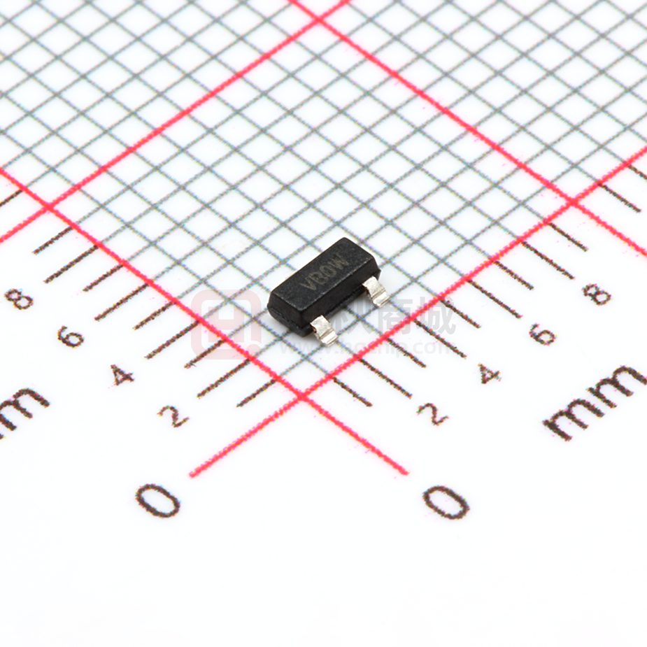
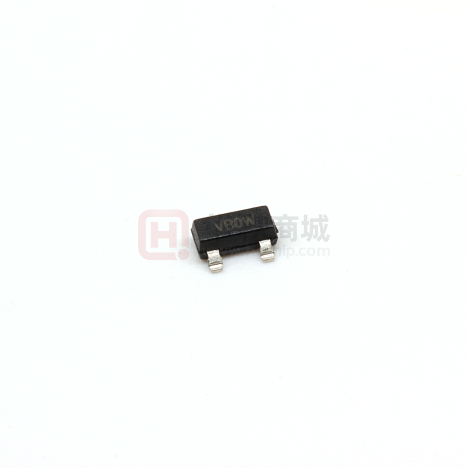
3-Lead SOT-23-3
Example:
XXNN
Device
I-Temp
Code
MCP1525
VANN
MCP1541
VBNN
Note:
Legend: XX...X
Y
YY
WW
NNN
e3
*
Note:
VA25
Applies to 3-Lead SOT-23.
Customer-specific information
Year code (last digit of calendar year)
Year code (last 2 digits of calendar year)
Week code (week of January 1 is week ‘01’)
Alphanumeric traceability code
Pb-free JEDEC designator for Matte Tin (Sn)
This package is Pb-free. The Pb-free JEDEC designator ( e3 )
can be found on the outer packaging for this package.
In the event the full Microchip part number cannot be marked on one line, it will
be carried over to the next line, thus limiting the number of available
characters for customer-specific information.
2001-2012 Microchip Technology Inc.
DS21653C-page 11
�21653C.book Page 12 Thursday, January 10, 2013 12:55 PM
MCP1525/41
3-Lead Plastic Transistor Outline (TO) (TO-92)
Note:
For the most current package drawings, please see the Microchip Packaging Specification located
at http://www.microchip.com/packaging
E1
D
n
1
L
1
2
3
B
p
c
A
R
Units
Dimension Limits
n
p
MIN
INCHES*
NOM
MAX
MILLIMETERS
NOM
3
1.27
3.30
3.62
4.45
4.71
4.32
4.64
2.16
2.29
12.70
14.10
0.36
0.43
0.41
0.48
4
5
2
3
MIN
Number of Pins
3
Pitch
.050
Bottom to Package Flat
A
.130
.143
.155
Overall Width
E1
.175
.186
.195
Overall Length
D
.170
.183
.195
Molded Package Radius
R
.085
.090
.095
Tip to Seating Plane
L
.500
.555
.610
c
Lead Thickness
.014
.017
.020
Lead Width
B
.016
.019
.022
Mold Draft Angle Top
4
5
6
Mold Draft Angle Bottom
2
3
4
*Controlling Parameter
Notes:
Dimensions D and E1 do not include mold flash or protrusions. Mold flash or protrusions shall not exceed
.010” (0.254mm) per side.
JEDEC Equivalent: TO-92
Drawing No. C04-101
DS21653C-page 12
MAX
3.94
4.95
4.95
2.41
15.49
0.51
0.56
6
4
2001-2012 Microchip Technology Inc.
�21653C.book Page 13 Thursday, January 10, 2013 12:55 PM
MCP1525/41
3-Lead Plastic Small Outline Transistor (TT) (SOT23)
Note:
For the most current package drawings, please see the Microchip Packaging Specification located
at http://www.microchip.com/packaging
E
E1
2
B
p1
n
D
p
1
c
A
A2
A1
L
Units
Dimension Limits
n
p
Number of Pins
Pitch
Outside lead pitch (basic)
Overall Height
Molded Package Thickness
Standoff §
Overall Width
Molded Package Width
Overall Length
Foot Length
Foot Angle
Lead Thickness
Lead Width
Mold Draft Angle Top
Mold Draft Angle Bottom
* Controlling Parameter
§ Significant Characteristic
MIN
p1
A
A2
A1
E
E1
D
L
c
B
.035
.035
.000
.083
.047
.110
.014
0
.004
.015
0
0
INCHES*
NOM
3
.038
.076
.040
.037
.002
.093
.051
.115
.018
5
.006
.017
5
5
MAX
.044
.040
.004
.104
.055
.120
.022
10
.007
.020
10
10
MILLIMETERS
NOM
3
0.96
1.92
0.89
1.01
0.88
0.95
0.01
0.06
2.10
2.37
1.20
1.30
2.80
2.92
0.35
0.45
0
5
0.09
0.14
0.37
0.44
0
5
0
5
MIN
MAX
1.12
1.02
0.10
2.64
1.40
3.04
0.55
10
0.18
0.51
10
10
Notes:
Dimensions D and E1 do not include mold flash or protrusions. Mold flash or protrusions shall not exceed
.010” (0.254mm) per side.
JEDEC Equivalent: TO-236
Drawing No. C04-104
2001-2012 Microchip Technology Inc.
DS21653C-page 13
�21653C.book Page 14 Thursday, January 10, 2013 12:55 PM
MCP1525/41
NOTES:
DS21653C-page 14
2001-2012 Microchip Technology Inc.
�21653C.book Page 15 Thursday, January 10, 2013 12:55 PM
MCP1525/41
APPENDIX A:
REVISION HISTORY
Revision C (December 2012)
Added a note to each package outline drawing.
Revision B (February 2005)
The following is the list of modifications:
1.
2.
3.
4.
5.
6.
Added bandwidth and capacitor specifications
(Section 1.0 “Electrical Characteristics”).
Moved Section 1.1 “Specification Descriptions and Test Circuits” to the specifications
section (Section 1.0 “Electrical Characteristics”).
Corrected plots in Section 2.0 “Typical Performance Curves”.
Added Section 3.0 “Pin Descriptions”.
Corrected package markings in
Section 5.0 “Packaging Information”.
Added Appendix A: “Revision History”.
Revision A (July 2001)
• Original Release of this Document.
2001-2012 Microchip Technology Inc.
DS21653C-page 15
�21653C.book Page 16 Thursday, January 10, 2013 12:55 PM
MCP1525/41
NOTES:
DS21653C-page 16
2001-2012 Microchip Technology Inc.
�21653C.book Page 17 Thursday, January 10, 2013 12:55 PM
MCP1525/41
PRODUCT IDENTIFICATION SYSTEM
To order or obtain information, e.g., on pricing or delivery, refer to the factory or the listed sales office.
PART NO.
X
/XX
Device
Temperature
Range
Package
Device
Temperature Range
Package
MCP1525:
MCP1541:
I
=
= 2.5V Voltage Reference
= 4.096 Voltage Reference
Examples:
a)
MCP1525T-I/TT:
Tape and Reel,
Industrial Temperature,
SOT23 package.
b)
MCP1525-I/TO:
Industrial Temperature,
TO-92 package.
c)
MCP1541T-I/TT:
Tape and Reel,
Industrial Temperature,
SOT23 package.
d)
MCP1541-I/TO:
Industrial Temperature,
TO-92 package.
-40C to +85C
TO = TO-92, Plastic Transistor Outline, 3-Lead
TT = SOT23, Plastic Small Outline Transistor, 3-Lead
2001-2012 Microchip Technology Inc.
DS21653C-page 17
�21653C.book Page 18 Thursday, January 10, 2013 12:55 PM
MCP1525/41
NOTES:
DS21653C-page 18
2001-2012 Microchip Technology Inc.
�21653C.book Page 19 Thursday, January 10, 2013 12:55 PM
Note the following details of the code protection feature on Microchip devices:
•
Microchip products meet the specification contained in their particular Microchip Data Sheet.
•
Microchip believes that its family of products is one of the most secure families of its kind on the market today, when used in the
intended manner and under normal conditions.
•
There are dishonest and possibly illegal methods used to breach the code protection feature. All of these methods, to our
knowledge, require using the Microchip products in a manner outside the operating specifications contained in Microchip’s Data
Sheets. Most likely, the person doing so is engaged in theft of intellectual property.
•
Microchip is willing to work with the customer who is concerned about the integrity of their code.
•
Neither Microchip nor any other semiconductor manufacturer can guarantee the security of their code. Code protection does not
mean that we are guaranteeing the product as “unbreakable.”
Code protection is constantly evolving. We at Microchip are committed to continuously improving the code protection features of our
products. Attempts to break Microchip’s code protection feature may be a violation of the Digital Millennium Copyright Act. If such acts
allow unauthorized access to your software or other copyrighted work, you may have a right to sue for relief under that Act.
Information contained in this publication regarding device
applications and the like is provided only for your convenience
and may be superseded by updates. It is your responsibility to
ensure that your application meets with your specifications.
MICROCHIP MAKES NO REPRESENTATIONS OR
WARRANTIES OF ANY KIND WHETHER EXPRESS OR
IMPLIED, WRITTEN OR ORAL, STATUTORY OR
OTHERWISE, RELATED TO THE INFORMATION,
INCLUDING BUT NOT LIMITED TO ITS CONDITION,
QUALITY, PERFORMANCE, MERCHANTABILITY OR
FITNESS FOR PURPOSE. Microchip disclaims all liability
arising from this information and its use. Use of Microchip
devices in life support and/or safety applications is entirely at
the buyer’s risk, and the buyer agrees to defend, indemnify and
hold harmless Microchip from any and all damages, claims,
suits, or expenses resulting from such use. No licenses are
conveyed, implicitly or otherwise, under any Microchip
intellectual property rights.
Trademarks
The Microchip name and logo, the Microchip logo, dsPIC,
FlashFlex, KEELOQ, KEELOQ logo, MPLAB, PIC, PICmicro,
PICSTART, PIC32 logo, rfPIC, SST, SST Logo, SuperFlash
and UNI/O are registered trademarks of Microchip Technology
Incorporated in the U.S.A. and other countries.
FilterLab, Hampshire, HI-TECH C, Linear Active Thermistor,
MTP, SEEVAL and The Embedded Control Solutions
Company are registered trademarks of Microchip Technology
Incorporated in the U.S.A.
Silicon Storage Technology is a registered trademark of
Microchip Technology Inc. in other countries.
Analog-for-the-Digital Age, Application Maestro, BodyCom,
chipKIT, chipKIT logo, CodeGuard, dsPICDEM,
dsPICDEM.net, dsPICworks, dsSPEAK, ECAN,
ECONOMONITOR, FanSense, HI-TIDE, In-Circuit Serial
Programming, ICSP, Mindi, MiWi, MPASM, MPF, MPLAB
Certified logo, MPLIB, MPLINK, mTouch, Omniscient Code
Generation, PICC, PICC-18, PICDEM, PICDEM.net, PICkit,
PICtail, REAL ICE, rfLAB, Select Mode, SQI, Serial Quad I/O,
Total Endurance, TSHARC, UniWinDriver, WiperLock, ZENA
and Z-Scale are trademarks of Microchip Technology
Incorporated in the U.S.A. and other countries.
SQTP is a service mark of Microchip Technology Incorporated
in the U.S.A.
GestIC and ULPP are registered trademarks of Microchip
Technology Germany II GmbH & Co. & KG, a subsidiary of
Microchip Technology Inc., in other countries.
All other trademarks mentioned herein are property of their
respective companies.
© 2001-2012, Microchip Technology Incorporated, Printed in
the U.S.A., All Rights Reserved.
Printed on recycled paper.
ISBN: 9781620768853
QUALITY MANAGEMENT SYSTEM
CERTIFIED BY DNV
== ISO/TS 16949 ==
2001-2012 Microchip Technology Inc.
Microchip received ISO/TS-16949:2009 certification for its worldwide
headquarters, design and wafer fabrication facilities in Chandler and
Tempe, Arizona; Gresham, Oregon and design centers in California
and India. The Company’s quality system processes and procedures
are for its PIC® MCUs and dsPIC® DSCs, KEELOQ® code hopping
devices, Serial EEPROMs, microperipherals, nonvolatile memory and
analog products. In addition, Microchip’s quality system for the design
and manufacture of development systems is ISO 9001:2000 certified.
DS21653C-page 19
�21653C.book Page 20 Thursday, January 10, 2013 12:55 PM
Worldwide Sales and Service
AMERICAS
ASIA/PACIFIC
ASIA/PACIFIC
EUROPE
Corporate Office
2355 West Chandler Blvd.
Chandler, AZ 85224-6199
Tel: 480-792-7200
Fax: 480-792-7277
Technical Support:
http://www.microchip.com/
support
Web Address:
www.microchip.com
Asia Pacific Office
Suites 3707-14, 37th Floor
Tower 6, The Gateway
Harbour City, Kowloon
Hong Kong
Tel: 852-2401-1200
Fax: 852-2401-3431
India - Bangalore
Tel: 91-80-3090-4444
Fax: 91-80-3090-4123
India - New Delhi
Tel: 91-11-4160-8631
Fax: 91-11-4160-8632
Austria - Wels
Tel: 43-7242-2244-39
Fax: 43-7242-2244-393
Denmark - Copenhagen
Tel: 45-4450-2828
Fax: 45-4485-2829
India - Pune
Tel: 91-20-2566-1512
Fax: 91-20-2566-1513
France - Paris
Tel: 33-1-69-53-63-20
Fax: 33-1-69-30-90-79
Japan - Osaka
Tel: 81-6-6152-7160
Fax: 81-6-6152-9310
Germany - Munich
Tel: 49-89-627-144-0
Fax: 49-89-627-144-44
Atlanta
Duluth, GA
Tel: 678-957-9614
Fax: 678-957-1455
Boston
Westborough, MA
Tel: 774-760-0087
Fax: 774-760-0088
Chicago
Itasca, IL
Tel: 630-285-0071
Fax: 630-285-0075
Cleveland
Independence, OH
Tel: 216-447-0464
Fax: 216-447-0643
Dallas
Addison, TX
Tel: 972-818-7423
Fax: 972-818-2924
Detroit
Farmington Hills, MI
Tel: 248-538-2250
Fax: 248-538-2260
Indianapolis
Noblesville, IN
Tel: 317-773-8323
Fax: 317-773-5453
Los Angeles
Mission Viejo, CA
Tel: 949-462-9523
Fax: 949-462-9608
Santa Clara
Santa Clara, CA
Tel: 408-961-6444
Fax: 408-961-6445
Toronto
Mississauga, Ontario,
Canada
Tel: 905-673-0699
Fax: 905-673-6509
Australia - Sydney
Tel: 61-2-9868-6733
Fax: 61-2-9868-6755
China - Beijing
Tel: 86-10-8569-7000
Fax: 86-10-8528-2104
China - Chengdu
Tel: 86-28-8665-5511
Fax: 86-28-8665-7889
China - Chongqing
Tel: 86-23-8980-9588
Fax: 86-23-8980-9500
Netherlands - Drunen
Tel: 31-416-690399
Fax: 31-416-690340
Korea - Daegu
Tel: 82-53-744-4301
Fax: 82-53-744-4302
Spain - Madrid
Tel: 34-91-708-08-90
Fax: 34-91-708-08-91
China - Hangzhou
Tel: 86-571-2819-3187
Fax: 86-571-2819-3189
Korea - Seoul
Tel: 82-2-554-7200
Fax: 82-2-558-5932 or
82-2-558-5934
China - Hong Kong SAR
Tel: 852-2943-5100
Fax: 852-2401-3431
Malaysia - Kuala Lumpur
Tel: 60-3-6201-9857
Fax: 60-3-6201-9859
China - Nanjing
Tel: 86-25-8473-2460
Fax: 86-25-8473-2470
Malaysia - Penang
Tel: 60-4-227-8870
Fax: 60-4-227-4068
China - Qingdao
Tel: 86-532-8502-7355
Fax: 86-532-8502-7205
Philippines - Manila
Tel: 63-2-634-9065
Fax: 63-2-634-9069
China - Shanghai
Tel: 86-21-5407-5533
Fax: 86-21-5407-5066
Singapore
Tel: 65-6334-8870
Fax: 65-6334-8850
China - Shenyang
Tel: 86-24-2334-2829
Fax: 86-24-2334-2393
Taiwan - Hsin Chu
Tel: 886-3-5778-366
Fax: 886-3-5770-955
China - Shenzhen
Tel: 86-755-8864-2200
Fax: 86-755-8203-1760
Taiwan - Kaohsiung
Tel: 886-7-213-7828
Fax: 886-7-330-9305
China - Wuhan
Tel: 86-27-5980-5300
Fax: 86-27-5980-5118
Taiwan - Taipei
Tel: 886-2-2508-8600
Fax: 886-2-2508-0102
China - Xian
Tel: 86-29-8833-7252
Fax: 86-29-8833-7256
Thailand - Bangkok
Tel: 66-2-694-1351
Fax: 66-2-694-1350
UK - Wokingham
Tel: 44-118-921-5869
Fax: 44-118-921-5820
China - Xiamen
Tel: 86-592-2388138
Fax: 86-592-2388130
China - Zhuhai
Tel: 86-756-3210040
Fax: 86-756-3210049
DS21653C-page 20
Italy - Milan
Tel: 39-0331-742611
Fax: 39-0331-466781
Japan - Tokyo
Tel: 81-3-6880- 3770
Fax: 81-3-6880-3771
11/29/12
2001-2012 Microchip Technology Inc.
�


 工商网监
湘ICP备2023018690号
工商网监
湘ICP备2023018690号