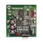
MCP1631HV
Multi-Chemistry
Battery Charger
Reference Design
© 2009 Microchip Technology Inc.
DS51791A
�Note the following details of the code protection feature on Microchip devices:
•
Microchip products meet the specification contained in their particular Microchip Data Sheet.
•
Microchip believes that its family of products is one of the most secure families of its kind on the market today, when used in the
intended manner and under normal conditions.
•
There are dishonest and possibly illegal methods used to breach the code protection feature. All of these methods, to our
knowledge, require using the Microchip products in a manner outside the operating specifications contained in Microchip’s Data
Sheets. Most likely, the person doing so is engaged in theft of intellectual property.
•
Microchip is willing to work with the customer who is concerned about the integrity of their code.
•
Neither Microchip nor any other semiconductor manufacturer can guarantee the security of their code. Code protection does not
mean that we are guaranteeing the product as “unbreakable.”
Code protection is constantly evolving. We at Microchip are committed to continuously improving the code protection features of our
products. Attempts to break Microchip’s code protection feature may be a violation of the Digital Millennium Copyright Act. If such acts
allow unauthorized access to your software or other copyrighted work, you may have a right to sue for relief under that Act.
Information contained in this publication regarding device
applications and the like is provided only for your convenience
and may be superseded by updates. It is your responsibility to
ensure that your application meets with your specifications.
MICROCHIP MAKES NO REPRESENTATIONS OR
WARRANTIES OF ANY KIND WHETHER EXPRESS OR
IMPLIED, WRITTEN OR ORAL, STATUTORY OR
OTHERWISE, RELATED TO THE INFORMATION,
INCLUDING BUT NOT LIMITED TO ITS CONDITION,
QUALITY, PERFORMANCE, MERCHANTABILITY OR
FITNESS FOR PURPOSE. Microchip disclaims all liability
arising from this information and its use. Use of Microchip
devices in life support and/or safety applications is entirely at
the buyer’s risk, and the buyer agrees to defend, indemnify and
hold harmless Microchip from any and all damages, claims,
suits, or expenses resulting from such use. No licenses are
conveyed, implicitly or otherwise, under any Microchip
intellectual property rights.
Trademarks
The Microchip name and logo, the Microchip logo, Accuron,
dsPIC, KEELOQ, KEELOQ logo, MPLAB, PIC, PICmicro,
PICSTART, rfPIC, SmartShunt and UNI/O are registered
trademarks of Microchip Technology Incorporated in the
U.S.A. and other countries.
FilterLab, Linear Active Thermistor, MXDEV, MXLAB,
SEEVAL, SmartSensor and The Embedded Control Solutions
Company are registered trademarks of Microchip Technology
Incorporated in the U.S.A.
Analog-for-the-Digital Age, Application Maestro, CodeGuard,
dsPICDEM, dsPICDEM.net, dsPICworks, dsSPEAK, ECAN,
ECONOMONITOR, FanSense, In-Circuit Serial
Programming, ICSP, ICEPIC, Mindi, MiWi, MPASM, MPLAB
Certified logo, MPLIB, MPLINK, mTouch, PICkit, PICDEM,
PICDEM.net, PICtail, PIC32 logo, PowerCal, PowerInfo,
PowerMate, PowerTool, REAL ICE, rfLAB, Select Mode, Total
Endurance, WiperLock and ZENA are trademarks of
Microchip Technology Incorporated in the U.S.A. and other
countries.
SQTP is a service mark of Microchip Technology Incorporated
in the U.S.A.
All other trademarks mentioned herein are property of their
respective companies.
© 2009, Microchip Technology Incorporated, Printed in the
U.S.A., All Rights Reserved.
Printed on recycled paper.
Microchip received ISO/TS-16949:2002 certification for its worldwide
headquarters, design and wafer fabrication facilities in Chandler and
Tempe, Arizona; Gresham, Oregon and design centers in California
and India. The Company’s quality system processes and procedures
are for its PIC® MCUs and dsPIC® DSCs, KEELOQ® code hopping
devices, Serial EEPROMs, microperipherals, nonvolatile memory and
analog products. In addition, Microchip’s quality system for the design
and manufacture of development systems is ISO 9001:2000 certified.
DS51791A-page ii
© 2009 Microchip Technology Inc.
�MCP1631HV MULTI-CHEMISTRY
BATTERY CHARGER
REFERENCE DESIGN
Table of Contents
Preface ........................................................................................................................... 1
Introduction............................................................................................................ 1
Document Layout .................................................................................................. 1
Conventions Used in this Guide ............................................................................ 2
Recommended Reading........................................................................................ 3
The Microchip Web Site ........................................................................................ 3
Customer Support ................................................................................................. 3
Document Revision History ................................................................................... 3
Chapter 1. Product Overview
1.1 Introduction ..................................................................................................... 5
1.2 What is the MCP1631HV Multi-Chemistry Battery Charger
Reference Design? ................................................................................... 6
1.3 What the MCP1631HV Multi-Chemistry Battery Charger
Reference Design kit includes .................................................................. 6
Chapter 2. Installation and Operation
2.1 Introduction ..................................................................................................... 7
2.2 Features ......................................................................................................... 7
2.3 Getting Started ............................................................................................... 7
Appendix A. Schematic and Layout
A.1 Introduction .................................................................................................. 13
A.2 Board – Schematic ....................................................................................... 14
A.3 Board – Top Silk Layer ................................................................................ 15
A.4 Board – Bottom Silk Layer ........................................................................... 16
A.5 Board – Top Metal Layer ............................................................................. 17
A.6 Board – Mid1 Metal Layer ............................................................................ 18
A.7 Board – Mid2 Metal Layer ............................................................................ 19
A.8 Board – Bottom Metal Layer ........................................................................ 20
Appendix B. Bill Of Materials (BOM)
Appendix C. Software
C.1 Device SOFTWARE Flowchart .................................................................... 23
C.2 Selected Software Constants and Definitions .............................................. 34
C.3 PIC16F883 Port Usage ................................................................................ 37
C.4 mikroElektronika’s mikroC™ Compiler Startup ............................................ 38
C.5 MPLAB® and PICkit™ 2 Debugging Exercise ............................................. 39
C.6 Lab Exercises .............................................................................................. 40
© 2009 Microchip Technology Inc.
DS51791A-page iii
�MCP1631HV Multi-Chemistry Battery Charger Reference Design
Appendix D. Design Example
D.1 Design Example ........................................................................................... 47
Worldwide Sales and Service .....................................................................................50
DS51791A-page iv
© 2009 Microchip Technology Inc.
�MCP1631HV MULTI-CHEMISTRY
BATTERY CHARGER
REFERENCE DESIGN
Preface
NOTICE TO CUSTOMERS
All documentation becomes dated, and this manual is no exception. Microchip tools and
documentation are constantly evolving to meet customer needs, so some actual dialogs
and/or tool descriptions may differ from those in this document. Please refer to our web site
(www.microchip.com) to obtain the latest documentation available.
Documents are identified with a “DS” number. This number is located on the bottom of each
page, in front of the page number. The numbering convention for the DS number is
“DSXXXXXA”, where “XXXXX” is the document number and “A” is the revision level of the
document.
For the most up-to-date information on development tools, see the MPLAB® IDE on-line help.
Select the Help menu, and then Topics to open a list of available on-line help files.
INTRODUCTION
This chapter contains general information that will be useful to know before using the
MCP1631HV Multi-Chemistry Battery Charger Reference Design. Items discussed in
this chapter include:
•
•
•
•
•
•
Document Layout
Conventions Used in this Guide
Recommended Reading
The Microchip Web Site
Customer Support
Document Revision History
DOCUMENT LAYOUT
This document describes how to use the MCP1631HV Multi-Chemistry Battery
Charger Reference Design. The manual layout is as follows:
• Chapter 1. “Product Overview” – Important information about the MCP1631HV
Multi-Chemistry Battery Charger Reference Design.
• Chapter 2. “Installation and Operation” – Includes instructions on how to get
started with this user’s guide and a description of the user’s guide.
• Appendix A. “Schematic and Layout” – Shows the schematic and layout
diagrams for the MCP1631HV Multi-Chemistry Battery Charger Reference
Design.
• Appendix B. “Bill Of Materials (BOM)” – Lists the parts used to build the
MCP1631HV Multi-Chemistry Battery Charger Reference Design.
• Appendix C. “Software” – Provides information about the application firmware
and where the source code can be found.
• Appendix D. “Design Example” – Shows a design example.
© 2009 Microchip Technology Inc.
DS51791A-page 1
�MCP1631HV Multi-Chemistry Battery Charger Reference Design
CONVENTIONS USED IN THIS GUIDE
This manual uses the following documentation conventions:
DOCUMENTATION CONVENTIONS
Description
Arial font:
Italic characters
Initial caps
Quotes
Underlined, italic text with
right angle bracket
Bold characters
‘bnnnn
Text in angle brackets < >
Courier font:
Plain Courier
Italic Courier
0xnnnn
Square brackets [ ]
Curly brackets and pipe
character: { | }
Ellipses...
DS51791A-page 2
Represents
Examples
Referenced books
Emphasized text
A window
A dialog
A menu selection
A field name in a window or
dialog
A menu path
MPLAB® IDE User’s Guide
...is the only compiler...
the Output window
the Settings dialog
select Enable Programmer
“Save project before build”
A dialog button
A tab
A binary number where n is a
digit
A key on the keyboard
Click OK
Click the Power tab
‘b00100, ‘b10
File>Save
Press ,
Sample source code
Filenames
File paths
Keywords
Command-line options
Bit values
A variable argument
#define START
autoexec.bat
c:\mcc18\h
_asm, _endasm, static
-Opa+, -Opa0, 1
file.o, where file can be
any valid filename
A hexadecimal number where 0xFFFF, 0x007A
n is a hexadecimal digit
Optional arguments
mcc18 [options] file
[options]
Choice of mutually exclusive errorlevel {0|1}
arguments; an OR selection
Replaces repeated text
var_name [,
var_name...]
Represents code supplied by void main (void)
user
{ ...
}
© 2009 Microchip Technology Inc.
�Preface
RECOMMENDED READING
This user's guide describes how to use MCP1631HV Multi-Chemistry Battery Charger
Reference Design. The following Microchip documents are available on our web site
(www.microchip.com) and recommended as supplemental reference resources.
MCP1631 Data Sheet, "High-Speed, Microcontroller-Adaptable, Pulse Width
Modulator", DS22063A
This data sheet provides detailed information regarding the MCP1631/MCP1631V,
MCP1631HV and MCP1631VHV product family.
PIC16F883 Data Sheet, "8-Pin Flash-Based, 8-Bit CMOS Microcontrollers with
Nano Watt Technology”, DS41291D
This data sheet provides detailed information regarding the PIC16F883 product family.
AN1137 Application Note, “Using the MCP1631 Family to Develop Low-Cost
Battery Chargers”, DS01137A
THE MICROCHIP WEB SITE
Microchip provides online support via our web site at www.microchip.com. This web
site is used as a means to make files and information easily available to customers.
Accessible by using your favorite Internet browser, the web site contains the following
information:
• Product Support – Data sheets and errata, application notes and sample
programs, design resources, user’s guides and hardware support documents,
latest software releases and archived software
• General Technical Support – Frequently Asked Questions (FAQs), technical
support requests, online discussion groups, Microchip consultant program
member listing
• Business of Microchip – Product selector and ordering guides, latest Microchip
press releases, listing of seminars and events, listings of Microchip sales offices,
distributors and factory representatives
CUSTOMER SUPPORT
Users of Microchip products can receive assistance through several channels:
•
•
•
•
•
Distributor or Representative
Local Sales Office
Field Application Engineer (FAE)
Technical Support
Development Systems Information Line
Customers should contact their distributor, representative or field application engineer
(FAE) for support. Local sales offices are also available to help customers. A listing of
sales offices and locations is included in the back of this document.
Technical support is available through the web site at: http://support.microchip.com
DOCUMENT REVISION HISTORY
Revision A (January 2009)
• Initial Release of this Document.
© 2009 Microchip Technology Inc.
DS51791A-page 3
�MCP1631HV Multi-Chemistry Battery Charger Reference Design
NOTES:
DS51791A-page 4
© 2009 Microchip Technology Inc.
�MCP1631HV MULTI-CHEMISTRY
BATTERY CHARGER
REFERENCE DESIGN
Chapter 1. Product Overview
1.1
INTRODUCTION
The MCP1631HV Multi-Chemistry reference design board is used to charge one to five
NiMH or NiCd batteries, charge one or two cell Li-Ion batteries, or drive one or two 1W
LEDs. The board uses the MCP1631HV high speed analog PWM and PIC16F883 to
generate the charge algorithm for NiMH, NiCd or Li-Ion batteries.
The MCP1631HV Multi-Chemistry Battery Charger is used to evaluate Microchip’s
MCP1631HV in a SEPIC power converter application. As provided, the MCP1631HV
Multi-Chemistry Battery Charger is user programmable using on board push buttons.
The board can charge NiMH, NiCd or Li-Ion batteries. The MCP1631HV Multi-Chemistry Battery Charger provides a constant current charge (Ni-based chemistry) and constant current / constant voltage (Li-Ion) with preconditioning, cell temperature
monitoring (Ni-based) and battery pack fault monitoring. Also, the charger provides a
status or fault indication. The MCP1631HV Multi-Chemistry Battery Charger automatically detects the insertion or removal of a battery pack.
This chapter covers the following topics.
• What is the MCP1631HV Multi-Chemistry Battery Charger Reference Design?
• What the MCP1631HV Multi-Chemistry Battery Charger Reference Design Kit
includes.
5.3V to 18V
Power Supply
B+
MCP1631HV SEPIC
THERM
Battery Charger
FIGURE 1-1:
Block Diagram.
© 2009 Microchip Technology Inc.
B-
Multi-Chemistry
+
MCP1631HV Multi-Chemistry Battery Charger Reference Design
DS51791A- page 5
�MCP1631HV Multi-Chemistry Battery Charger Reference Design
1.2
WHAT IS THE MCP1631HV MULTI-CHEMISTRY BATTERY CHARGER
REFERENCE DESIGN?
The MCP1631HV Multi-Chemistry Battery Charger is a complete stand-alone battery
charger for NiMH, NiCd or Li-Ion battery packs. The board may also be used to drive
LED devices using constant current mode. When charging NiMH or NiCd batteries the
reference design is capable of charging one to five batteries connected in series. If
Li-Ion chemistry is selected, the board is capable of charging one or two series
batteries. When the LED driver is selected, the board is capable of driving one to two
1W LEDs. This board utilizes Microchip’s MCP1631HV (high-speed PWM and
PIC16F883 MCU). The input voltage range for the demo board is 5.3V to 16V.
The board is capable of both boosting and bucking the input voltage in order to obtain
the desired output voltage because a SEPIC converter topology is used. The overvoltage limit for the board is set to 9V. The powertrain components may be changed to
allow for higher output voltages and power.
TABLE 1-1:
MULTI-CHEMISTRY CHARGER CAPABILITY
Battery Chemistry
Li-Ion
NiMH or NiCd
LED Driver
1 Cell
2 Cell
3 Cell
4 Cell
5 Cell
2A
1A
NA
NA
NA
1.5A
1.5A
1.5A
1.5A
1.5A
300 mA
300 mA
NA
NA
NA
An input terminal block is provided to apply the input voltage to the charger. An output
header is also provided as a means to connect the external battery pack or simulated
battery load and external 10K thermistor. A programming header is available for
updating the firmware contained in the PIC16F883.
1.3
WHAT THE MCP1631HV MULTI-CHEMISTRY BATTERY CHARGER
REFERENCE DESIGN KIT INCLUDES
This MCP1631HV Multi-Chemistry Battery Charger Reference Design kit includes:
• The MCP1631HV Multi-Chemistry Battery Charger Board,102-00232
• Analog and Interface Products Demonstration Boards CD-ROM includes
(DS21912):
- MCP1631HV Multi-Chemistry Battery Charger User’s Guide, (DS51697).
- MCP1631 Data Sheet, “High-Speed, Microcontroller-Adaptable, Pulse Width
Modulator”, (DS22063).
- PIC16F883 Data Sheet, “8-Pin Flash-Based, 8-Bit CMOS Microcontrollers
with nanoWatt Technology”, (DS41291).
- Application Note AN1137, “Using the MCP1631 Family to Develop Low-Cost
Battery Chargers”, (DS01137).
DS51791A- page 6
© 2009 Microchip Technology Inc.
�MCP1631HV MULTI-CHEMISTRY
BATTERY CHARGER
REFERENCE DESIGN
Chapter 2. Installation and Operation
2.1
INTRODUCTION
The MCP1631HV Multi-Chemistry Battery Charger demonstrates Microchip’s
high-speed Pulse Width Modulator (PWM), MCP1631HV, used in a multi-chemistry
battery charger application. When used in conjunction with a microcontroller, the
MCP1631HV will control the power system duty cycle to provide output voltage or
current regulation. The PIC16F883 microcontroller can be used to regulate output
voltage or set current, switching frequency and maximum duty cycle. The MCP1631HV
generates the duty cycle and provides fast overcurrent protection based upon various
external inputs. External signals include the switching frequency oscillator, the
reference voltage, the feedback voltage and the current sense. The output signal is a
square-wave pulse. The power train used for the MCP1631HV Multi-Chemistry Battery
Charger is a Single-Ended Primary Inductive Converter (SEPIC). The MCP1631HV
microcontroller is programmable, allowing the user to modify or develop their own
firmware routines to further evaluate the MCP1631HV Multi-Chemistry Battery Charger
in this application.
2.2
FEATURES
The MCP1631HV Multi-Chemistry Battery Charger has the following features:
•
•
•
•
•
•
•
•
•
•
•
Input Operating Voltage Range - +5.3V to +16V
Maximum of 2A Charge Current for single cell Li-Ion
Charge NiMH, NiCd or Li-Ion Chemistries
Charge 1 cell or 2 cell Li-Ion Batteries in Series
Charge 1 cell to 5 cell NiMH or NiCd Batteries in Series
Drive one or two 1 Watt LEDs in series.
Select Chemistry and Cells using push-buttons
ON/OFF switch
Charge Status Indication
Programmable Charge Profile
Programmable Overvoltage Shutdown (1.8V/Cell for NiMH/NiCd or 4.4V/Cell for
Li-Ion)
• Complete “C” source code is provided
2.3
GETTING STARTED
The MCP1631HV Multi-Chemistry Battery Charger is fully assembled and tested for
charging one or two series Li-Ion Batteries, one to five series cell NiMH or NiCd
batteries, or driving one to two 1 Watt LEDs. The charge termination for Li-Ion is based
upon a percentage of fast charge current, the charge termination for NiMH is based on
a negative voltage change versus time or positive temperature change versus time.
This board requires the use of an external voltage source to charge the series
connected batteries with a range of +5.3V to +16V input. An external load and
thermistor is also required to evaluate the charger reference design.
© 2009 Microchip Technology Inc.
DS51791A-page 7
�MCP1631HV Multi-Chemistry Battery Charger Reference Design
1 Cell 3,600 mA-hr Li-Ion Battery
Battery Voltage (V)
Charge Current (A)
5.0
4.0
3.0
2.0
1.0
180
165
150
135
120
105
90
75
60
45
30
15
0
0.0
Time (Minutes)
FIGURE 2-1:
Li-Ion.
MCP1631HV Multi-Chemistry Battery Charger Charge Profile,
3 Cell 2,000 mA-hr NiMH Batteries
60
40
3.0
30
2.0
20
150
135
120
105
90
75
60
0
45
0.0
30
10
15
1.0
Temperature (°C)
50
4.0
0
Battery Voltage (V)
Charge Current (A)
5.0
Time (Minutes)
FIGURE 2-2:
NiMH/NiCd.
DS51791A-page 8
MCP1631HV Multi-Chemistry Battery Charger Charge Profile,
© 2009 Microchip Technology Inc.
�Installation and Operation
2.3.1
Power Input and Output Connection
2.3.1.1
POWERING THE MCP1631HV MULTI-CHEMISTRY BATTERY
CHARGER
1. Apply the input voltage to the input terminal block, J1. The input voltage source
should be limited to the 0V to +16V range. For nominal operation the input
voltage should be between +5.3V and +16V.
2. Connect the positive side of the input source (+) to pin 1 of J1. Connect the negative or return side (-) of the input source to pin 2 of J1. Refer to Figure 2-3 below.
+12V
+Battery
GND
+Thermistor
-Battery,
-Thermistor
Programming
Header
Serial PICkit™
2 Header
FIGURE 2-3:
2.3.1.2
Setup Configuration Diagram.
APPLYING A LOAD TO THE MCP1631HV MULTI-CHEMISTRY
BATTERY CHARGER
1. To apply a load (battery pack), to the MCP1631HV Multi-Chemistry Battery
Charger, the positive side of the battery pack (B+) should be connected to pin 1
of J2. The negative side of the load (B-) should be connected to pin 5 of J2.
2. For NiMH or NiCd battery packs, a thermistor referenced to (B-) in the battery
pack should be utilized. EPCOS Inc. PN B57500M0103A005 is the recommended thermistor. If a thermistor is not available or not desired, a 10 kΩ resistor
should be placed between pins 4 and 5 of the battery header (J2) or charger will
detect a missing thermistor and no charge cycle will begin.
© 2009 Microchip Technology Inc.
DS51791A-page 9
�MCP1631HV Multi-Chemistry Battery Charger Reference Design
VBAT+
+
-
1,000 µF
10V Al
2Ω
10W
+
Variable
Power Supply
- 0V - 6V
VBAT–
FIGURE 2-4:
2.3.1.3
Simulated Battery Load.
SELECTING BATTERY CHEMISTRY AND NUMBER OF CELLS
• Three push buttons are used to start a charge cycle, select chemistry and select
number of series cells. There are two LEDs, (red - NiMH, green - Li-Ion, red +
green - LED Driver) used to indicate chemistry type and four yellow LEDs to
indicate the number of series cells selected (D6, D7, D8, D9).
• S1 (ON/OFF) is used to start and stop the charge cycle or to enter the programming mode. When the input voltage is within the specified operating range (+5.3V
to +16V), press and hold the ON/OFF button for 5 seconds, all LEDs with the
exception of D3 should be illuminated. Release S1 and STATUS LED (D3) will be
flashing, indicating that the board is in programming mode.
• Press S2 (CHEM) to select the desired chemistry, indication is provided by red
LED D4 (Li-Ion) or green LED D5 (NiMH/NiCd) or both (LED Driver).
• Press S3 (CELLS) to select the number of series cells, indication is provided by
yellow LEDs D6 thru D9 where D6 = bit 0 and D9 = bit 3 of a 4-bit hexadecimal
value.
• Once the desired chemistry and number of cells is selected, press S1 (ON/OFF)
to store the settings. The selected chemistry LED and number of series cells LED
both should be illuminated.
• To start a charge cycle press and release S1. D3 (green) will be illuminated
indicating a charge cycle has begun, the selected chemistry LED should flash
slowly indicating normal charge cycle conditions.
• If the chemistry LED is not flashing and the Status LED is flashing, a fault
condition has persisted for 5 attempts indicating that the charge cycle has
terminated.
• Remove input voltage and check connections and verify the proper battery pack
chemistry and number of series cells.
• Once the problem is corrected, apply the input voltage, verify chemistry and # of
cells LEDs and press S1 to start a charge cycle.
Note:
DS51791A-page 10
For single cell Li-Ion, a 3600 mA-Hr battery with internal protection circuitry
is recommended for evaluation. For NiMH charge cycle, Panasonic
HHR-210AA/B2B were used to develop the -dV/dt and +dT/dt termination
methods.
© 2009 Microchip Technology Inc.
�Installation and Operation
2.3.1.4
STATUS LED
The MCP1631HV Multi-Chemistry Battery Charger has an LED to indicate charge
status or fault status. Table 2-1 represents the state of the Status, Chemistry, and
Display LEDs during various states of the charge cycle.
TABLE 2-1:
Mode
LED INDICATOR TABLE
Status
Li-Ion
NiMH
LSBit 0
Bit 1
Bit 2
MSBit 3
Power-Up
OFF
CHEM
CHEM
#CELLS
#CELLS
#CELLS
#CELLS
Enter Config
OFF
ON
ON
ON
ON
ON
ON
Config
4Hz
CHEM
CHEM
#CELLS
#CELLS
#CELLS
#CELLS
Calibrated
4Hz
OFF
OFF
ON
ON
ON
ON
Off
OFF
CHEM
CHEM
#CELLS
#CELLS
#CELLS
#CELLS
Charging
#CELLS
#CELLS
#CELLS
#CELLS
FLASH
CHEM
CHEM
#CELLS
#CELLS
#CELLS
#CELLS
Fault-OV
2Hz
CHEM
CHEM
#CELLS
#CELLS
#CELLS
#CELLS
Fault-OT
1Hz
CHEM
CHEM
#CELLS
#CELLS
#CELLS
#CELLS
Term. Code
No Change
(#CELLS pressed)
No Change
No Change
ΔV/Δt
ΔT/Δt
OVP
OTP
State Code
(CHEM pressed)
No Change
No Change
STATE LS
Bit 0
STATE Bit
1
STATE Bit
2
STATE MS
Bit 3
Fault
TABLE 2-2:
State Code
ON
1/2 Hz CHEM 1/2 Hz CHEM
No Change
WHEN ‘CHEM’ SWITCH IS PRESSED, SHOWS CURRENT STATE
LSBit 0
Bit 1
Bit 2
MSBit 3
Startup
1
0
0
0
ON
0
1
0
0
Qualification
1
1
0
0
NiMH CC
0
0
1
0
NiMH Topoff
1
0
1
0
Li-Ion CC
0
1
1
0
Li-Ion CV
1
1
1
0
LED CC
0
0
0
1
Overvoltage
1
0
0
1
Off
0
1
0
1
© 2009 Microchip Technology Inc.
DS51791A-page 11
�MCP1631HV Multi-Chemistry Battery Charger Reference Design
2.3.1.5
CHARGE PROFILE
• Li-Ion
- Qualification: Precharge at 200 mA for VCELL < 3.0V
- Constant Current = 2A for 1 Cell, 1A for 2 Cell
- Constant Voltage = 4.20V, User Calibrated
- Charge Termination = 140 mA for 1 Cell and 2 Cell
- Overvoltage Detection, once detected, attempt to restart charge cycle 5 times,
if overvoltage is persistent, terminate attempts and flash STATUS LED.
• NiMH/NiCd
- Qualification: Precharge at 200 mA for VCELL < 0.9V.
- Constant Current = 1.5A for 1 to 5 Cells.
- Terminate Fast Charge for -dV/dT or +dT/dt.
- Timed 50 mA top off charge for 1 hour.
- Overvoltage Detection, once detected, will attempt to restart charge cycle five
times. If overvoltage is still present, charging will terminate and STATUS LED
will flash.
• LED Driver
- Constant Current = 0 to 300 mA for 1 to 2 LEDs.
- Pressing CHEM switch increments output current. Limited to 300 mA.
- Pressing CELLS switch decrements output current. Limited to 0 mA.
- Overvoltage Detection, once detected, will attempt to restart charge cycle five
times. If overvoltage is still present, charging will terminate and STATUS LED
will flash.
2.3.1.6
PROGRAMMING
Header J3 is provided for in-system circuit programming using either ICD 2 or
PICkit™ 2.
2.3.1.7
DATA LOGGING
Header J5 is provided for serial data logging using the PICkit™ Serial Analyzer. The
source code for the evaluation board contains the code necessary to transmit data via
a PICkit™ Serial interface to a PC running the PICkit Serial Analyzer GUI interface. The
data currently logged consists of charging current setpoint, output voltage, temperature
thermistor voltage, current system state, and termination code.
The data logging feature allows the user to create and save a complete charging profile
for a specific battery pack. The interface software provided with the PICkit Serial
Analyzer allows the user to save the logged data to a file.
DS51791A-page 12
© 2009 Microchip Technology Inc.
�MCP1631HV MULTI-CHEMISTRY
BATTERY CHARGER
REFERENCE DESIGN
Appendix A. Schematic and Layout
A.1
INTRODUCTION
This appendix contains the following schematics and layouts for the MCP1631
Multi-Chemistry Battery Charger Reference Design:
•
•
•
•
•
•
•
Board – Schematic
Board – Top Silk Layer
Board – Bottom Silk Layer
Board – Top Metal Layer
Board – Mid1 Metal Layer
Board – Mid2 Metal Layer
Board – Bottom Metal Layer
© 2009 Microchip Technology Inc.
DS51791A-page 13
�MCP1631HV Multi-Chemistry Battery Charger Reference Design
BOARD – SCHEMATIC
1
2
3
A.2
28
27
26
25
24
23
22
21
20
19
18
17
16
15
1
2
3
4
5
6
7
8
9
10
11
12
13
14
4
5
6
7
8
2
1
3
DS51791A-page 14
© 2009 Microchip Technology Inc.
�Schematic and Layout
A.3
BOARD – TOP SILK LAYER
© 2009 Microchip Technology Inc.
DS51791A-page 15
�MCP1631HV Multi-Chemistry Battery Charger Reference Design
A.4
BOARD – BOTTOM SILK LAYER
DS51791A-page 16
© 2009 Microchip Technology Inc.
�Schematic and Layout
A.5
BOARD – TOP METAL LAYER
© 2009 Microchip Technology Inc.
DS51791A-page 17
�MCP1631HV Multi-Chemistry Battery Charger Reference Design
A.6
BOARD – MID1 METAL LAYER
DS51791A-page 18
© 2009 Microchip Technology Inc.
�Schematic and Layout
A.7
BOARD – MID2 METAL LAYER
© 2009 Microchip Technology Inc.
DS51791A-page 19
�MCP1631HV Multi-Chemistry Battery Charger Reference Design
A.8
BOARD – BOTTOM METAL LAYER
DS51791A-page 20
© 2009 Microchip Technology Inc.
�MCP1631HV MULTI-CHEMISTRY
BATTERY CHARGER
REFERENCE DESIGN
Appendix B. Bill Of Materials (BOM)
TABLE B-1:
Qty
BILL OF MATERIALS (BOM)
Reference
Description
Manufacturer
Part Number
4
B1, B2, B3, B4
BUMPON HEMISPHERE
.44X.20 CLEAR
3M
SJ-5303 (CLEAR)
3
C1, C2, C4
CAP CERAMIC 10UF 25V X5R
1206
Panasonic® - ECG
ECJ-3YB1E106M
2
C11, C14
CAP 22PF 50V CERM CHIP
0805 SMD
Panasonic - ECG
ECJ-2VC1H220J
2
C15, C20
CAP 1500PF 50V CERM CHIP
0805
Panasonic - ECG
ECJ-2VB1H152K
2
C18, C19
CAP CER 4.7UF 10V X7R 20%
0805
TDK Corporation
C2012X7R1A475M
1
C3
CAP CER 2.2UF 25V X7R 0805 Murata Electronics®
North America
GRM21BR71E225KA73
L
8
C5, C7, C8, C9,
C12, C13, C16,
C17
CAP CER 1.0UF 25V X7R 0805 Taiyo Yuden
TMK212BJ105KG-TR
1
C6
CAP .1UF 16V CERAMIC X7R
0805
Panasonic - ECG
ECJ-2VB1C104K
2
D1, D4
LED 0805 Super RED Clear
Para Light Corp.
L-C170KRCT-U1
1
D2
DIODE SCHOTTKY 30V 3A
SMA
Diodes Inc.
B330A-13-F
2
D3, D5
LED 0805 Super Green Clear
Para Light Corp.
L-C170KGCT-U1
4
D6, D7, D8, D9
LED 0805 Super Yellow Clear
Para Light Corp.
L-C170KYCT-U1
1
J1
CONN TERM BLOCK 2.54MM
2POS
Phoenix Contact
1725656
1
J2
CONN HEADER 5POS .100
VERT TIN FRICTION LOCK
Molex® Electronics
22-23-2051
1
J3
CONN HEADER 5POS .100
VERT TIN
Molex Electronics
22-03-2051
1
J4
CONN HEADER 3POS .100
VERT TIN
Molex Electronics
22-23-2031
1/6
J5
CONN HEADER .100 SNGL
R/A 36POS
3M
929835-01-36-RK
1
JP1
BARE WIRE, 22 AWG to 26
AWG, 0.330
—
1
L1
INDUCT/XFRMR SHIELD DL
10UH SMD
1
PCB
RoHS Compliant Bare PCB,
MCP1631 Multi-Chemistry
Charger with Buck-Boost
Note 1:
Wurth Elektronik
—
—
744870100
104-00232
The components listed in this Bill of Materials are representative of the PCB assembly. The released BOM
used in manufacturing uses all RoHS-compliant components.
© 2009 Microchip Technology Inc.
DS51791A-page 21
�MCP1631HV Multi-Chemistry Battery Charger Reference Design
TABLE B-1:
Qty
BILL OF MATERIALS (BOM) (CONTINUED)
Reference
Description
Manufacturer
Part Number
1
Q1
HEX/MOS N-CHAN 30V 8.3A
8SOIC
International Rectifier
IRF7807VTRPBF
1
Q2
MOSFET N-CH 60V 280MA
SOT-23
Fairchild Semiconductor®
NDS7002A
3
R1, R10, R11
RES 1.00K OHM 1/8W 1% 0805 Panasonic - ECG
SMD
ERJ-6ENF1001V
1
R12
RES 301K OHM 1/8W 1% 0805 Panasonic - ECG
SMD
ERJ-6ENF3013V
1
R15
RES 10.0 OHM 1/8W 1% 0805
SMD
Panasonic - ECG
ERJ-6ENF10R0V
1
R17
RES 100K OHM 1/8W 1% 0805 Panasonic - ECG
SMD
ERJ-6ENF1003V
1
R18
RES 3.92K OHM 1/8W 1% 0805 Panasonic - ECG
SMD
ERJ-6ENF3921V
2
R2, R19
RES 10.0K OHM 1/8W 1% 0805 Panasonic - ECG
SMD
ERJ-6ENF1002V
2
R23, R35
RES 20.0K OHM 1/8W 1% 0805 Panasonic - ECG
SMD
ERJ-6ENF2002V
7
R25, R26, R27
R28, R29, R30
R31
RES 499 OHM 1/8W 1% 0805
SMD
Panasonic - ECG
ERJ-6ENF4990V
6
R3, R4, R5, R16, RES 49.9K OHM 1/8W 1% 0805 Panasonic - ECG
R21, R22
SMD
ERJ-6ENF4992V
1
R33
RES 5.60K OHM 1/8W 1% 0805 Panasonic - ECG
SMD
ERJ-6ENF5601V
2
R34, R24
RES 40.2K OHM 1/8W 1% 0805 Panasonic - ECG
SMD
ERJ-6ENF4022V
4
R6, R7, R13, R14 RES .22 OHM 1/4W 1% 1206
SMD
1
Panasonic - ECG
ERJ-8RQFR22V
R8
RES 39.2K OHM 1/8W 1% 0805 Panasonic - ECG
SMD
ERJ-6ENF3922V
1
R9
RES 348K OHM 1/8W 1% 0805 Panasonic - ECG
SMD
ERJ-6ENF3483V
3
S1, S2, S3
SWITCH TACT 6MM 260GF
SMT
E-Switch
TL3301NF260QG
4
TP11-TP14
SMT Testpoint
Keystone Electronics®
5016
1
U1
MCP1631HV 5.0V 20 Pin
TSSOP High Speed PWM
Microchip Technology Inc.
MCP1631HV-500E/ST
1
U2
IC PIC MCU FLASH 4KX14
28SSOP
Microchip Technology Inc.
PIC16F883-I/SS
Note 1:
The components listed in this Bill of Materials are representative of the PCB assembly. The released BOM
used in manufacturing uses all RoHS-compliant components.
DS51791A-page 22
© 2009 Microchip Technology Inc.
�MCP1631HV MULTI-CHEMISTRY
BATTERY CHARGER
REFERENCE DESIGN
Appendix C. Software
C.1
DEVICE SOFTWARE FLOWCHART
For the latest copy of the MCP1631HV Multi-Chemistry Battery Charger Reference
Design firmware, visit our web site at www.microchip.com.
C.1.1
Software Functions
C.1.1.1
INTERRUPT()
Interrupt ()
Timer 1?
Update LED's
Update One Second flag
Clear Timer 0 Interrupt Flag
Y
Y
Reload PWM Timer
High/Low Count
+
Clear Timer 1 Interrupt
Flag
Timer 0?
Ret
© 2009 Microchip Technology Inc.
DS51791A-page 23
�MCP1631HV Multi-Chemistry Battery Charger Reference Design
C.1.1.2
MAIN()
Main ()
Initialize Processor
Initialize Parameters
Read
A/D?
Y
ON /
OFF?
Y
Second?
Y
SampleADC()
CheckModeChange()
DoOneSecondTasks()
Update LED's
C.1.1.3
SAMPLEADC()
SampleADC()
Running_Sum +=
ReadADCChannel()
N
Samples?
Y
Average Samples and Store
Select Next A/D Channel
Ret
DS51791A-page 24
© 2009 Microchip Technology Inc.
�Software
C.1.1.4
READADCCHANNEL()
ReadADCChannel()
Select Channel MUX
Delay 5 µs
Start Conversion
Complete?
N
Return Result
C.1.1.5
CHECKMODECHANGE()
CheckModeChange()
Y
On/Off
Pressed?
Config?
Y
Y
ON?
Hold for 5 seconds to enter Config Mode
Setup()
State = Startup
Initialize parameters
SetParameters()
Ret
© 2009 Microchip Technology Inc.
DS51791A-page 25
�MCP1631HV Multi-Chemistry Battery Charger Reference Design
C.1.1.6
SETPARAMETERS()
SetParameters()
NiMH/NiCd
Li-Ion
Chemistry?
LED Driver
Setup LED Parameters
Setup NiMH Parameters
Setup Li-Ion Parameters
Ret
C.1.1.7
SETIREF()
SetIRef(IRef)
IRef = 0?
N
Limit IRef to Min/Max Boundaries
Pause PWM Timer 1
Shutdown Timer 1
Ref Current = 0
Setup Timer 1 Reload Variables
Re-enable PW Timer 1
Ret
DS51791A-page 26
© 2009 Microchip Technology Inc.
�Software
C.1.1.8
SETUP()
Setup()
N
ON/OFF_SW?
Y
CHEM_SW?
CELLS_SW?
Next Chemistry
Y
Calibrate?
Y
Increment Number
of Cells
Li-Ion Calibration
Apply 4.2V Reference
To Battery Connector
Turn On 4 DISPLAY and
2 CHEM LED's
Average 16 A/D Battery
Voltage Readings
Store Average in EEPROM
Y
CELLS_SW?
A
C.1.1.9
B
INCREMENTIREF()
IncrementIRef(int inc)
N
inc = 0?
SetIRef
(IRef + inc)
Ret
© 2009 Microchip Technology Inc.
DS51791A-page 27
�MCP1631HV Multi-Chemistry Battery Charger Reference Design
C.1.1.10 DOONESECONDTASKS()
DoOneSecondTasks()
Decrement
Charge Timer
Update Chemistry LED's
OverVoltage?
Y
State = OV
A
DoOneSecondTasks()
A
Y
OT?
OT Count
= 0?
Y
State = OFF
Cause = OTP
Decrement OT Count
B
DS51791A-page 28
C
© 2009 Microchip Technology Inc.
�Software
DoOneSecondTasks()
B
OPEN
THERMISTOR?
Reload OT Count
Y
OT Count
= 0?
Y
State = OFF
Cause = OPEN_T
Decrement OT Count
(NiMH or MiCD compilations only)
C
C
DoOneSecondTasks()
STARTUP
Charge
Timer
= 0?
Y
State = ON
Charge Timer = Charge Timeout
Switch (State)
SHDN = 0
OTCount = OTP Retries
SetIRef()
D
© 2009 Microchip Technology Inc.
DS51791A-page 29
�MCP1631HV Multi-Chemistry Battery Charger Reference Design
DoOneSecondTasks()
D
ON
Switch (State)
Cause = 0
SHDN = 1
Reference Current MAX = Condition Current
Reference Current MIN = 2
SetIRef(ConditionCurrent)
State = QUALIFICATION
STATUS LED = ON
E
DoOneSecondTasks()
E
QUALIFICATION
VBAT
>=
Condition
Voltage?
Y
Initialize
Variables
Li-Ion?
Y
Switch (State)
N
IRefMax
<
Condition
Current?
Y
SetIRef(ChargeCurrent)
SetIRef(Initial)
State = LI_CC
NiMH?
Y
N
State = LED_CC
State = NM_CC
F
DS51791A-page 30
© 2009 Microchip Technology Inc.
�Software
DoOneSecondTasks()
F
NM_CC
Switch (State)
IncrementIRef()
Update Peak Voltage
Check for V/ t
Check for
T/ t
Check Termination Flags
Cause =
V/ t
Cause =
T/ t
State = NM_TOPOFF
Last Bat = Bat
Last Temp = Temp
Check For Charge Timer Timeout
State = OFF
G
G
NM_TOPOFF
Charge
Timer
= 0?
Switch (State)
Y
State = OFF
Status LED = OFF
H
© 2009 Microchip Technology Inc.
DS51791A-page 31
�MCP1631HV Multi-Chemistry Battery Charger Reference Design
DoOneSecondTasks()
H
LI_CC
Battery
<
Charge
Voltage
?
Y
IncrementIREF()
Switch (State)
State = LI_CV
IRefMin = ChargeTermination
Y
Charge
Timer
= 0?
State = OFF
I
DoOneSecondTasks()
I
LI_CV
Battery
>=
Charge
Voltage
?
Y
IncrementIRef(-Value)
Switch (State)
IRef
<
Termination
?
Charge
Timer
= 0?
Y State = OFF
Status LED = OFF
Y
State = OFF
J
DS51791A-page 32
© 2009 Microchip Technology Inc.
�Software
DoOneSecondTasks()
J
LED_CC
CHEM SW
?
Y
IncrementIRef(+Value)
Switch (State)
CELLS SW
?
Y
IncrementIRef(-Value)
Reset Over Voltage Retry
K
DoOneSecondTasks()
K
OV
SHDN = 0
SetIRef(0)
ChargeTimer = 2 seconds
Switch (State)
OV Count
= 0?
Y
State = OFF
Cause = OVP
Decrement OV Count
State = STARTUP
L
© 2009 Microchip Technology Inc.
DS51791A-page 33
�MCP1631HV Multi-Chemistry Battery Charger Reference Design
DoOneSecondTasks()
L
OFF
SHDN = 0
SetIRef(0)
Switch (State)
Ret
C.2
SELECTED SOFTWARE CONSTANTS AND DEFINITIONS
1. FOSC_KHZ = 8000
Microprocessor Oscillator Frequency in kHz.
2. CHARGER_SYSTEM = BUCK_BOOST_REF_DESIGN_BOARD
Selects charger system option to build. Multiple options can be created which
each use a single header file containing parameters for that specific system.
Options for CHARGER_SYSTEM are:
MULTICHEMISTRY_REF_DESIGN_BOARD_102_00232
3. DVDT_TERMINATION = ENABLED
Used to mask NiMH termination caused by battery voltage DV/Dt. When
DISABLED, allows the user to create complete charge profile by ignoring battery
voltage termination.
4. DTDT_TERMINATION = ENABLED
Used to mask NiMH termination caused by battery temperature DT/Dt. When
DISABLED, allows the user to create complete charge profile by ignoring battery
temperature termination. Termination due to battery overtemperature is always
enabled.
5. LION_SUPPORT = ENABLED
Enables support for Lithium Ion batteries.
6. NIMH_SUPPORT = ENABLED
Enable support for Nickel Metal Hydride batteries.
7. R24 = ((float)(39.6))
Voltage reference resistor divider highside resistor value (divider at PIC port C1).
8. R34 = ((float)(39.6))
Voltage reference resistor divider lowside resistor value (divider at PIC port C1).
9. MCP1631_ISIN_AMPLIFICATION = 10.0
MCP1631HV ISin Current Sense Input amplification.
10. R6 ((float)(0.22)) = Current Sense (ISin) Resistor
11. R7 ((float)(0.22)) = Current Sense (ISin) Resistor
DS51791A-page 34
© 2009 Microchip Technology Inc.
�Software
12. MCP1631_VSIN_RES_DIVIDER_VOLTAGE_SENSE = ((float)((100.0 + 301.0)
/(100.0 + 301.0 + 348.0)))
MCP1631 Voltage Sense (VSin) Resistor Divider (0.53538).
13. BATTERY_MV_PER_BIT = ((float)(ADC_MV_PER_BIT/
MCP1631_VSIN_RES_DIVIDER_VOLTAGE_SENSE))
Battery voltage A/D value in millivolts per bit.
14. LI_ION_OVER_VOLTAGE_CHARGE = ((int)(200.0/BATTERY_MV_PER_BIT))
Cell overvoltage charge in mV (not averaged) = 50 mV to 200 mV.
15. LI_ION_CONDITION_CURRENT = ((int)(200.0/BATTERY_MA_PER_BIT))
Cell conditioning current in mA (0.2°C)
16. LI_ION_CONDITION_VOLTAGE = ((int)(3000.0/BATTERY_MV_PER_BIT))
Cell conditioning voltage in mV. Below this value is preconditioning area.
17. LI_ION_CHARGE_CURRENT = ((int)(1200.0/BATTERY_MA_PER_BIT))
Constant Current mode charging current in mA (0.5°C to 1°C).
18. LI_ION_CHARGE_TERMINATION_CURRENT =
((int)(84.0/BATTERY_MA_PER_BIT))
Charge termination current in mA (0.07°C).
19. NIMH_NICD_OVER_VOLTAGE_CHARGE = ((int)(1800.0/
BATTERY_MV_PER_BIT))
Cell overvoltage charge in mV (not averaged).
20. NIMH_NICD_CONDITION_CURRENT = ((int)(140.0/
BATTERY_MA_PER_BIT))
Cell conditioning current in mA (0.2°C to 0.3°C).
21. NIMH_NICD_CONDITION_VOLTAGE = ((int)(900.0 /
BATTERY_MV_PER_BIT))
Cell conditioning voltage in mV. Below this value is preconditioning area.
22. NIMH_NICD_CHARGE_CURRENT = ((int)(700.0 / BATTERY_MA_PER_BIT))
Constant Current mode charging current in mA (0.5°C to 1°C).
23. NIMH_NICD_CHARGE_TERMINATION_CURRENT = ((int)(35.0 /
BATTERY_MA_PER_BIT))
Charge termination current in mA (0.033°C to 0.05°C).
24. NIMH_NICD_CHARGE_TOPOFF_TIME = (60 * 60)
Charge Topoff Time in seconds during Charge Termination mode.
25. NIMH_NICD_CHARGE_OVTEMP_SETPOINT =
((float)(THERMISTOR_OHMS_45C))
Overtemperature Shutdown limit. Set to Thermistor ohms at desired shutdown
temperature limit.
26. NIMH_NICD_CHARGE_DTDT_60SEC_THRESHOLD = ((int)((0.3 +
THERMISTOR_DEG_C_PER_BIT/2.0)/ THERMISTOR_DEG_C_PER_BIT))
Normal termination temperature change threshold in degrees Celsius over a 60
second span. (0.3 to 0.5 dending on charge rate).
27. CHARGE_DVDT_PEAK_DETECT_COUNT = 3
Sets termination based upon number of sequencial 60 second battery voltage
samples which have been lower than peak reading value.
28. VSOUT_NOISE_LEVEL_IN_MV = ((float) 3.0)
Noise level at VSOUT input to the A/D converter in mV. Approximately 3 - 5 mV
of noise. Used to offset readings.
29. DVDT_MV_PER_CELL = ((float) 6.0 )
Termination due to change in voltage per cell in millivolts over a 60 second
interval. Termination Deadband for battery voltage dropoff after peak detect.
© 2009 Microchip Technology Inc.
DS51791A-page 35
�MCP1631HV Multi-Chemistry Battery Charger Reference Design
30. EE_CHEMISTRY_DEFAULT = LiIon
Default Chemistry.
31. EE_NUMBER_OF_CELLS_DEFAULT = 2
Default number of cells value.
32. EE_LION_CAL_VOLTAGE_DEFAULT = ((int)((float)(4200.00 /
BATTERY_MV_PER_BIT)))
Default Lithium Ion battery calibration value.
33. EE_CHARGE_TIMEOUT_DEFAULT = (5*60*60)
Maximum charging time.
NiMH = Use (C rating in mAh/Charge Current) + 1hr Topoff + 0.25hr pre-condition)
*60 sec * 60 min
Lithium Ion = Use about 2.5 * (C rating in mAh/Charge Current) * 60 sec * 60 min
34. OSCILLATOR_DUTY_CYCLE = 25
Oscillator duty cycle in percent. Must be in 1/16th intervals due to 4 bit counter.
35. RS232_DATALOGGING = ENABLED
Set to ENABLE for logging data out to USART port and PICkitTM Serial Analyzer.
Set to DISABLED to remove logging code.
36. THERMISTOR_SUPPORT = ENABLED
Set to ENABLE for thermistor support. Used for NiMH and NiCD charging.
Set to DISABLED to remove thermistor code.
37. LED_DRIVER_SUPPORT = ENABLED
Set to ENABLE for LED driver support.
Set to DISABLED to remove LED driver code.
38. LED_DRIVER_OVER_VOLTAGE = ((int)(3600.0 / BATTERY_MV_PER_BIT))
Set this value to the voltage in mV that is the absolute limit of each single LED.
The system will go into overvoltage shutdown mode if the output voltage exceeds
this value times the number of LED series connected cells being driven.
39. LED_DRIVER_CONDITION_CURRENT =
((int)(10.0/BATTERY_MA_PER_BIT))
LED conditioning (startup) current.
40. LED_DRIVER_CONDITION_VOLTAGE = ((int)(0.0/ BATTERY_MV_PER_BIT))
LED conditioning voltage is 0 volts. No conditioning required.
41. LED_DRIVER_CURRENT = ((int)(300.0 / BATTERY_MA_PER_BIT))
LED Driver current maximum value. This is the upper current limit value that the
driver will deliver to the LED output.
42. LED_DRIVER_OVTEMP_SETPOINT = ((float)(THERMISTOR_OHMS_45C))
Optional LED overtemperature limit may be used to limit LED temperature.
Set LED_DRIVER_OVTEMP_SETPOINT to one of the Thermistor Ohms
definitions for the desired shutdown temperature.
43. MAX_LED_CELLS = 2
Maximum number of 1W LED cells in series that will be driven by the driver
output.
DS51791A-page 36
© 2009 Microchip Technology Inc.
�Software
C.3
PIC16F883 PORT USAGE
/* Port A */
PORTA.0
ADC_THERMISTOR_TEMPERATURE: Thermistor A/D input
PORTA.1
ADC_BATTTERY_VOLTAGE: Battery Voltage A/D input
PORTA.4
SHDN: System Shutdown and Thermistor Supply Output
PORTA.5
ONOFF_SWITCH: On/Off’ switch input
PORTA.6
NUMCELLS_SWITCH: Number of Cells’ switch input
PORTA.7
CHEMISTRY_SWITCH: Chemistry’ switch input
/* Port B */
PORTB.0
LIION_LED: Li-Ion’ LED output
PORTB.1
NIMH_LED: NiMH’ LED output
PORTB.2
LED_1_CELL: LS Bit ‘0’ Hex LED display output
PORTB.3
LED_2_CELL: Bit ‘1’ LED Hex display output
PORTB.4
LED_3_CELL: Bit ‘2’ LED Hex display output
PORTB.5
LED_4_CELL: MS Bit ‘3’ LED Hex display output
PORTB.6
In-Circuit Serial Programming CLOCK Line
PORTB.7
In-Circuit Serial Programming DATA Line
/* Port C */
PORTC.1
PWM_CURRENT_REF_OUT: Current Reference PWM output to
MCP1631HV VREF input
PORTC.2
OSC_OUT: Oscillator PWM output to MCP1631HV OSCin input
PORTC.5
STATUS_LED: Status’ LED output
PORTC.6
USART Transmit port. PICkit™ Serial Analyzer interface.
PORTC.7
USART Receive port. PICkit Serial Analyzer interface.
© 2009 Microchip Technology Inc.
DS51791A-page 37
�MCP1631HV Multi-Chemistry Battery Charger Reference Design
C.4
mikroElektronika’s mikroC™ COMPILER STARTUP
1. Startup mikroC™ compiler (compiler not supplied, available at:
http://www.mikroe.com).
2. From the toolbar, select “Project | Open Project”.
3. Browse to the evaluation board source code path.
4. Select the existing project file, named
“MCP1631HVBuckBoostBatteryChargerReferenceDesign.ppc”.
5. From the toolbar, select : “Project | Edit Project”. The page contains Processor,
Clock, and Config settings.
6. From the toolbar, select: “Tools | Options”. The page contains the compiler
settings.
7. From the toolbar, select: “View | Code Explorer”. This will show/hide the Code
Explorer and Project Setup frames.
8. From the toolbar, select: “View | Messages”. This will show/hide the Message
frame at the bottom of the screen.
9. In the Project Setup Frame, click on the Project Summary tab. This shows the
files for the project.
10. From the toolbar, select: “Project | Build”. This will build the currently load project.
11. The compiler results will be displayed in the Message frame. Verify success.
DS51791A-page 38
© 2009 Microchip Technology Inc.
�Software
C.5
MPLAB® AND PICKIT™ 2 DEBUGGING EXERCISE
1.
2.
3.
4.
5.
6.
7.
8.
9.
10.
11.
12.
13.
14.
15.
16.
17.
18.
19.
20.
21.
22.
23.
Startup MPLAB (not supplied, available at: http://www.microchip.com).
From the toolbar, select “File | Open Workspace”.
Browse to the evaluation board source code path.
Select the existing workspace file named
“MCP1631HVBuckBoostBatteryChargerReferenceDesign.mcw” or create a new one.
Connect the PICkit 2 programmer to header J3 on the battery charger board.
Align Pin 1 of the header with the Pin 1 mark on the programmer.
Set the bench power supply voltage control to minimum voltage output.
Turn on the power supply and set the output voltage to 8V. Turn off the power
supply.
Connect the bench power supply to the battery charger board. Connect +V(8V)
to J1-1 and –V (Ground) to J1-2.
Turn on the power supply.
From the toolbar, select “Debugger | Connect”. The debugger should find the
PIC16F883 processor.
From the toolbar, select “File | Import”.
Browse to the source code path.
Select the existing project file named
“MCP1631HVBuckBoostBatteryChargerReferenceDesign.hex”.
From the toolbar, select “Debugger | Program”. The debugger will program the
PIC16F883 with the imported hex file.
From the toolbar, select “Debugger | Reset | Processor Reset”. This must always
be done after programming.
From the toolbar, select “File | Open”.
In the “Files of type” text box, select “List Files (*.lst)”.
Click on “MCP1631HVBuckBoostBatteryChargerReferenceDesign.lst”.
Click on “Open”. This opens the mikroC™ listing file for the project. Variable and
Code addresses are at the end.
Scroll to the end of the listing file and locate the code label “L_main_1:”. Write
down the function address.
In the “Program Memory” window, scroll down until you reach the same address
as the “L_main_1:” function address. Right click on the line and set a breakpoint.
From the toolbar, select “Debugger | Run”. The debugger will stop at the
breakpoint. Disable the breakpoint.
From the toolbar, select “Debugger | Run”. The debugger will continue.
When debugging the battery charger board, be careful when setting breakpoints. If the
breakpoint occurs while the Voltage Reference PWM is HIGH, the VREF voltage will rise
to about 2.5V. The MCP1631HV will then attempt to supply the current for the given
VREF, which will be high (about 2.5V / 1.1 = 2.27A). The current is limited by the VREF
signal which is in turn limited by the VREF voltage divider resistor pair R24 and R34.
© 2009 Microchip Technology Inc.
DS51791A-page 39
�MCP1631HV Multi-Chemistry Battery Charger Reference Design
C.6
LAB EXERCISES
1. Startup the mikroCTM compiler and load the
“MCP1631HVBuckBoostBatteryChargerReferenceDesign.ppc” if it does not
load up automatically.
2. Startup MPLAB and load the
“MCP1631HVBuckBoostBatteryChargerReferenceDesign.mcw” workspace if it
does not start up automatically.
C.6.1
Li-Ion Only Exercise (single cell, 1200 mAh pack)
1. In the mikroC™ “Project Summary” frame, click on the “H files” branch to expand
the ‘.H’ file list.
2. Double click on the
“MULTICHEMISTRY_REF_DESIGN_BOARD_102_00232.H” file to open it.
3. Scroll through the header file and locate “#define LION_SUPPORT”.
Set it to “ENABLED”.
4. Scroll through the header file and locate “#define NIMH_SUPPORT”.
Set it to “DISABLED”.
5. Scroll through the header file and locate “#define LED_DRIVER_SUPPORT”.
Set it to “DISABLED”.
6. Scroll down to the “#IF (LION_SUPPORT == ENABLED) section of the header
file. The section contains Lithium Ion specific parameters. Note that there is a
Nickel Metal Hydride and LED Driver section also.
7. Set the LI_ION_CONDITION_CURRENT to 200 mAh. (Conditioning mode
current)
8. Set the LI_ION_CONDITION_VOLTAGE to 3000 mV. (Transition point from
Conditioning to CC mode)
9. Set the LI_ION_CHARGE_CURRENT to 1200 mAh. (CC mode current)
10. Set the LI_ION_CHARGE_TERMINATION_CURRENT to 84 mAh. (0.07C –
Termination Current for CV mode)
11. Save the file (File | Save).
12. Compile (Project | Build).
13. Open MPLAB and load the workspace if it is not already loaded. (File | Open
Workspace) {Source
Directory}\MCP1631HVBuckBoostBatteryChargerReferenceDesign.mcw
14. Import the new “MCP1631HVBuckBoostBatteryChargerReferenceDesign.hex”
file. (File | Import)
15. Download the file (Debugger | Program) and reset the processor (Debugger |
Reset | Processor Reset).
16. Run the new program (Debugger | Run).
17. Calibrate the Li-Ion Termination Voltage.
18. Disconnect and turn on the power supply and set the variable output voltage to
4.200V. Turn off the power supply.
19. Connect the fixed 12V supply (+) lead to the input connector (+) pin J1-1.
20. Connect the fixed 12V supply (-) lead to the input connector (-) pin J1-2.
21. Connect the 4.200V variable supply (+) lead to the battery connector (+) pin J2-1.
22. Connect the 4.200V variable supply (-) lead to the battery connector (-) pin J2-5.
23. Turn on the power supply.
DS51791A-page 40
© 2009 Microchip Technology Inc.
�Software
24. Press and hold the “ON/OFF” button on the charger board until the LED’s flash
(about 5 seconds). The board is now in Configuration Mode.
25. Press and release the “CHEM” button until the “Li-Ion” LED is on.
26. Press and release the “# CELLS” button until the “0” display LED is on and the
“1,2,3” display LED’s are off.
27. Press and hold the “# CELLS” button on the charger board until the LED’s flash
(about 5 seconds). The board is now calibrated to use the 4.200V as the Li-Ion
battery voltage.
28. Press the “ON/OFF” button. The charger will exit Configuration mode.
29. Turn off and disconnect the power supply.
30. Reconnect the variable supply (+) lead to the input connector (+) pin J1-1.
31. Reconnect the variable supply (-) lead to the input connector (-) pin J1-2.
32. Connect the Li-Ion battery pack to the charger board J2 connector.
33. Turn on the supply and set the voltage to 8.0V (any voltage between 6V and 12V
is good).
34. Press the “ON/OFF” button. The charger will start charging the battery.
35. Press the “CHEM” button to display the current charger state in HEX. “0” LED is
the LS Bit.
36. Press the “# CELLS” button to display the termination cause. No LED means no
premature termination.
37. Using an oscilloscope, refer to A.2 “Board – Schematic” and A.3 “Board – Top
Silk Layer” and probe the following components:
- VREF = TP3
- PWM = TP4
- Oscillator = TP5
- VSOUT = TP6
- Slope Compensation = TP7
- Temperature = TP8 (if used)
- FB = TP9
- Drain Voltage = TP10
- Output Voltage = TP11
38. Press the “ON/OFF” button. The charger will stop charging the battery.
© 2009 Microchip Technology Inc.
DS51791A-page 41
�MCP1631HV Multi-Chemistry Battery Charger Reference Design
C.6.2
NiMH Lab Exercise (3 Cell, 700 mAh pack, with thermistor)
1. In the mikroC™ “Project Summary” frame, click on the “H files” branch to expand
the ‘.H’ file list.
2. Double click on the
“MULTICHEMISTRY_REF_DESIGN_BOARD_102_00232.H” file to open it.
3. Scroll through the header file and locate “#define LION_SUPPORT”.
Set it to “DISABLED”.
4. Scroll through the header file and locate “#define NIMH_SUPPORT”.
Set it to “ENABLED”.
5. Scroll through the header file and locate “#define LED_DRIVER_SUPPORT”.
Set it to “DISABLED”.
6. Scroll down to the “#IF (NIMH_SUPPORT == ENABLED) section of the header
file. The section contains Nickel Metal Hydride and NiCd specific parameters.
7. Set the NIMH_NICD_CONDITION_CURRENT to 140 mAh. (0.2C Conditioning
mode current)
8. Set the NIMH_NICD_CONDITION_VOLTAGE to 900 mV. (Transition point from
Conditioning to CC mode)
9. Set the NIMH_NICD_CHARGE_CURRENT to 700 mAh. (1.0C Constant Current
Charge)
10. Set the NIMH_NICD_CHARGE_TERMINATION_CURRENT to 84 mAh. (0.07C
– Termination Current for CV mode)
11. Set the DVDT_MV_PER_CELL to 6.0. (Termination Voltage change per cell per
minute in millivolts)
12. Set the NIMH_NICD_CHARGE_DTDT_60SEC_THRESHOLD to 0.3. (Termination Temperature change per minute in degrees Celsius)
13. Set the NIMH_NICD_CHARGE_OVTEMP_SETPOINT to
THERMISTOR_OHMS_45C. (Termination temperature for safety)
14. Save the file (File | Save).
15. Compile (Project | Build).
16. Open MPLAB and load the workspace if it is not already loaded. (File | Open
Workspace) MCP1631HVBuckBoostBatteryChargerReferenceDesign.mcw
17. Import the new “MCP1631HVBuckBoostBatteryChargerReferenceDesign.hex”
file. (File | Import)
18. Download the file (Debugger | Program) and reset the processor (Debugger |
Reset | Processor Reset).
19. Run the new program (Debugger | Run).
20. Turn on the power supply and set the output voltage to 8V. Turn off the power
supply.
21. Connect the variable 8V supply (+) lead to the input connector (+) pin J1-1.
22. Connect the variable 8V supply (-) lead to the input connector (-) pin J1-2.
23. Connect the NiMH battery pack to the charger board J2 connector.
24. Turn on the variable 8V supply.
25. Press and hold the “ON/OFF” button on the charger board until the LED’s flash
(about 5 seconds). The board is now in Configuration Mode.
26. Press and release the “CHEM” button until the “NiMH” LED is on.
DS51791A-page 42
© 2009 Microchip Technology Inc.
�Software
27. Press and release the “# CELLS” button until the “0” and “1” “Display” LED’s are
on and the “2” and “3” “Display” LED’s are off. The LED display now displays “3”
in Hexadecimal.
28. Press the “ON/OFF” button. The charger will exit Configuration mode.
29. Press the “ON/OFF” button. The charger will start charging the battery.
30. Press the “CHEM” button to display the current charger state in HEX. “0”
“Display” LED is LS Bit.
31. Press the “# CELLS” button to display the termination cause. No LED means no
premature termination.
32. Using an oscilloscope, refer to Appendices A.2 “Board – Schematic” and
A.3 “Board – Top Silk Layer” and probe the following components:
- VREF = TP3
- PWM = TP4
- Oscillator = TP5
- VSOUT = TP6
- Slope Compensation = TP7
- Temperature = TP8
- FB = TP9
- Drain Voltage = TP10
- Output Voltage = TP11
33. Press the “ON/OFF” button. The charger will stop charging the battery.
© 2009 Microchip Technology Inc.
DS51791A-page 43
�MCP1631HV Multi-Chemistry Battery Charger Reference Design
C.6.3
LED Driver Lab Exercise (Two 1 Watt LED’s in series)
1. In the mikroC™ “Project Summary” frame, click on the “H files” branch to expand
the ‘.H’ file list.
2. Double click on the
“MULTICHEMISTRY_REF_DESIGN_BOARD_102_00232.H” file to open it.
3. Scroll through the header file and locate “#define LION_SUPPORT”.
Set it to “DISABLED”.
4. Scroll through the header file and locate “#define NIMH_SUPPORT”.
Set it to “DISABLED”.
5. Scroll through the header file and locate “#define LED_DRIVER_SUPPORT”.
Set it to “ENABLED”.
6. Scroll down to the “#IF (LED_DRIVER_SUPPORT == ENABLED) section of the
header file. The section contains LED Driver specific parameters.
7. Set the LED_DRIVER_OVER_VOLTAGE to 3600 mV. (Overvoltage Shutdown
value per LED).
8. Set the LED_DRIVER_CONDITION_CURRENT to 10 mAh.
9. Set the LED_DRIVER_CONDITION_VOLTAGE to 0 mV. (Skips Conditioning
State, not needed).
10. Set the LED_DRIVER_CURRENT to 300 mAh. (Constant Current mode).
11. Save the file (File | Save).
12. Compile (Project | Build).
13. Open MPLAB and load the workspace if it is not already loaded. (File | Open
Workspace) MCP1631HVBuckBoostBatteryChargerReferenceDesign.mcw.
14. Import the new “MCP1631HVBuckBoostBatteryChargerReferenceDesign.hex”
file. (File | Import)
15. Download the file (Debugger | Program) and reset the processor (Debugger |
Reset | Processor Reset).
16. Run the new program (Debugger | Run).
17. Turn on the power supply and set the output voltage to 8V. Turn off the power
supply.
18. Connect the variable 8V supply (+) lead to the input connector (+) pin J1-1.
19. Connect the variable 8V supply (-) lead to the input connector (-) pin J1-2.
20. Connect the two 1 watt LED’s in series to the charger board J2 connector.
21. Turn on the variable 8V supply.
22. Press and hold the “ON/OFF” button on the charger board until the LED’s flash
(about 5 seconds). The board is now in Configuration Mode.
23. Press and release the “CHEM” button until both the “NiMH” and “LiIon” LEDs are
on.
24. Press and release the “# CELLS” button until the “1” “Display” LED is on and the
“0”, “2” and “3” “Display” LED’s are off. The LED display now displays “2” in
Hexadecimal.
25. Press the “ON/OFF” button. The charger will exit Configuration mode.
26. Press the “ON/OFF” button. The charger will start charging the battery.
27. Press the “CHEM” button to display the current charger state in HEX. “0”
“Display” LED is LS Bit.
28. Press the “# CELLS” button to display the termination cause. No LED means no
premature termination.
DS51791A-page 44
© 2009 Microchip Technology Inc.
�Software
29. Using an oscilloscope, refer to Appendices A.2 “Board – Schematic” and
A.3 “Board – Top Silk Layer” and probe the following components:
- VREF = TP3
- PWM = TP4
- Oscillator = TP5
- VSOUT = TP6
- Slope Compensation = TP7
- Temperature = TP8 (if used)
- FB = TP9
- Drain Voltage = TP10
- Output Voltage = TP11
30. Press the “ON/OFF” button. The charger will stop charging the battery.
© 2009 Microchip Technology Inc.
DS51791A-page 45
�MCP1631HV Multi-Chemistry Battery Charger Reference Design
NOTES:
DS51791A-page 46
© 2009 Microchip Technology Inc.
�MCP1631HV MULTI-CHEMISTRY
BATTERY CHARGER
REFERENCE DESIGN
Appendix D. Design Example
D.1
DESIGN EXAMPLE
D.1.1
•
•
•
•
•
•
•
•
•
•
Design Parameters:
POUT = 10W (typical)
VIN = 6V to 16V for MCP1631HV. Choose VIN = 6V for worst case (WC).
VOUT = 8.4V for two Li-Ion batteries or 6.6V for four NiMH batteries
IOUT = 1.5A for 4 NiMH batteries. Choose DIL = 20%, IOUT = 300 mA.
η = Switcher Efficiency @ 80% (typical)
VF = Schottky Diode Drop @ 0.35V (typical)
IIN_WC = IOUT * VOUT_WC /(VIN_WC * ç) = 1.5A * 6.6V/(6V * 0.8) = 2.06A
FOSC = 500 kHz, TSWITCH = 1/FSWITCH = 2 µs
DOSC = 25%, tOSC_ON = 0.5 µs, tOSC_OFF = 1.5 µs
Choose C20 (Artificial Ramp) = 1500 pF
D.1.2
Design:
• Duty Cycle (D) = ((VOUT + VF)/η)/(((VOUT + VF)/η) + VIN)
= ((8.4V + 0.35)/0.8)/(((8.4V + 0.35)/0.8) + 6V)
= 65% (worst case is two Li-Ion batteries)
• tON = D * 1/FSWITCH = 0.65/500 kHz = 1.3 µs
• tOFF = TSWITCH - tON = 2 µs – 1.3 µs = 0.7 µs
• L = VIN * D * TSWITCH/ΔIL = 6V * 0.65 * 2 µs/300 mA = 26 µH.
For SEPIC coupled inductor, use ½ L because VIN “sees” 2 inductors.
LCOUPLED = 26 µH/2 = 13 µH. Choose 10 µH as standard value.
• ΔIL = 2 * VIN * D * TSWITCH / (4 * LCOUPLED) = 2*6V*0.65*2 µs/(4*10 µH)
ΔIL ≅ 390 mA
• ΔIIN = ΔIL = 390 mA
• IIN = IOUT * VOUT/(VIN * η)= 1.5A * 6.6V/( 6V * 0.8) = 2.06A
IIN PEAK = IIN + ½ ΔIL = 2.06A + 0.195A = 2.26A
• POUT = VOUT * IOUT = 6.6V * 1.5A = 9.9W
D.1.3
Slope Compensation:
• MArtificial Ramp = ΔIL * RSENSE/tOSC_FF
= 390 mA * 0.11Ω/1.5 us = 0.0429V/1.5 µs
But the ramp divider is (R10 + R11)/(R10 + R11 + R35)
= (1k + 1k)/(1k + 1k + 20k) = 2k/22k = 1/11
= (0.0429V/1.5 µs)/(1/11) = 471.9 mV/1.5 µs
• τArtificial Ramp (R33 & C20) - Using VOUT = VIN (1-e-(T/τ))
= -tOFF/(Ln(1-(VOUT/VIN)))
= -1.5 µs/(Ln(1 – (0.4719V/5.0V)))
= -1.5 µs/Ln (0.90562) = 15.13 µs
© 2009 Microchip Technology Inc.
DS51791A-page 47
�Design Example
• RArtificial Ramp = τArtificial Ramp/CArtificial Ramp = 15.13 µs/1500 pF
= 10 kΩ (max), use around 5.6 kΩ to 9.1 kΩ for tolerances
An R value of 5.6 kΩ was used for the Eval Board.
D.1.4
Coupling Capacitor:
• SWON, D = 25%, t = 0.5 µs
IRIPPLE = tON * 2VIN/4L = 0.5 µs * (2)(6V)/(4*10 µH) = 0.150A
I1 = IOUT – ½ IRIPPLE = 1.5A – 0.075A = 1.425A
I2 = IOUT + ½ IRIPPLE = 1.5A + 0.075A = 1.575A
IRMS_ON = SQRT(D * (I12 + I1 * I2 + I22)/3) (for a trapezoidal waveform)
= SQRT(0.25 * (1.4252 + 1.425 * 1.575 + 1.5752)/3
= 0.750A
• SWOFF, D = 75%, t = 1.5 µs
IRIPPLE = tOFF * 2VIN/4L = 1.5 µs * (2)(6V)/(4*10 µH) = 0.450A
I1 = -IIN_WC – ½ IRIPPLE = -2.06A – 0.225A = -2.285A
I2 = -IIN_WC + ½ IRIPPLE = -2.06A + 0.225A = -1.835A
IRMS_OFF = SQRT(D * (I12 + I1 * I2 + I22)/3)
= SQRT(0.75 * [-2.2852 + (-2.285 * (-1.835)) + (-1.835)2]/3)
= 1.79A
- IRMS = SQRT (IRMS_ON2 + IRMS_OFF2)
= SQRT (0.7502 + 1.792)
= 1.94A
• Worst-Case Capacitor Current is 1.94A.
Choose a capacitor that is rated for at least the worst-case current.
© 2009 Microchip Technology Inc.
DS51791A-page 48
�Design Example
NOTES:
© 2009 Microchip Technology Inc.
DS51791A-page 49
�WORLDWIDE SALES AND SERVICE
AMERICAS
ASIA/PACIFIC
ASIA/PACIFIC
EUROPE
Corporate Office
2355 West Chandler Blvd.
Chandler, AZ 85224-6199
Tel: 480-792-7200
Fax: 480-792-7277
Technical Support:
http://support.microchip.com
Web Address:
www.microchip.com
Asia Pacific Office
Suites 3707-14, 37th Floor
Tower 6, The Gateway
Harbour City, Kowloon
Hong Kong
Tel: 852-2401-1200
Fax: 852-2401-3431
India - Bangalore
Tel: 91-80-3090-4444
Fax: 91-80-3090-4080
India - New Delhi
Tel: 91-11-4160-8631
Fax: 91-11-4160-8632
Austria - Wels
Tel: 43-7242-2244-39
Fax: 43-7242-2244-393
Denmark - Copenhagen
Tel: 45-4450-2828
Fax: 45-4485-2829
India - Pune
Tel: 91-20-2566-1512
Fax: 91-20-2566-1513
France - Paris
Tel: 33-1-69-53-63-20
Fax: 33-1-69-30-90-79
Japan - Yokohama
Tel: 81-45-471- 6166
Fax: 81-45-471-6122
Germany - Munich
Tel: 49-89-627-144-0
Fax: 49-89-627-144-44
Atlanta
Duluth, GA
Tel: 678-957-9614
Fax: 678-957-1455
Boston
Westborough, MA
Tel: 774-760-0087
Fax: 774-760-0088
Chicago
Itasca, IL
Tel: 630-285-0071
Fax: 630-285-0075
Dallas
Addison, TX
Tel: 972-818-7423
Fax: 972-818-2924
Detroit
Farmington Hills, MI
Tel: 248-538-2250
Fax: 248-538-2260
Kokomo
Kokomo, IN
Tel: 765-864-8360
Fax: 765-864-8387
Los Angeles
Mission Viejo, CA
Tel: 949-462-9523
Fax: 949-462-9608
Santa Clara
Santa Clara, CA
Tel: 408-961-6444
Fax: 408-961-6445
Toronto
Mississauga, Ontario,
Canada
Tel: 905-673-0699
Fax: 905-673-6509
Australia - Sydney
Tel: 61-2-9868-6733
Fax: 61-2-9868-6755
China - Beijing
Tel: 86-10-8528-2100
Fax: 86-10-8528-2104
China - Chengdu
Tel: 86-28-8665-5511
Fax: 86-28-8665-7889
Korea - Daegu
Tel: 82-53-744-4301
Fax: 82-53-744-4302
China - Hong Kong SAR
Tel: 852-2401-1200
Fax: 852-2401-3431
Korea - Seoul
Tel: 82-2-554-7200
Fax: 82-2-558-5932 or
82-2-558-5934
China - Nanjing
Tel: 86-25-8473-2460
Fax: 86-25-8473-2470
Malaysia - Kuala Lumpur
Tel: 60-3-6201-9857
Fax: 60-3-6201-9859
China - Qingdao
Tel: 86-532-8502-7355
Fax: 86-532-8502-7205
Malaysia - Penang
Tel: 60-4-227-8870
Fax: 60-4-227-4068
China - Shanghai
Tel: 86-21-5407-5533
Fax: 86-21-5407-5066
Philippines - Manila
Tel: 63-2-634-9065
Fax: 63-2-634-9069
China - Shenyang
Tel: 86-24-2334-2829
Fax: 86-24-2334-2393
Singapore
Tel: 65-6334-8870
Fax: 65-6334-8850
China - Shenzhen
Tel: 86-755-8203-2660
Fax: 86-755-8203-1760
Taiwan - Hsin Chu
Tel: 886-3-572-9526
Fax: 886-3-572-6459
China - Wuhan
Tel: 86-27-5980-5300
Fax: 86-27-5980-5118
Taiwan - Kaohsiung
Tel: 886-7-536-4818
Fax: 886-7-536-4803
China - Xiamen
Tel: 86-592-2388138
Fax: 86-592-2388130
Taiwan - Taipei
Tel: 886-2-2500-6610
Fax: 886-2-2508-0102
China - Xian
Tel: 86-29-8833-7252
Fax: 86-29-8833-7256
Thailand - Bangkok
Tel: 66-2-694-1351
Fax: 66-2-694-1350
Italy - Milan
Tel: 39-0331-742611
Fax: 39-0331-466781
Netherlands - Drunen
Tel: 31-416-690399
Fax: 31-416-690340
Spain - Madrid
Tel: 34-91-708-08-90
Fax: 34-91-708-08-91
UK - Wokingham
Tel: 44-118-921-5869
Fax: 44-118-921-5820
China - Zhuhai
Tel: 86-756-3210040
Fax: 86-756-3210049
01/16/09
DS51791A-page 50
© 2009 Microchip Technology Inc.
�