MCP2200
USB 2.0 to UART Protocol Converter with GPIO
Features
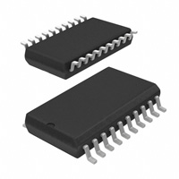
Package Types
Universal Serial Bus (USB)
The device is offered in the following packages:
• Supports Full-Speed USB (12 Mb/s)
• Implements USB Protocol Composite Device:
- Communication Device Class (CDC) for
Communications and Configuration
- Human Interface Device (HID) for I/O control
• 128-Byte Buffer to Handle Data Throughput at
Any UART Baud Rate:
- 64-byte transmit
- 64-byte receive
• Fully Configurable VID and PID Assignments and
String Descriptors
• Bus-Powered or Self-Powered
• USB 2.0 Compliant: TID 40001150
• 20-lead VQFN (5x5 mm)
• 20-lead SOIC
• 20-lead SSOP
Universal Asynchronous Receiver/Transmitter
(UART)
• Responds to SET_LINE_CODING Commands to
Dynamically Change Baud Rates
• Supports Baud Rates: 300-1000k
• Hardware Flow Control
• UART Signal Polarity Option
General Purpose Input/Output (GPIO) Pins
• Eight General Purpose I/O pins
EEPROM
• 256 Bytes of User EEPROM
Other
• USB Activity LED Outputs (TxLED and RxLED)
• SSPND Output Pin
• USBCFG Output Pin (indicates when the enumeration is completed)
• Operating Voltage: 3.0V-5.5V
• Oscillator Input: 12 MHz
• Electrostatic Discharge (ESD) Protection: >4 kV
Human Body Model (HBM)
• Industrial (I) Operating Temperature: –40°C to
+85°C
• Passes Automotive AEC-Q100 Reliability Testing
2010-2021 Microchip Technology Inc.
OSC1
VDD
VSS
D+
OSC2
20 19 18 17 16
9 10
11 GP2
Rx
CTS
6 7 8
Tx
GP5 4
GP4 5
15 D14 Vusb
13 GP0/SSPND
12 GP1/USBCFG
EP
21
GP6/RxLED 3
RTS
RST 1
GP7/TxLED 2
GP3
USB Driver and Software Support
• Uses Standard Windows® Drivers for Virtual Com
Port (VCP): Windows XP (SP2 or later), Windows
Vista, Windows 7, Windows 8, Windows 8.1 and
Windows 10
• Configuration Utility for Initial Configuration
MCP2200
5x5 VQFN*
MCP2200
SOIC, SSOP
VDD
OSC1
OSC2
RST
GP7/TxLED
GP6/RxLED
GP5
GP4
GP3
Tx
1
2
3
4
5
6
7
8
9
10
20
19
18
17
16
15
14
13
12
11
VSS
D+
DVusb
GP0/SSPND
GP1/USBCFG
GP2
CTS
Rx
RTS
* Includes Exposed Thermal Pad (EP); see Table 1-1.
DS20002228E-page 1
�MCP2200
Block Diagram
Configuration &
Control Registers
GP5
GP3
GP1
GP4
GP2
GP0
TxLED RxLED
GPIO
USB LEDs
256 Byte
EEPROM
Tx
Rx
D+
UART
Controller
USB Protocol
Controller
Control
CTS
USB
Transceiver
D-
RTS
Baud
Generator
VUSB
State USB
Clock Clock
DS20002228E-page 2
VSS
OSC
Reset
3.3V
LDO
VSS
OSC1 OSC2
RST
VDD
2010-2021 Microchip Technology Inc.
�MCP2200
1.0
FUNCTIONAL DESCRIPTION
The MCP2200 is a USB-to-UART serial converter that
enables USB connectivity in applications that have a
UART interface. The device reduces external components by integrating the USB termination resistors. The
MCP2200 also has 256 bytes of integrated user
EEPROM.
TABLE 1-1:
The MCP2200 has eight general purpose input/output
pins. Four pins have alternate functions to indicate
USB and communication status. See Table 1-1 and
Section 1.6 “GPIO Module” for details about the pin
functions.
PINOUT DESCRIPTION
Pin
Name
VQFN
SSOP, Pin
SOIC Type
GP0/SSPND
13
16
I/O
General purpose I/O
USB suspend status pin
(refer to Section 1.6.1.1 “SSPND
Pin Function”)
GP1/USBCFG
12
15
I/O
General purpose I/O
USB configuration status pin
(refer to Section 1.6.1.2 “USBCFG
Pin Function”)
GP2
11
14
I/O
General purpose I/O
GP3
6
9
I/O
General purpose I/O
Standard Function
Alternate Function
GP4
5
8
I/O
General purpose I/O
GP5
4
7
I/O
General purpose I/O
GP6/RxLED
3
6
I/O
General purpose I/O
USB receive activity LED output
(refer to Section 1.6.1.3 “RxLED
Pin Function (IN Message)”)
GP7/TxLED
2
5
I/O
General purpose I/O
USB transmit activity LED output
(refer to Section 1.6.1.4 “TxLED
Pin Function (OUT Message)”)
CTS
10
13
I
Hardware flow control “Clear to Send”
input signal
RTS
8
11
O
Hardware flow control “Request to Send”
output signal
Rx
9
12
I
USART RX input
Tx
7
10
O
USART TX output
RST
1
4
I
Reset input must be externally biased
VDD
18
1
P
Power
VSS
17
20
P
Ground
OSC1
19
2
I
Oscillator input
OSC2
20
3
O
Oscillator output
D+
16
19
I/O
USB D+
D-
15
18
I/O
USB D-
Vusb
14
17
P
USB power pin (internally connected to
3.3V). Should be locally bypassed with a
high-quality ceramic capacitor.
EP
21
—
—
Exposed Thermal Pad (EP). Do not
electrically connect.
2010-2021 Microchip Technology Inc.
DS20002228E-page 3
�MCP2200
1.1
Supported Operating Systems
Windows XP (SP2 and later), Windows Vista, Windows
7, Windows 8, Windows 8.1 and Windows 10 operating
systems are supported.
1.1.1
ENUMERATION
The MCP2200 will enumerate as a USB device after
Power-on Reset (POR). The device enumerates as
both a Human Interface Device (HID) for I/O control,
and a Virtual Com Port (VCP).
1.1.1.1
Human Interface Device (HID)
The MCP2200 enumerates as an HID, so the device
can be configured and the I/O can be controlled. A DLL
that facilitates I/O control through a custom interface is
supplied by Microchip.
1.1.1.2
Virtual Com Port (VCP)
The VCP enumeration implements the USB-to-UART
data translation.
1.2
Control Module
The control module is the heart of the MCP2200. All
other modules are tied together and controlled via the
control module. The control module manages the data
transfers between the USB and the UART, as well as
the command requests generated by the USB host
controller and the commands for controlling the
function of the UART and I/O.
1.2.1
SERIAL INTERFACE
The control module interfaces to the UART and USB
modules.
1.2.2
INTERFACING TO THE DEVICE
The MCP2200 can be accessed for reading and writing
via USB host commands. The device cannot be
accessed and controlled via the UART interface.
1.3
UART Interface
The MCP2200 UART interface consists of the Tx and
Rx data signals and the RTS/CTS flow control pins.
The UART is configurable for several baud rates. The
available baud rates are listed in Table 1-3.
DS20002228E-page 4
1.3.1
INITIAL CONFIGURATION
The default UART configuration is 19200, 8, N, 1. The
default start-up baud rate can be changed using the
Microchip-supplied configuration PC tool.
Alternatively, a custom configuration tool can be
created using the Microchip-supplied DLL to set the
baud rate as well as other parameters. See Section 2.0
“Configuration” for details.
TABLE 1-2:
UART CONFIGURATIONS
Parameter
Configuration
Primary Baud Rates
See Table 1-3
Data Bits
8
Parity
N
Stop Bits
1
1.3.2
GET/SET LINE CODING
The GET_LINE_CODING and SET_LINE_CODING
commands are used to read and set the UART
parameters while in operation. For example,
HyperTerminal sends the SET_LINE_COMMAND when
connecting to the port. The MCP2200 responds by
setting the baud rate only. The other parameters (data
bits, parity, stop bits) remain unchanged.
1.3.2.1
Rounding Errors
The primary baud rate setting (with the rounding errors)
is shown in Table 1-3. If baud rates other than the ones
shown in the table are used, the error percentage can
be calculated using Equation 1-1 to find the actual
baud rate.
TABLE 1-3:
UART PRIMARY BAUD
RATES
Desired Rate
Actual rate
% Error
300
300
0.00%
1200
1200
0.00%
2400
2400
0.00%
4800
4800
0.00%
9600
9600
0.00%
19200
19200
0.00%
38400
38339
0.16%
57600
57692
0.16%
115200
115385
0.16%
230400
230769
0.16%
460800
461538
0.16%
921600
923077
0.16%
2010-2021 Microchip Technology Inc.
�MCP2200
EQUATION 1-1:
SOLVING FOR ACTUAL
BAUD RATE
MHzActualRate = 12
-----------------int x
Where:
1.3.3
12 MHz x = -------------------------------Desired Baud
CUSTOM BAUD RATES
Custom baud rates are configured by sending the
SET_LINE_CODING USB command, or by using the
DLL. See Section 2.0 “Configuration” for more
information.
1.3.4
HARDWARE FLOW CONTROL
1.4
USB Protocol Controller
The USB controller in the MCP2200 is full-speed USB
2.0 compliant.
• Composite device (CDC + HID):
- CDC: USB-to-UART communications
- HID: I/O control, EEPROM access and initial
configuration
• 128-byte buffer to handle data throughput at any
UART baud rate:
- 64-byte transmit
- 64-byte receive
• Fully configurable VID and PID assignments and
descriptors (stored on-chip)
• Bus-powered or self-powered
Hardware flow control uses the RTS and CTS pins as
a handshake between two devices. The RTS pin of
one device is typically connected to the CTS of the
other device.
1.4.1
RTS is an active-low output that notifies the other
device when it is ready to receive data by driving the pin
low. The MCP2200 trip point for deasserting RTS (high)
is 63 characters. This is one character short of “buffer
full”.
1.4.2
CTS is an active-low input that notifies the MCP2200
when it is ready to send data. The MCP2200 will check
CTS just before loading and sending UART data. If the
pin is asserted during a transfer, the transfer will
continue. Refer to Figure 1-1.
The MCP2200 exits Suspend mode when any of the
following events occur:
FIGURE 1-1:
I am ready
to receive
I’ll transmit
if okay
1.3.4.1
RTS/CTS CONNECTIONS
EXAMPLE
I am ready
to receive
RTS
CTS
MCU
RTS
I’ll transmit
if okay
CTS
MCP2200
Flow Control Disabled
The buffer pointer does not increment (or reset to
zero) if the buffer is full. Therefore, if hardware flow
control is not enabled and an overflow occurs (i.e.,
65 unprocessed characters received), the new data
overwrites the last position in the buffer.
2010-2021 Microchip Technology Inc.
DESCRIPTORS
During configuration, the supplied PC interface stores
the descriptors in the MCP2200.
SUSPEND AND RESUME
The USB Suspend and Resume signals are supported
for power management of the MCP2200. The device
enters Suspend mode when “suspend signaling” is
detected on the bus.
1.
2.
3.
“Resume signaling” is detected or generated.
A USB “Reset” signal is detected.
A device reset occurs.
1.5
USB Transceiver
The MCP2200 has a built-in, full-speed USB 2.0
transceiver internally connected to the USB module.
The USB transceiver obtains power from the VUSB pin,
which is internally connected to the 3.3V regulator. The
best electrical signal quality is obtained when VUSB is
locally bypassed with a high-quality ceramic capacitor.
1.5.1
INTERNAL PULL-UP RESISTORS
The MCP2200 devices have built-in pull-up resistors
designed to meet the requirements for full-speed USB.
1.5.2
MCP2200 POWER OPTIONS
The following are the main power options for the
MCP2200:
• USB Bus-Powered (5V)
• 3.3V Self-Powered
DS20002228E-page 5
�MCP2200
1.5.2.1
Internal Power Supply Details
MCP2200 offers various options for power supply. To
meet the required USB signaling levels, the MCP2200
device incorporates an internal LDO used solely by the
USB transceiver in order to present the correct D+/Dvoltage levels.
Figure 1-2 shows the internal connections of the USB
transceiver LDO in relation to the VDD power supply
rail. The output of the USB transceiver LDO is tied to
the VUSB line. A capacitor connected to the VUSB pin is
required if the USB transceiver LDO provides the 3.3V
supply to the transceiver.
FIGURE 1-2:
VDD
MCP2200 INTERNAL
POWER SUPPLY DETAILS
IN
LDO
3.3V
VUSB
D+
D-
OUT
USB
Transceiver
1.5.2.2
USB Bus-Powered (5V)
In Bus Power Only mode, all power for the application
is drawn from the USB (Figure 1-3). This is effectively
the simplest power method for the device.
FIGURE 1-3:
VBUS
BUS POWER ONLY
VDD
VUSB
VSS
In order to meet the inrush current requirements of the
USB 2.0 specifications, the total effective capacitance
appearing across VBUS and ground must be no more
than 10 µF. If it is not more than 10 µF, some kind of
inrush current limiting is required. For more details on
inrush current limiting, consider the latest version of the
“Universal Serial Bus Specification”.
According to the USB 2.0 specification, all USB devices
must also support a low-power Suspend mode. In the
USB Suspend mode, devices must consume no more
than 500 µA (or 2.5 mA for high-powered devices that
are remote wake-up capable) from the 5V VBUS line of
the USB cable.
The host signals the USB device to enter Suspend
mode by stopping all USB traffic to that device for more
than 3 ms.
The provided VDD voltage has a direct influence on the
voltage levels present on the GPIO pins (Rx/Tx and
RTS/CTS). When VDD is 5V, all of these pins will have
a logical ‘1’ around 5V with the variations specified in
Section 3.1 “DC Characteristics”.
For applications that require a 3.3V logical ‘1’ level,
VDD must be connected to a power supply providing
3.3V voltage. In this case, the internal USB transceiver
LDO cannot provide the required 3.3V of power. It is
necessary to also connect the VUSB pin to the 3.3V
power supply rail. This way, the USB transceiver is
powered-up directly from the 3.3V power supply.
DS20002228E-page 6
The USB bus provides a 5V voltage. However, the USB
transceiver requires 3.3V for the signaling (on the D+
and D- lines).
During USB Suspend mode, the D+ or D- pull-up
resistor must remain active, which will consume some
of the allowed suspended current budget (500 µA/
2.5 mA). The VUSB pin is required to have an external
bypass capacitor. It is recommended that the capacitor
be a ceramic capacitor between 0.22 µF. and 0.47 µF.
Figure 1-4 shows a circuit where MCP2200’s internal
LDO is used to provide 3.3V to the USB transceiver.
The voltage on the VDD affects the voltage levels onto
the GPIO pins (Rx/Tx and RTS/CTS). With VDD at 5V,
these pins will have a logic ‘1’ of 5V with the variations
specified in Section 3.1 “DC Characteristics”.
2010-2021 Microchip Technology Inc.
�MCP2200
FIGURE 1-4:
5V (USB Bus)
or external
power supply
TYPICAL POWER SUPPLY
OPTION USING THE 5V
PROVIDED BY THE USB
FIGURE 1-5:
USING AN EXTERNALLY
PROVIDED 3.3V POWER
SUPPLY
5V (USB Bus)
or external
External
power supply 3.3V
LDO
VDD
VDD
IN
IN
LDO
3.3V
LDO
3.3V
D+
D-
1.5.2.3
VUSB
OUT
VUSB
D+
USB
Transceiver
3.3V Self-Powered
Typically, many embedded applications are using 3.3V
power supplies. When such an option is available in the
target system, MCP2200 can be powered up from the
existing 3.3V power supply rail. The typical connections
for the MCP2200 are shown in Figure 1-5.
In this example, the MCP2200 has both VDD and VUSB
lines tied to the 3.3V rail. These tied connections
disable the internal USB transceiver LDO of the
MCP2200 to regulate the power supply on VUSB pin.
Another consequence is that the ‘1’ logical level on the
GPIO pins will be at the 3.3V level, in accordance with
the variations specified in Section 3.1 “DC
Characteristics”.
D-
1.6
OUT
USB
Transceiver
GPIO Module
The GPIO Module is a standard 8-bit I/O port.
1.6.1
CONFIGURABLE PIN FUNCTIONS
The pins can be configured as:
• GPIO – individually configurable general purpose
input or output
• SSPND – USB Suspend state
• USBCFG – indicates USB configuration status
• RxLED – indicates USB receive traffic
• TxLED – indicates USB transmit traffic
1.6.1.1
SSPND Pin Function
The SSPND pin (if enabled) reflects the USB state
(Suspend/Resume). The pin is active-low when the
Suspend state has been issued by the USB host.
Likewise, the pin drives ‘high’ after the Resume state is
achieved.
This pin allows the application to go into low power
mode when USB communication is suspended, and
switches to a full active state when USB activity is
resumed.
1.6.1.2
USBCFG Pin Function
The USBCFG pin (if enabled) starts out ‘low’ during
power-up or after Reset, and goes ‘high’ after the
device successfully configures to the USB. The pin will
go ‘low’ when in Suspend mode and ‘high’ when the
USB resumes.
2010-2021 Microchip Technology Inc.
DS20002228E-page 7
�MCP2200
1.6.1.3
RxLED Pin Function (IN Message)
The ‘Rx’ in the pin name refers to the USB host. The
RxLED pin is an indicator for USB ‘IN’ messages.
This pin will either pulse low for a period of time
(configurable for ~100 ms or ~200 ms), or toggle to the
opposite state for every message received
(IN message) by the USB host. This allows the
application to count messages or provide a visual
indication of USB traffic.
1.6.1.4
TxLED Pin Function (OUT Message)
The ‘Tx’ in the pin name refers to the USB host. The
TxLED pin is an indicator for USB ‘OUT’ messages.
This pin will either pulse low for a period of time
(configurable for ~100 ms or ~200 ms), or toggle to the
opposite state for every message transmitted (OUT
message) by the USB host. This allows the application
to count messages or provide a visual indication of
USB traffic.
1.8.2
POWER-ON RESET (POR)
A POR pulse is generated on-chip whenever VDD rises
above a certain threshold. This allows the device to
start in the initialized state when VDD is adequate for
operation.
To take advantage of the POR circuitry, tie the RST pin
through a resistor (1 kΩ to 10 kΩ) to VDD. This will
eliminate external RC components usually needed to
create a POR delay.
In the self-powered configuration, it is recommended to
tie the RST pin to the VBUS line of the USB connector,
as in Figure 1-6.
FIGURE 1-6:
CONNECTING THE RST
PIN IN A SELF-POWERED
CONFIGURATION
(RECOMMENDED)
VBUS
VDD
1.7
EEPROM Module
The EEPROM module is a 256-byte array of nonvolatile memory. The memory locations are accessed for
read/write operations via USB host commands. Refer
to Section 2.0 “Configuration” for details on accessing
the EEPROM. The memory cells for data EEPROM are
rated to endure thousands of erase/write cycles, up to
100K for EEPROM.
Data retention without refresh is conservatively
estimated to be greater than 40 years.
The host should wait for the write cycle to complete and
then verify the write by reading the byte(s).
1.8
1.8.1
RESET/POR
RESET PIN
VDD
RST
When the device starts normal operation (i.e., exits the
Reset condition), device operating parameters
(voltage, frequency, temperature, etc.) must be met to
ensure operation. If these conditions are not achieved,
the device must be held in Reset until the operating
conditions are met.
The RST pin provides a method for triggering an
external Reset of the device. A Reset is generated by
holding the pin low. These devices have a noise filter in
the Reset path which detects and ignores small pulses.
DS20002228E-page 8
2010-2021 Microchip Technology Inc.
�MCP2200
1.9
Oscillator
The input clock must be 12 MHz to provide the proper
frequency for the USB module.
USB full speed is defined as 12 Mb/s. The clock input
accuracy is ±0.25% (2,500 ppm maximum).
FIGURE 1-7:
QUARTZ CRYSTAL
OPERATION
MCP2200
OSC1
RF(2)
Quartz Crystal
12 MHz
RS(1)
OSC2
Note 1: A series resistor (RS) may be required
for quartz crystals with high drive level.
2: The value of RF is typically between
2 M to 10 M..
FIGURE 1-8:
CERAMIC RESONATOR
OPERATION
Example: Murata®
CSTCE12M0G15L
MCP2200
OSC1
OSC2
Resonator
12 MHz
2010-2021 Microchip Technology Inc.
DS20002228E-page 9
�MCP2200
2.0
CONFIGURATION
The MCP2200 is configured by writing special
commands using the HID interface. Configuration can
be achieved using the configuration utility provided by
Microchip. Alternatively, a custom utility can be
developed by using the DLL available on the MCP2200
product page.
2.1
Configuration Utility
The configuration utility provided by Microchip allows
the user to configure the MCP2200 to custom defaults.
The configuration utility (shown in Figure 2-1) connects
to the device’s HID interface, where all of the
configurable features can be set.
2.2
Serial String
The MCP2200 is supplied from the factory with a
serialized USB serial string.
TABLE 2-1:
CONFIGURATION DESCRIPTIONS
Configuration Name
Description
Vendor ID (0x04D8)
The USB vendor identification assigned to Microchip by the USB consortium.
Product ID (0x00DF)
Device ID assigned by Microchip. The device can be used as-is, or Microchip can
assign a custom PID by request.
Baud Rate
Sets the UART baud rate using a list of primary baud rates. See the UART
section for details on setting non-primary baud rates.
IO Config
Individually configures the I/O to inputs or outputs.
IO Default
Individually configures the output default state for pins configured as outputs.
Tx/Rx LEDs
Enables/disables the GP6 and GP7 pins to function as USB traffic indicators.
Pins are active-low when configured as traffic indicators.
Hardware Flow Control
Enables/disables CTS and RTS flow control.
USBCFG Pin
Enables/disables the GP1 pin as a USB configuration status indicator.
Suspend Pin
Enables/disables the GP0 pin as a USB suspend status pin.
Invert Sense
Enables/disables the UART lines states:
- Normal – Tx/Rx idle-high; CTS/RTS active-low
- Inverted – Tx/Rx idle-low; CTS/RTS active-high
Manufacturer String
USB manufacturer string.
Product String
USB product string.
DS20002228E-page 10
2010-2021 Microchip Technology Inc.
�MCP2200
FIGURE 2-1:
CONFIGURATION UTILITY
2010-2021 Microchip Technology Inc.
DS20002228E-page 11
�MCP2200
2.3
Simple Configuration and I/O DLL
To help the user develop a custom configurator,
Microchip provides a DLL that uses Microsoft®.NET
Framework 3.5. There is documentation about drivers
and utilities on the MCP2200 product page at
www.microchip.com (in the Software section) with
information on associating the DLL with a Visual C++
project.
TABLE 2-2:
2.3.1
SIMPLE I/O DLL CALLS
Table 2-2 lists the functions provided by the DLL to
allow the configuration of the device and control of the
I/O.
CONFIGURATION FUNCTIONS
Category and Function Name
Initialization (Note 1)
void InitMCP2200(VID, PID)
Configuration (Note 2)
bool ConfigureIO(mask)
bool ConfigureIoDefaultOutput(mask, defaultGpioOutputValue)
bool fnRxLED (OFF/TOGGLE/BLINKSLOW/BLINKFAST)
bool fnTxLED (OFF/TOGGLE/BLINKSLOW/BLINKFAST)
bool fnHardwareFlowControl (ON/OFF)
bool fnULoad(ON/OFF)
bool fnSuspend (ON/OFF)
bool ConfigureMCP2200(mask, baudrate, RxLedMode, TxLedMode, flowCtrl, ULoad, suspend)
bool ConfigureIO(mask)
Miscellaneous
String^ GetDeviceInfo(deviceIndex)
unsigned int GetNoOfDevices()
int GetSelectedDevice()
String^ GetSelectedDeviceInfo()
bool IsConnected()
int SelectDevice(uiDeviceNo)
int ReadEEPROM(uiEEPAddress)
int WriteEEPROM(uiEEPAddress, ucValue)
I/O Control
bool ClearPin(pinnumber)
bool SetPin(pinnumber)
bool ReadPin(pinnumber, *pinvalue)
int ReadPinValue(pinnumber)
bool ReadPort(*portValue)
int ReadPortValue()
bool WritePort(portValue)
Summary
bool SimpleIOClass::ClearPin(unsigned int pin)
bool SimpleIOClass::ConfigureIO (unsigned char IOMap)
Section 2.3.1.1
Section 2.3.1.2
bool SimpleIOClass::ConfigureIoDefaultOutput(unsigned char ucIoMap, unsigned char ucDefValue
)
Section 2.3.1.3
bool SimpleIOClass::ConfigureMCP2200 (unsigned char IOMap, unsigned long BaudRateParam, unsigned
int RxLEDMode, unsigned int TxLEDMode, bool FLOW, bool ULOAD,bool SSPND)
Section 2.3.1.4
bool SimpleIOClass::fnHardwareFlowControl (unsigned int onOff)
Note 1:
2:
Section 2.3.1.5
Prior to any DLL API usage, a call to the InitMCP2200() function is needed. This function is the only
initialization function in the presented DLL.
The configuration only needs to be set a single time – it is stored in NVM.
DS20002228E-page 12
2010-2021 Microchip Technology Inc.
�MCP2200
TABLE 2-2:
CONFIGURATION FUNCTIONS (CONTINUED)
Category and Function Name
Summary (Continued)
Section 2.3.1.6
Section 2.3.1.7
bool SimpleIOClass::fnSuspend(unsigned int onOff)
Section 2.3.1.8
bool SimpleIOClass::fnTxLED (unsigned int mode)
Section 2.3.1.9
bool SimpleIOClass::fnULoad(unsigned int onOff)
Section 2.3.1.10
String^ SimpleIOClass::GetDeviceInfo(unsigned int uiDeviceNo)
Section 2.3.1.11
unsigned int SimpleIOClass::GetNoOfDevices(void)
Section 2.3.1.12
int SimpleIOClass::GetSelectedDevice(void)
Section 2.3.1.13
String^ SimpleIOClass::GetSelectedDeviceInfo(void)
Section 2.3.1.14
void SimpleIOClass::InitMCP2200 (unsigned int VendorID, unsigned int ProductID) Section 2.3.1.15
bool SimpleIOClass::IsConnected()
Section 2.3.1.16
int SimpleIOClass::ReadEEPROM(unsigned int uiEEPAddress)
Section 2.3.1.17
bool SimpleIOClass::ReadPin(unsigned int pin, unsigned int *returnvalue)
Section 2.3.1.18
int SimpleIOClass::ReadPinValue(unsigned int pin)
Section 2.3.1.19
bool SimpleIOClass::ReadPort(unsigned int *returnvalue)
Section 2.3.1.20
int SimpleIOClass::ReadPortValue()
Section 2.3.1.21
int SimpleIOClass::SelectDevice(unsigned int uiDeviceNo)
Section 2.3.1.22
bool SimpleIOClass::SetPin(unsigned int pin)
Section 2.3.1.23
int SimpleIOClass::WriteEEPROM(unsigned int uiEEPAddress, unsigned char ucValue) Section 2.3.1.24
bool SimpleIOClass::WritePort(unsigned int portValue)
Section 2.3.1.25
bool SimpleIOClass::fnRxLED (unsigned int mode)
bool SimpleIOClass::fnSetBaudRate (unsigned long BaudRateParam)
Constants
const unsigned int OFF = 0;
const unsigned int ON = 1;
const unsigned int TOGGLE = 3;
const unsigned int BLINKSLOW = 4;
const unsigned int BLINKFAST = 5;
Note 1:
2:
Prior to any DLL API usage, a call to the InitMCP2200() function is needed. This function is the only
initialization function in the presented DLL.
The configuration only needs to be set a single time – it is stored in NVM.
2.3.1.1
ClearPin
Function:
bool SimpleIOClass::ClearPin (unsigned int pin)
Summary:
Description:
Precondition:
Parameters:
Returns:
Remarks:
Clears the specified pin.
Clears the specified pin to logic ‘0’.
This pin must be previously configured as an output via a ConfigureIO or
ConfigureIoDefaultOutput call.
pin - The pin number to set (0-7).
This function returns True if the transmission is successful and returns False if the transmission fails.
None
EXAMPLE 2-1:
if (SimpleIOClass::ClearPin (2))
{
lblStatusBar->Text = “Success”;
}
else
lblStatusBar->Text = “Invalid command ” +
2010-2021 Microchip Technology Inc.
SimpleIOClass::LastError;
DS20002228E-page 13
�MCP2200
2.3.1.2
ConfigureIO
Function:
bool SimpleIOClass::ConfigureIO (unsigned char IOMap)
Summary:
Configures the GPIO pins for Digital Input or Digital Output.
Description:
GPIO Pins can be configured as Digital Input or Digital Output.
Precondition:
VID and PID must be previously set via a call to InitMCP2200(VID, PID).
Parameters:
IOMap - a byte that represents a bitmap of the GPIO configuration:
• a bit set to ‘1’ will be a digital input
• a bit set to ‘0’ will be a digital output
• MSB –
–
–
–
–
–
LSB
GP7 GP6 GP5 GP4 GP3 GP2 GP1 GP0
Returns:
This function returns True if the transmission is successful and returns False if the transmission fails.
Remarks:
Error code is returned in LastError.
EXAMPLE 2-2:
if (SimpleIOClass::ConfigureIO(0xA5) == SUCCESS)
lblStatusBar->Text = “Success”;
else
lblStatusBar->Text = “Invalid command ” + SimpleIOClass::LastError;
2.3.1.3
ConfigureIODefaultOutput
Function:
bool SimpleIOClass::ConfigureIoDefaultOutput (unsigned char ucIoMap, unsigned char ucDefValue)
Summary:
Configures the IO pins for Digital Input, Digital Output and also the default output latch value.
Description:
IO Pins can be configured as Digital Input or Digital Output. The default output latch value is received
as a parameter.
Precondition:
VID and PID must be previously set via a call to InitMCP2200(VID, PID).
Parameters:
1.
2.
ucIoMap - a byte that represents a bitmap used to set the GPIOs as either input or output.
•‘1’ configures GPIO as input
•‘0’ configures GPIO as output
•MSB –
–
–
–
–
–
LSB
GP7 GP6 GP5 GP4 GP3 GP2 GP1 GP0
ucDefValue - the default value that will be loaded to the output latch (affects only the pins configured as
outputs).
Returns:
This function returns True if the transmission is successful and returns False if the transmission fails.
Remarks:
Error code is returned in LastError.
EXAMPLE 2-3:
if (SimpleIOClass::ConfigureIoDefaultOutput(IoMap, DefValue) == SUCCESS)
lblStatusBar->Text = “Success”;
else
lblStatusBar->Text = “Invalid command ” + SimpleIOClass::LastError;
DS20002228E-page 14
2010-2021 Microchip Technology Inc.
�MCP2200
2.3.1.4
ConfigureMCP2200
Function:
bool SimpleIOClass::ConfigureIoDefaultOutput (unsigned long BaudRateParam, unsigned int RxLEDMode,
unsigned int TxLEDMode, bool FLOW, bool ULOAD, bool SSPND)
Summary:
Configures the device.
Description:
Sets the default GPIO designation, baud rate, TX/RX LED modes, flow control.
Precondition:
VID and PID must be previously set via a call to InitMCP2200(VID, PID).
Parameters:
1.
IOMap - A byte that represents the input/output state of the pins (each bit may be either a ‘1’ for input or ‘0’ for
2.
3.
BaudRateParam - the default communication baud rate.
4.
5.
6.
7.
output.
RxLEDMode - can take one of the constant values (OFF, ON, TOGGLE, BLINKSLOW, BLINKFAST) to define the
behavior of the Rx LED.
•OFF = 0
•ON = 1
•TOGGLE = 3
•BLINKSLOW = 4
•BLINKFAST = 5
TxLEDMode - can take one of the defined values (OFF, ON, TOGGLE, BLINKSLOW, BLINKFAST) in order to define the
behavior of the Tx LED.
FLOW - this parameter establishes the default flow control method (False - no HW flow control, True - RTS/CTS
flow control).
ULOAD - this parameter establishes when the USB has loaded the configuration.
SSPND - this parameter establishes when the USB sends the Suspend mode signal.
Returns:
This function returns True if the transmission is successful and returns False if the transmission fails.
Remarks:
None.
EXAMPLE 2-4:
if (SimpleIOClass::ConfigureMCP2200(0x43, 9600, BLINKSLOW, BLINKFAST, false, false, false)
== SUCCESS)
lblStatusBar->Text = “Success”;
else
lblStatusBar->Text = “Invalid command ”
2.3.1.5
fnHardwareFlowControl
Function:
bool SimpleIOClass::fnHardwareFlowControl (unsigned int onOff)
Summary:
Configures the flow control of the MCP2200. The flow control configuration will be stored in NVRAM.
Description:
Sets the flow control to HW flow control (RTS/CTS) or no flow control.
Precondition:
VID and PID must be previously set via a call to InitMCP2200(VID, PID).
Parameters:
Returns:
Remarks:
onOff:
• ‘1’ if HW flow control is required
• ‘0’ if no flow control is required
This function returns True if the transmission is successful and returns False if the transmission fails.
Error code is returned in LastError.
EXAMPLE 2-5:
if (SimpleIOClass::fnHardwareFlowControl(1) == SUCCESS)
lblStatusBar->Text = “Success”;
else
lblStatusBar->Text = “Invalid command ” + SimpleIOClass::LastError;
2010-2021 Microchip Technology Inc.
DS20002228E-page 15
�MCP2200
2.3.1.6
fnRxLED
Function:
bool SimpleIOClass::fnRxLED (unsigned int mode)
Summary:
Configures the Rx LED mode. Rx LED configuration will be stored in NVRAM.
Description:
Sets the Rx LED mode to one of the possible values.
Precondition:
VID and PID must be previously set via a call to InitMCP2200(VID, PID).
mode (constant): OFF, TOGGLE, BLINKSLOW, BLINKFAST
Parameters:
Returns:
This function returns True if the transmission is successful and returns False if the transmission fails.
Error code is returned in LastError.
Remarks:
EXAMPLE 2-6:
if (SimpleIOClass::fnRxLED (BLINKFAST) == SUCCESS)
lblStatusBar->Text = “Success”;
else
lblStatusBar->Text = “Invalid command ” + SimpleIOClass::LastError;
2.3.1.7
fnSetBaudRate
Function:
bool SimpleIOClass::fnSetBaudRate (unsigned long BaudRateParam)
Summary:
Configures the device’s default baud rate. The baud rate value will be stored in NVRAM.
Description:
Sets the desired baud rate and it stores it into the device’s NVRAM.
Precondition:
VID and PID must be previously set via a call to InitMCP2200(VID, PID).
BaudRateParam - the desired baud rate value
Parameters:
Returns:
This function returns True if the transmission is successful and returns False if the transmission fails.
Remarks:
Error code is returned in LastError. This function is used only to set the default power-up baud rate
value. When used with a terminal program, there is no need to call this function to change the baud
rate. Changing the baud rate from the terminal program will send the appropriate CDC packet that
will change the communication’s baud rate without the need to call this function.
EXAMPLE 2-7:
if (SimpleIOClass::fnSetBaudRate(9600) == SUCCESS)
lblStatusBar->Text = “Success”;
else
lblStatusBar->Text = “Invalid command ” + SimpleIOClass::LastError;
2.3.1.8
fnSuspend
Function:
bool SimpleIOClass::fnSuspend (unsigned int onOff)
Summary:
Configures the GP0 pin of the MCP2200 to show the status of the USB Suspend/Resume states.
Description:
When the GP0 is designated to show the USB Suspend/Resume states, the pin will go ‘low’ when the
Suspend state is issued, or will go ‘high’ when the Resume state is on.
Precondition:
VID and PID must be previously set via a call to InitMCP2200(VID, PID).
Parameters:
onOff:
• ‘1’ GP0 will reflect the USB Suspend/Resume states
• ‘0’ GP0 will not reflect the USB Suspend/Resume states (can be used as GPIO)
Returns:
This function returns True if the transmission is successful and returns False if the transmission fails.
Remarks:
Error code is returned in LastError.
DS20002228E-page 16
2010-2021 Microchip Technology Inc.
�MCP2200
EXAMPLE 2-8:
if (SimpleIOClass::fnSuspend(1) == SUCCESS)
lblStatusBar->Text = “Success”;
else
lblStatusBar->Text = “Invalid command ” + SimpleIOClass::LastError;
2.3.1.9
fnTxLED
Function:
bool SimpleIOClass::fnTxLED (unsigned int mode)
Summary:
Configures the Tx LED mode. Tx LED configuration will be stored in NVRAM.
Description:
Sets the Tx LED mode to one of the possible values.
Precondition:
VID and PID must be previously set via a call to InitMCP2200(VID, PID).
mode (constant): OFF, TOGGLE, BLINKSLOW, BLINKFAST
Parameters:
Returns:
This function returns True if the transmission is successful and returns False if the transmission fails.
Error code is returned in LastError.
Remarks:
EXAMPLE 2-9:
if (SimpleIOClass::fnTxLED (BLINKSLOW) == SUCCESS)
lblStatusBar->Text = “Success”;
else
lblStatusBar->Text = “Invalid command ” + SimpleIOClass::LastError;
2.3.1.10
fnULoad
Function:
bool SimpleIOClass::fnULoad (unsigned int onOff)
Summary:
Configures the GP1 pin of the MCP2200 to show the configuration status of the USB.
Description:
When the GP1 is designated to show the USB configuration status, the pin will start ‘low’ (during
power-up or after Reset), and it will go ‘high’ after the MCP2200 is successfully configured by the
host.
Precondition:
VID and PID must be previously set via a call to InitMCP2200(VID, PID).
Parameters:
onOff:
Returns:
This function returns True if the transmission is successful and returns False if the transmission fails.
Remarks:
Error code is returned in LastError.
• ‘1’ GP1 will reflect the USB configuration status
• ‘0’ GP1 will not reflect the USB configuration status (can be used as GPIO)
EXAMPLE 2-10:
if (SimpleIOClass::fnULoad(1) == SUCCESS)
lblStatusBar->Text = “Success”;
else
lblStatusBar->Text = “Invalid command ” + SimpleIOClass::LastError;
2010-2021 Microchip Technology Inc.
DS20002228E-page 17
�MCP2200
2.3.1.11
GetDeviceInfo
Function:
String^ SimpleIOClass::GetDeviceInfo (unsigned int uiDeviceNo)
Summary:
Returns the path name for one of the connected devices.
Description:
The function will return the path name for the given device ID.
Precondition:
At least one call to the InitMCP2200() is required in order to initiate a DLL search for the compatible
devices.
VID and PID must be previously set via a call to InitMCP2200(VID, PID).
uiDeviceNo: The device ID for which the path information is needed. Can have a value between 0
Parameters:
and the number of devices minus 1.
Returns:
This function returns a string containing the path name of the given device id.
• In the case the given ID is out of range, the function will return the “Device Index Error” string.
• In the case the device for which the path name is required is not connected anymore, the return
string will be “Device Not Connected”.
Remarks:
None.
EXAMPLE 2-11:
lblStatusBar->Text = SimpleIOClass::GetDeviceInfo(0);
2.3.1.12
GetNoOfDevices
Function:
unsigned int SimpleIOClass::GetNoOfDevices(void)
Summary:
The function returns the number of available devices present in the system.
Description:
The function returns the number of HID devices (with the given VID/PID) connected to the system.
Precondition:
At least one call to the InitMCP2200() is required in order to initiate a DLL search for the compatible
devices. Also, in order to know the actual number of devices connected to the system, call the
SimpleIOClass::IsConnected() function. VID and PID must be previously set via a call to
InitMCP2200(VID, PID).
Parameters:
None.
Returns:
This function returns the number of HID devices with the given VID/PID (as parameters of the
SimpleIOClass::InitMCP2200() function).
Call the SimpleIOClass::IsConnected() function prior to the call of this function in order to have the
most recent number of devices that are present in the system.
Remarks:
EXAMPLE 2-12:
SimpleIOClass::IsConnected(); //call this function to refresh the number of
//the devices present in the system
lblStatusBar->Text = SimpleIOClass::GetNoOfDevices();
2.3.1.13
GetSelectedDevice
Function:
int SimpleIOClass::GetSelectedDevice(void)
Summary:
Returns the ID of the selected device.
Description:
The function returns the ID of the current selected device.
Precondition:
At least one call to the InitMCP2200() is required in order to initiate a DLL search for the compatible
devices. VID and PID must be previously set via a call to InitMCP2200(VID, PID).
Parameters:
None.
Returns:
This function returns the ID of the current selected device. Its value can range from 0 to the number of
devices minus 1.
Remarks:
None.
DS20002228E-page 18
2010-2021 Microchip Technology Inc.
�MCP2200
EXAMPLE 2-13:
lblStatusBar->Text = SimpleIOClass::GetSelectedDevice();
2.3.1.14
GetSelectedDeviceInfo
Function:
String^ SimpleIOClass::GetSelectedDeviceInfo(void)
Summary:
Returns the selected device path name.
Description:
The function returns a string containing the unique path name of the selected device.
Precondition:
At least one call to the InitMCP2200() is required in order to initiate a DLL search for the compatible
devices. VID and PID must be previously set via a call to InitMCP2200(VID, PID).
Parameters:
None.
Returns:
This function returns a string containing the unique path name of the selected device.
Remarks:
The default selected device is the first one that the DLL finds. If the user wants to retrieve other
devices path names (assuming more than one device is present in the system), a call to
SimpleIOClass::SelectDevice(deviceNo) is required.
EXAMPLE 2-14:
lblStatusBar->Text = SimpleIOClass::GetSelectedDeviceInfo(void)
2.3.1.15
InitMCP2200
Function:
void SimpleIOClass::InitMCP2200 (unsigned int VendorID, unsigned int ProductID)
Summary:
Configures the Simple IO class for a specific Vendor and Product ID.
Description:
Sets the Vendor and Product ID used for the project.
Precondition:
None.
Parameters:
1.
2.
Returns:
None.
Remarks:
Call this function before any other calls, to set the Vendor and Product IDs.
Vendor ID - assigned by USB IF (www.usb.org)
Product ID - assigned by the Vendor ID Holder
EXAMPLE 2-15:
InitMCP2200 (0x4D8, 0x00DF);
2.3.1.16
IsConnected
Function:
bool SimpleIOClass::IsConnected()
Summary:
Checks with the OS if the current VID/PID device is connected.
Description:
Checks if a MCP2200 device is connected to the computer. If so, it returns True; otherwise, the result
will be False.
Precondition:
VID and PID must be previously set via a call to InitMCP2200(VID, PID).
Parameters:
None.
Returns:
True - if at least one device is connected to the host.
False - if there are no devices connected to the host.
Remarks:
No actual communication with the end device is occurring. The function inquires the OS if the
specified VID/PID was enumerated.
2010-2021 Microchip Technology Inc.
DS20002228E-page 19
�MCP2200
EXAMPLE 2-16:
unsigned int rv;
if (SimpleIOClass::IsConnected ())
{
lblStatusBar->Text = “Device connected”;
}
else
lblStatusBar->Text = “Device Disconnected”;
2.3.1.17
ReadEEPROM
Function:
int SimpleIOClass::ReadEEPROM (unsigned int uiEEPAddress)
Summary:
Reads a byte from the EEPROM.
Description:
Reads a byte from the EEPROM at the given address.
Precondition:
At least one call to the InitMCP2200() is required in order to initiate a DLL search for the compatible
devices. VID and PID must be previously set via a call to InitMCP2200(VID, PID).
uiEEPAddress - the EEPROM address location we need to write to (must be from 0 to 255, inclusively).
Parameters:
Returns:
This function returns any positive value as being the EEPROM’s location value:
• E_WRONG_ADDRESS (-3) - in case the given EEPROM address is out of range
• E_CANNOT_SEND_DATA (-4) - in case the function cannot send the command to the device
Remarks:
None.
EXAMPLE 2-17:
int iRetValue = SimpleIOClass::ReadEEPROM(0x01);
if (iRetValue >= 0)
{
lblStatusBar->Text = “Success”;
}
else
lblStatusBar->Text = “Error reading to EEPROM” +
2.3.1.18
SimpleIOClass::LastError;
ReadPin
Function:
bool SimpleIOClass::ReadPin (unsigned int pin, unsigned int *returnvalue)
Summary:
Reads the specified pin.
Description:
Reads the specified pin and returns the value in returnvalue. If the pin has been configured as a
digital input, the return value will be either ‘0’ or ‘1’.
Precondition:
Parameters:
Returns:
Remarks:
Must be previously configured as an input via a ConfigureIO call.
VID and PID must be previously set via a call to InitMCP2200(VID, PID).
• pin - the pin number to set (0-7)
• returnvalue - the value read on the pin (‘0’ or ‘1’)
This function returns True if the transmission is successful and returns False if the transmission fails.
None.
EXAMPLE 2-18:
unsigned int rv;
if (SimpleIOClass::ReadGPIOn (0, &rv))
{
lblStatusBar->Text = “Success”;
}
else
lblStatusBar->Text = “Invalid command ” +
DS20002228E-page 20
SimpleIOClass::LastError;
2010-2021 Microchip Technology Inc.
�MCP2200
2.3.1.19
ReadPinValue
Function:
int SimpleIOClass::ReadPinValue(unsigned int pin)
Summary:
Reads the specified pin.
Description:
Reads the specified pin and returns the value as the return value. If the pin has been configured as a
digital input, the return value will be either ‘0’ or ‘1’. If an error occurs, the function will return a value
of 0x8000.
Precondition:
Must be previously configured as an input via a ConfigureIO call.
VID and PID must be previously set via a call to InitMCP2200(VID, PID).
pin - the pin number to set (0-7)
Parameters:
Returns:
This function returns the read value of the pin, or returns a value of 0x8000, if an error occurs.
Remarks:
None.
EXAMPLE 2-19:
unsigned int rv;
if (SimpleIOClass::ReadPinValue(0) != 0x8000)
{
lblStatusBar->Text = “Success”;
}
else
lblStatusBar->Text = “Invalid command ” +
2.3.1.20
SimpleIOClass::LastError;
ReadPort
Function:
bool SimpleIOClass::ReadPort(unsigned int *returnvalue)
Summary:
Reads the GPIO port as digital input.
Description:
Reads the GPIO port and returns the value in returnvalue. This provides a means to read all pins
simultaneously, instead of one-by-one.
Precondition:
Must be previously configured as an input via a ConfigureIO call.
VID and PID must be previously set via a call to InitMCP2200(VID, PID).
Parameters:
• pin - the pin number to set (0-7)
• returnvalue - the value read on the pin (‘0’ or ‘1’)
Returns:
This function returns True if the transmission is successful and returns False if the transmission fails.
Remarks:
Pins configured for output return the current state of the port. Pins configured as input read as zero.
EXAMPLE 2-20:
unsigned int rv;
if (SimpleIOClass::ReadGPIOPort (0, &rv))
{
lblStatusBar->Text = “Success”;
}
else
lblStatusBar->Text = “Invalid command ” +
2010-2021 Microchip Technology Inc.
SimpleIOClass::LastError;
DS20002228E-page 21
�MCP2200
2.3.1.21
ReadPortValue
Function:
int SimpleIOClass::ReadPortValue()
Summary:
Reads the GPIO port as digital input.
Description:
Reads the GPIO port and returns the value of the port. This provides a method to read all pins
simultaneously, instead of one-by-one. In case of an error, the returned value will be 0x8000.
Precondition:
Must be previously configured as an input via a ConfigureIO call.
VID and PID must be previously set via a call to InitMCP2200(VID, PID).
Parameters:
None.
Returns:
This function returns True if the transmission is successful and returns False if the transmission fails.
Remarks:
Pins configured for output return the current state of the port. Pins configured as input read as zero.
EXAMPLE 2-21:
int rv;
rv = SimpleIOClass::ReadPortValue()
if (rv != 0x8000)
{
lblStatusBar->Text = “Success”;
}
else
lblStatusBar->Text = “Invalid command ” +
2.3.1.22
SimpleIOClass::LastError;
SelectDevice
Function:
int SimpleIOClass::SelectDevice(unsigned int uiDeviceNo)
Summary:
Selects one of the active devices in the system.
Description:
The function is used to select one of the detected devices in the system as the “active device”.
Precondition:
At least one call to the InitMCP2200() is required in order to initiate a DLL search for the compatible
devices. Also, in order to know the actual number of devices in the system, call the
SimpleIOClass::IsConnected() function. VID and PID must be previously set via a call to
InitMCP2200(VID, PID).
Parameters:
Returns:
Remarks:
uiDeviceNo - the ID of the device to be selected (can have a value between 0 and the number of
devices minus 1).
This function returns ‘0’ in case of selection success, otherwise it will return:
• E_WRONG_DEVICE_ID (-1) for a device ID that is out of range
• E_INACTIVE_DEVICE (-2) for an inactive device.
Call the SimpleIOClass::IsConnected() prior to the call of this function in order to have the most
recent number of devices that are present in the system.
EXAMPLE 2-22:
int iResult;
iResult = SimpleIOClass::SelectDevice(1)
if (iResult == 0)
{
lblStatusBar->Text = “Success”;
}
else
lblStatusBar->Text = “Error selecting device”;
DS20002228E-page 22
2010-2021 Microchip Technology Inc.
�MCP2200
2.3.1.23
SetPin
Function:
bool SimpleIOClass::SetPin(unsigned int pin)
Summary:
Sets the specified pin.
Description:
Sets the specified pin to logic ‘1’.
Precondition:
Must be previously configured as an output via a ConfigureIO or ConfigureIoDefaultOutput call.
VID and PID must be previously set via a call to InitMCP2200(VID, PID).
Parameters:
pin - the pin number to set (0-7)
Returns:
This function returns True if the transmission is successful and returns False if the transmission fails.
Remarks:
None.
EXAMPLE 2-23:
if (SimpleIOClass::SetPin (2))
{
lblStatusBar->Text = “Success”;
}
else
lblStatusBar->Text = “Invalid command ” +
2.3.1.24
SimpleIOClass::LastError;
WriteEEPROM
Function:
int SimpleIOClass::WriteEEPROM(unsigned int uiEEPAddress, unsigned char ucValue)
Summary:
Writes a byte into the MCP2200 device’s EEPROM.
Description:
Writes a byte at the given address into the internal 256 bytes EEPROM.
Precondition:
At least one call to the InitMCP2200() is required in order to initiate a DLL search for the
compatible devices. VID and PID must be previously set via a call to InitMCP2200(VID, PID).
Parameters:
Returns:
Remarks:
• uiEEPAddress - the EEPROM address location to write to (must be from 0 to 255 inclusively).
• ucValue - the byte value required for writing to the given location.
This function returns ‘0’ if the write command was successfully sent to the device, otherwise it
returns:
• E_WRONG_ADDRESS (-3) in case the given EEPROM address is out of range
• E_CANNOT_SEND_DATA (-4) in case the function cannot send the command to the device.
The function will send the write EEPROM command, but has no confirmation whether the EEPROM
location was actually written. In order to verify the correctness of the EEPROM write, the user can
issue a SimpleIOClass::ReadEEPROM() and check if the returned value matches the written one.
EXAMPLE 2-24:
int iRetValue = SimpleIOClass::WriteEEPROM(0x01, 0xAB);
if (iRetValue == 0)
{
lblStatusBar->Text = “Success”;
}
else
lblStatusBar->Text = “Error writting to EEPROM” +
2010-2021 Microchip Technology Inc.
SimpleIOClass::LastError;
DS20002228E-page 23
�MCP2200
2.3.1.25
WritePort
Function:
bool SimpleIOClass::WritePort(unsigned int portValue)
Summary:
Writes a value to the GPIO port.
Description:
Writes the GPIO port. This provides a means to write all pins simultaneously, instead of one-by-one.
Precondition:
Must be previously configured as an output via a ConfigureIO call. VID and PID must be previously
set via a call to InitMCP2200(VID, PID).
Parameters:
Returns:
Remarks:
portValue - byte value to set on the port.
This function returns True if the transmission is successful and returns False if the transmission fails.
None.
EXAMPLE 2-25:
if (SimpleIOClass::WritePort (0x5A))
{
lblStatusBar->Text = “Success”;
}
else
lblStatusBar->Text = “Invalid command ” +
DS20002228E-page 24
SimpleIOClass::LastError;
2010-2021 Microchip Technology Inc.
�MCP2200
NOTES:
2010-2021 Microchip Technology Inc.
DS20002228E-page 25
�MCP2200
3.0
Electrical Characteristics
Absolute Maximum Ratings (†)
Ambient temperature under bias ........................................................................................................ –40°C to +85°C
Storage temperature ....................................................................................................................... –65°C to +150°C
Voltage on VDD with respect to VSS .................................................................................................. –0.3V to +6.0V
Voltage on MCLR with respect to Vss ................................................................................................ –0.3V to +9.0V
Voltage on VUSB(1) pin with respect to VSS ....................................................................................... –0.3V to +4.0V
Voltage on D+ and D- pins with respect to VSS ..................................................................... –0.3V to (VUSB + 0.3V)
Voltage on all other pins with respect to VSS .......................................................................... –0.3V to (VDD + 0.3V)
Total power dissipation(2) ...............................................................................................................................800 mW
Maximum current out of VSS pin ...................................................................................................................... 95 mA
Maximum current into VDD pin ......................................................................................................................... 95 mA
Clamp current, IK (VPIN < 0 or VPIN > VDD)20 mA
Maximum output current sunk by any I/O pin....................................................................................................25 mA
Maximum output current sourced by any I/O pin...............................................................................................25 mA
Maximum current sunk by all ports.................................................................................................................... 90 mA
Maximum current sourced by all ports ............................................................................................................. 90 mA
Note 1:
2:
VUSB must always be VDD + 0.3V.
Power dissipation is calculated as follows: PDIS = VDD x {IDD – IOH} + {(VDD – VOH) x IOH} + (VOl x IOL).
† NOTICE: Stresses above those listed under “Absolute Maximum Ratings” may cause permanent damage to the
device. This is a stress rating only and functional operation of the device at those or any other conditions above those
indicated in the operation listings of this specification is not implied. Exposure above maximum rating conditions for
extended periods may affect device reliability.
DS20002228E-page 26
2010-2021 Microchip Technology Inc.
�MCP2200
3.1
DC Characteristics
DC Characteristics
Param.
No.
D001
Characteristic
Operating Conditions (unless otherwise indicated):
3.0V VDD 5.5V at –40C TA +85C (I-Temp)
Sym.
Min.
Supply Voltage
VDD
3.0
Power-on Reset
Release Voltage
VPOR
Typ.
Max.
—
5.5
Power-on Reset
Rearm Voltage
D003
VDD Rise Rate to
Ensure Power-on
Reset
D004
Supply Current
SVDD
Conditions
V
1.6
V
0.8
V
0.05
—
—
V/ms
—
10
12
mA
Design guidance only,
Not tested
IDD
VDD = 3.0V
VDD = 5.0V
D005
Units
FOSC = 12 MHz,
(330 nF on VUSB)
—
13
15
mA
IDDS
—
9
—
µA
VIL
—
—
0.2 VDD
V
3.0V VDD 5.5V
—
—
0.8
V
4.5V VDD 5.5V
0.8 VDD
—
VDD
V
3.0V VDD 5.5V
2.0
—
VDD
V
4.5V VDD 5.5V
—
±50
±100
nA
VSS VPIN VDD, pin at high Z
RST
—
±50
±200
nA
OSC1
—
±50
±100
nA
—
—
0.6
V
IOL = 8.0 mA, VDD = 5.0V
—
—
0.6
V
IOL = 6.0 mA, VDD = 3.3V
VDD – 0.7
—
—
V
IOH = –3.5 mA, VDD = 5.0V
VDD – 0.7
—
—
V
IOH = –3.0 mA, VDD = 3.3V
Standby Current
Input Low-Voltage
D031
Schmitt Trigger (GPIO)
TTL (CTS pin)
Input High-Voltage
D041
Schmitt Trigger (GPIO)
VIH
TTL (RTS pin)
Input Leakage Current
D060
IIL
GPIO, CTS
Output Low-Voltage
D080
GPIO, UART Tx/Rx
VOL
Output High-Voltage
D090
GPIO, UART Tx/Rx
VOH
Capacitive Loading Specifications on Output Pins
D101
OSC2
COSC2
—
—
15
pF
Note 1
D102
GPIO
CIO
—
—
50
pF
Note 1
Note 1:
This parameter is characterized, but not tested.
2010-2021 Microchip Technology Inc.
DS20002228E-page 27
�MCP2200
FIGURE 3-1:
POR AND POR REARM WITH SLOW RISING VDD
VDD
VPOR
VPORR
VSS
NPOR(1)
POR REARM
VSS
TPOR(3)
TVLOW(2)
Note 1:
2:
3:
TABLE 3-1:
USB MODULE SPECIFICATIONS
DC Characteristics
Param.
No.
When NPOR is low, the device is held in Reset.
TPOR 1 µs typical.
TVLOW 2.7 µs typical.
Characteristic
Operating Conditions (unless otherwise indicated):
3.0V VDD 5.5V at –40C TA +85C (I-Temp)
Sym.
Min.
Typ.
Max.
Units
Conditions
VUSB
3.0
—
3.6
V
Voltage on Vusb pin must be
in this range for proper USB
operation
Iil
—
—
±1
μA
Vss VPIN VDD pin at
high-impedance
D313
USB Voltage
D314
Input Leakage on Pin
D315
Input Low Voltage
for USB Buffer
Vilusb
—
—
0.8
V
For Vusb range
D316
Input High Voltage
for USB Buffer
Vihusb
2.0
—
—
V
For Vusb range
D318
Differential Input
Sensitivity
Vdifs
—
—
0.2
V
The difference between D+
and D- must exceed this value
while Vcm is met
D319
Differential Common
Mode Range
Vcm
0.8
—
2.5
V
D320
Driver Output
Impedance(1)
Zout
28
—
44
D321
Voltage Output Low
Vol
0.0
—
0.3
V
1.5 kload connected to 3.6V
D322
Voltage Output High
Voh
2.8
—
3.6
V
1.5 kload connected to
ground
Note 1:
The D+ and D- signal lines have been built-in impedance matching resistors. No external resistors,
capacitors or magnetic components are necessary on the D+/D- signal paths between the MCP2200
family device and the USB cable.
DS20002228E-page 28
2010-2021 Microchip Technology Inc.
�MCP2200
TABLE 3-2:
THERMAL CONSIDERATIONS
Standard Operating Conditions (unless otherwise stated)
Operating temperature: -40C TA +85C (I-Temp)
Param.
No.
Sym.
TH01
θJA
Characteristic
Thermal Resistance Junction to
Ambient
TH02
θJC
Thermal Resistance Junction to
Case
TH03
TH04
TH05
TJMAX
PD
Maximum Junction Temperature
Power Dissipation
TH06
TH07
Note 1:
2:
3:
PINTERNAL Internal Power Dissipation
PI/O
I/O Power Dissipation
Typ.
Units
Conditions
36.1
C/W
20-pin VQFN 5x5 mm package
85.2
108.1
1.7
24
24
150
—
C/W
C/W
C/W
C/W
C/W
C
W
20-pin SOIC package
20-pin SSOP package
20-pin VQFN 5x5 mm package
20-pin SOIC package
20-pin SSOP package
—
—
W
W
PD = PINTERNAL + PI/O
PINTERNAL = IDD x VDD(1)
PI/O = (IOL * VOL) + (IOH * (VDD –
VOH))
PDER
Derated Power
—
W
PDER = PDMAX (TJ - TA)/θJA(2,3)
IDD is the current to run the chip alone without driving any load on the output pins.
TA = Ambient Temperature.
TJ = Junction Temperature.
2010-2021 Microchip Technology Inc.
DS20002228E-page 29
�MCP2200
3.2
AC Characteristics
3.2.1
TIMING PARAMETER SYMBOLOGY
The timing parameter symbols have been created in one of the following formats:
1. TppS2ppS
T
F
Frequency
E
Error
Lowercase letters (pp) and their meanings:
pp
io
Input or Output pin
rx
Receive
bitclk
RX/TX BITCLK
drt
Device Reset Timer
Uppercase letters and their meanings:
S
F
Fall
H
High
I
Invalid (high-impedance)
L
Low
3.2.2
2. TppS
T
Time
osc
tx
RST
Oscillator
Transmit
Reset
P
R
V
Z
Period
Rise
Valid
High-impedance
TIMING CONDITIONS
The operating temperature and voltage specified in
Table 3-3 apply to all timing specifications unless
otherwise noted. Figure 3-2 specifies the load
conditions for the timing specifications.
TABLE 3-3:
TEMPERATURE AND VOLTAGE SPECIFICATIONS - AC
AC CHARACTERISTICS
FIGURE 3-2:
Standard Operating Conditions (unless otherwise stated)
Operating temperature: –40C TA +85C
Operating voltage VDD range as described in DC spec,
Section 3.1 “DC Characteristics”.
LOAD CONDITIONS
FOR DEVICE TIMING
SPECIFICATIONS
Pin
50 pF (15 pF for OSC2)
DS20002228E-page 30
2010-2021 Microchip Technology Inc.
�MCP2200
3.2.3
TIMING SPECIFICATIONS
TABLE 3-4:
RESET, OSCILLATOR START-UP TIMER AND POWER-UP TIMER PARAMETERS
Standard Operating Conditions (unless otherwise stated)
Operating Temperature: –40°C TA +85°C
Param .
No.(1)
Sym.
30
TRST
31
32
Note 1:
2:
Characteristic
MCLR Pulse Width (low)
TPWRT Power-Up Timer
TOST
Oscillator Start-Up Time
Min.
Typ.(2) Max. Units
2
—
—
μs
40
65
140
ms
—
1024
—
TOST
Conditions
These parameters are characterized but not tested.
Data in “Typ.” column is at 5V, 25°C unless otherwise stated. These parameters are for design guidance
only and are not tested.
2010-2021 Microchip Technology Inc.
DS20002228E-page 31
�MCP2200
4.0
PACKAGING INFORMATION
4.1
Package Marking Information
20-lead VQFN (05x05 mm)
Example:
MCP2200
I/MQ e3
2046256
20-Lead SOIC
Example:
MCP2200
I/SO e3
2046256
20-Lead SSOP
Example:
MCP2200
I/SS e3
2046256
Legend: XX...X
Y
YY
WW
NNN
e3
*
Note:
DS20002228E-page 32
Customer-specific information
Year code (last digit of calendar year)
Year code (last 2 digits of calendar year)
Week code (week of January 1 is week ‘01’)
Alphanumeric traceability code
Pb-free JEDEC® designator for Matte Tin (Sn)
This package is Pb-free. The Pb-free JEDEC® designator (e3 )
can be found on the outer packaging for this package.
In the event the full Microchip part number cannot be marked on one line, it will
be carried over to the next line, thus limiting the number of available
characters for customer-specific information.
2010-2021 Microchip Technology Inc.
�MCP2200
20-Lead Plastic Quad Flat, No Lead Package (MQ) – 5x5x1.0 mm Body [VQFN]
With 0.40 mm Contact Length
Note:
For the most current package drawings, please see the Microchip Packaging Specification located at
http://www.microchip.com/packaging
D
A
B
N
NOTE 1
1
2
E
(DATUM B)
(DATUM A)
2X
0.20 C
2X
TOP VIEW
0.20 C
0.10 C
C
SEATING
PLANE
A1
A
20X
(A3)
0.08 C
SIDE VIEW
0.10
C A B
D2
0.10
C A B
E2
2
1
NOTE 1
K
N
L
e
BOTTOM VIEW
20X b
0.10
0.05
C A B
C
Microchip Technology Drawing C04-139C (MQ) Sheet 1 of 2
2010-2021 Microchip Technology Inc.
DS20002228E-page 33
�MCP2200
20-Lead Plastic Quad Flat, No Lead Package (MQ) – 5x5x1.0 mm Body [VQFN]
With 0.40 mm Contact Length
Note:
For the most current package drawings, please see the Microchip Packaging Specification located at
http://www.microchip.com/packaging
Units
Dimension Limits
Number of Terminals
N
e
Pitch
Overall Height
A
Standoff
A1
(A3)
Contact Thickness
Overall Length
D
Exposed Pad Length
D2
Overall Width
E
Exposed Pad Width
E2
Contact Width
b
Contact Length
L
Contact-to-Exposed Pad
K
MIN
0.80
0.00
3.15
3.15
0.25
0.35
0.20
MILLIMETERS
NOM
20
0.65 BSC
0.90
0.02
0.20 REF
5.00 BSC
3.25
5.00 BSC
3.25
0.30
0.40
-
MAX
1.00
0.05
3.35
3.35
0.35
0.45
-
Notes:
1. Pin 1 visual index feature may vary, but must be located within the hatched area.
2. Package is saw singulated
3. Dimensioning and tolerancing per ASME Y14.5M
BSC: Basic Dimension. Theoretically exact value shown without tolerances.
REF: Reference Dimension, usually without tolerance, for information purposes only.
Microchip Technology Drawing C04-139C (MQ) Sheet 2 of 2
DS20002228E-page 34
2010-2021 Microchip Technology Inc.
�MCP2200
20-Lead Plastic Quad Flat, No Lead Package (MQ) – 5x5x1.0 mm Body [VQFN]
With 0.40 mm Contact Length
Note:
For the most current package drawings, please see the Microchip Packaging Specification located at
http://www.microchip.com/packaging
C1
X2
EV
20
1
Y2
C2
ØV
2
G
EV
Y1
E
X1
SILK SCREEN
RECOMMENDED LAND PATTERN
Units
Dimension Limits
Contact Pitch
E
W2
Optional Center Pad Width
Optional Center Pad Length
T2
Contact Pad Spacing
C1
C2
Contact Pad Spacing
Contact Pad Width (X20)
X1
Contact Pad Length (X20)
Y1
Distance Between Pads
G
Thermal Via Diameter
V
Thermal Via Pitch
EV
MIN
MILLIMETERS
NOM
0.65 BSC
MAX
3.35
3.35
4.50
4.50
0.40
0.55
0.20
0.30
1.00
Notes:
1. Dimensioning and tolerancing per ASME Y14.5M
BSC: Basic Dimension. Theoretically exact value shown without tolerances.
2. For best soldering results, thermal vias, if used, should be filled or tented to avoid solder loss during
reflow process
Microchip Technology Drawing C04-2139B (MQ)
2010-2021 Microchip Technology Inc.
DS20002228E-page 35
�MCP2200
Note:
For the most current package drawings, please see the Microchip Packaging Specification located at
http://www.microchip.com/packaging
DS20002228E-page 36
2010-2021 Microchip Technology Inc.
�MCP2200
Note:
For the most current package drawings, please see the Microchip Packaging Specification located at
http://www.microchip.com/packaging
2010-2021 Microchip Technology Inc.
DS20002228E-page 37
�MCP2200
Note:
For the most current package drawings, please see the Microchip Packaging Specification located at
http://www.microchip.com/packaging
DS20002228E-page 38
2010-2021 Microchip Technology Inc.
�MCP2200
���/HDG�3ODVWLF�6KULQN�6PDOO�2XWOLQH��66��±������PP�%RG\�>6623@�
1RWH�
)RU�WKH�PRVW�FXUUHQW�SDFNDJH�GUDZLQJV��SOHDVH�VHH�WKH�0LFURFKLS�3DFNDJLQJ�6SHFLILFDWLRQ�ORFDWHG�DW�
KWWS���ZZZ�PLFURFKLS�FRP�SDFNDJLQJ
D
N
E
E1
NOTE 1
1 2
e
b
c
A2
A
φ
A1
L1
8QLWV
'LPHQVLRQ�/LPLWV
1XPEHU�RI�3LQV
L
0,//,0(7(56
0,1
1
120
0$;
��
3LWFK
H
2YHUDOO�+HLJKW
$
±
�����%6&
±
����
0ROGHG�3DFNDJH�7KLFNQHVV
$�
����
����
����
6WDQGRII�
$�
����
±
±
2YHUDOO�:LGWK
(
����
����
����
0ROGHG�3DFNDJH�:LGWK
(�
����
����
����
2YHUDOO�/HQJWK
'
����
����
����
)RRW�/HQJWK
/
����
����
����
)RRWSULQW
/�
�����5()
/HDG�7KLFNQHVV
F
����
±
)RRW�$QJOH
�
�
�
����
�
/HDG�:LGWK
E
����
±
����
1RWHV�
�� 3LQ���YLVXDO�LQGH[�IHDWXUH�PD\�YDU\��EXW�PXVW�EH�ORFDWHG�ZLWKLQ�WKH�KDWFKHG�DUHD�
�� 'LPHQVLRQV�'�DQG�(��GR�QRW�LQFOXGH�PROG�IODVK�RU�SURWUXVLRQV��0ROG�IODVK�RU�SURWUXVLRQV�VKDOO�QRW�H[FHHG������PP�SHU�VLGH�
�� 'LPHQVLRQLQJ�DQG�WROHUDQFLQJ�SHU�$60(�