MCP3421
18-Bit Analog-to-Digital Converter
with I2C Interface and On-Board Reference
Features
Description
• 18-bit ΔΣ ADC in a SOT-23-6 package
• Differential Input Operation
• Self Calibration of Internal Offset and Gain Per
Each Conversion
• On-Board Voltage Reference:
- Accuracy: 2.048V ± 0.05%
- Drift: 15 ppm/°C
• On-Board Programmable Gain Amplifier (PGA):
- Gains of 1,2, 4 or 8
• On-Board Oscillator
• INL: 10 ppm of FSR (FSR = 4.096V/PGA)
• Programmable Data Rate Options:
- 3.75 SPS (18 bits)
- 15 SPS (16 bits)
- 60 SPS (14 bits)
- 240 SPS (12 bits)
• One-Shot or Continuous Conversion Options
• Low Current Consumption:
- 145 µA typical
(VDD= 3V, Continuous Conversion)
- 39 µA typical
(VDD= 3V, One-Shot Conversion with 1 SPS)
• Supports I2C Serial Interface:
- Standard, Fast and High Speed Modes
• Single Supply Operation: 2.7V to 5.5V
• Extended Temperature Range: -40°C to +125°C
The MCP3421 is a single channel low-noise, high
accuracy ΔΣ A/D converter with differential inputs and
up to 18 bits of resolution in a small SOT-23-6 package.
The on-board precision 2.048V reference voltage
enables an input range of ±2.048V differentially
(Δ voltage = 4.096V). The device uses a two-wire I2C
compatible serial interface and operates from a single
2.7V to 5.5V power supply.
The MCP3421 device performs conversion at rates of
3.75, 15, 60, or 240 samples per second (SPS)
depending on the user controllable configuration bit
settings using the two-wire I2C serial interface. This
device has an on-board programmable gain amplifier
(PGA). The user can select the PGA gain of x1, x2, x4,
or x8 before the analog-to-digital conversion takes
place. This allows the MCP3421 device to convert a
smaller input signal with high resolution. The device
has two conversion modes: (a) Continuous mode and
(b) One-Shot mode. In One-Shot mode, the device
enters a low current standby mode automatically after
one conversion. This reduces current consumption
greatly during idle periods.
The MCP3421 device can be used for various high
accuracy analog-to-digital data conversion applications
where design simplicity, low power, and small footprint
are major considerations.
Block Diagram
VSS
VDD
Typical Applications
• Portable Instrumentation
• Weigh Scales and Fuel Gauges
• Temperature Sensing with RTD, Thermistor, and
Thermocouple
• Bridge Sensing for Pressure, Strain, and Force.
Voltage Reference
(2.048V)
Gain = 1, 2, 4, or 8
VIN+
PGA
Package Types
MCP3421
SOT-23-6
ΔΣ ADC
Converter
Clock
Oscillator
VIN-
VIN+
1
6
VIN-
VSS
2
5
VDD
SCL
3
4
SDA
© 2009 Microchip Technology Inc.
VREF
I2C Interface
SCL
SDA
DS22003E-page 1
�MCP3421
NOTES:
DS22003E-page 2
© 2009 Microchip Technology Inc.
�MCP3421
1.0
ELECTRICAL
CHARACTERISTICS
1.1
Absolute Maximum Ratings†
†Notice: Stresses above those listed under “Maximum Ratings” may cause permanent damage to the device. This is a
stress rating only and functional operation of the device at
those or any other conditions above those indicated in the
operational listings of this specification is not implied.
Exposure to maximum rating conditions for extended periods
may affect device reliability.
VDD...................................................................................7.0V
All inputs and outputs w.r.t VSS ............... –0.3V to VDD+0.3V
Differential Input Voltage ...................................... |VDD - VSS|
Output Short Circuit Current ................................ Continuous
Current at Input Pins ....................................................±2 mA
Current at Output and Supply Pins ............................±10 mA
Storage Temperature ....................................-65°C to +150°C
Ambient Temp. with power applied ...............-55°C to +125°C
ESD protection on all pins ................ ≥ 6 kV HBM, ≥ 400V MM
Maximum Junction Temperature (TJ). .........................+150°C
1.2
Electrical Specifications
ELECTRICAL CHARACTERISTICS
Electrical Specifications: Unless otherwise specified, all parameters apply for TA = -40°C to +85°C, VDD = +5.0V, VSS = 0V,
VIN+ = VIN- = VREF/2. All ppm units use 2*VREF as full scale range.
Parameters
Sym
Min
Typ
Max
Units
—
±2.048/PGA
—
V
VSS-0.3
—
VDD+0.3
V
Conditions
Analog Inputs
Differential Input Range
Common-Mode Voltage Range
(absolute) (Note 1)
VIN = VIN+ - VIN-
Differential Input Impedance
(Note 2)
ZIND (f)
—
2.25/PGA
—
MΩ
During normal mode operation
Common Mode input
Impedance
ZINC (f)
—
25
—
MΩ
PGA = 1, 2, 4, 8
System Performance
Resolution and No Missing
Codes (Note 8)
Data Rate (Note 3)
DR
Internal Reference Voltage
Note 1:
2:
3:
4:
5:
6:
7:
8:
—
—
Bits
DR = 240 SPS
14
—
—
Bits
DR = 60 SPS
16
—
—
Bits
DR = 15 SPS
18
—
—
Bits
DR = 3.75 SPS
176
240
328
SPS
S1,S0 = ‘00’, (12 bits mode)
44
60
82
SPS
S1,S0 = ‘01’, (14 bits mode)
11
15
20.5
SPS
S1,S0 = ‘10’, (16 bits mode)
2.75
3.75
5.1
SPS
S1,S0 = ‘11’, (18 bits mode)
—
1.5
—
µVRMS
TA = +25°C, DR = 3.75 SPS,
PGA = 1, VIN = 0
INL
—
10
35
ppm of
FSR
DR = 3.75 SPS
(Note 6)
VREF
—
2.048
—
V
Output Noise
Integral Nonlinearity (Note 4)
12
Any input voltage below or greater than this voltage causes leakage current through the ESD diodes at the input pins.
This parameter is ensured by characterization and not 100% tested.
This input impedance is due to 3.2 pF internal input sampling capacitor.
The total conversion speed includes auto-calibration of offset and gain.
INL is the difference between the endpoints line and the measured code at the center of the quantization band.
Includes all errors from on-board PGA and VREF.
Full Scale Range (FSR) = 2 x 2.048/PGA = 4.096/PGA.
This parameter is ensured by characterization and not 100% tested.
This parameter is ensured by design and not 100% tested.
© 2009 Microchip Technology Inc.
DS22003E-page 3
�MCP3421
ELECTRICAL CHARACTERISTICS (CONTINUED)
Electrical Specifications: Unless otherwise specified, all parameters apply for TA = -40°C to +85°C, VDD = +5.0V, VSS = 0V,
VIN+ = VIN- = VREF/2. All ppm units use 2*VREF as full scale range.
Min
Typ
Max
Units
Gain Error (Note 5)
Parameters
—
0.05
0.35
%
PGA = 1, DR = 3.75 SPS
PGA Gain Error Match (Note 5)
—
0.1
—
%
Between any 2 PGA gains
Gain Error Drift (Note 5)
—
15
—
ppm/°C
—
15
40
µV
Offset Error
Sym
VOS
Conditions
PGA=1, DR=3.75 SPS
Tested at PGA = 1
VDD = 5.0V and DR = 3.75 SPS
VDD = 5.0V
Offset Drift vs. Temperature
—
50
—
nV/°C
Common-Mode Rejection
—
105
—
dB
at DC and PGA =1,
—
110
—
dB
at DC and PGA =8,
TA = +25°C
Gain vs. VDD
—
5
—
ppm/V
TA = +25°C, VDD = 2.7V to 5.5V,
PGA = 1
Power Supply Rejection at DC
—
100
—
dB
TA = +25°C, VDD = 2.7V to 5.5V,
PGA = 1
Power Requirements
Voltage Range
VDD
2.7
—
5.5
V
Supply Current during
Conversion
IDDA
—
155
190
µA
VDD = 5.0V
—
145
—
µA
VDD = 3.0V
Supply Current during Standby
Mode
IDDS
—
0.1
0.5
µA
V
I2C Digital Inputs and Digital Outputs
High level input voltage
VIH
0.7 VDD
—
VDD
Low level input voltage
VIL
—
—
0.3VDD
V
Low level output voltage
VOL
—
—
0.4
V
IOL = 3 mA, VDD = +5.0V
Hysteresis of Schmitt Trigger
for inputs (Note 7)
VHYST
0.05VDD
—
—
V
fSCL = 100 kHz
Supply Current when I2C bus
line is active
IDDB
—
—
10
µA
Input Leakage Current
IILH
—
—
1
µA
VIH = 5.5V
IILL
-1
—
—
µA
VIL = GND
CPIN
—
—
10
pF
Cb
—
—
400
pF
Pin Capacitance and I2C Bus Capacitance
Pin capacitance
I2C Bus Capacitance
Note 1:
2:
3:
4:
5:
6:
7:
8:
Any input voltage below or greater than this voltage causes leakage current through the ESD diodes at the input pins.
This parameter is ensured by characterization and not 100% tested.
This input impedance is due to 3.2 pF internal input sampling capacitor.
The total conversion speed includes auto-calibration of offset and gain.
INL is the difference between the endpoints line and the measured code at the center of the quantization band.
Includes all errors from on-board PGA and VREF.
Full Scale Range (FSR) = 2 x 2.048/PGA = 4.096/PGA.
This parameter is ensured by characterization and not 100% tested.
This parameter is ensured by design and not 100% tested.
DS22003E-page 4
© 2009 Microchip Technology Inc.
�MCP3421
TEMPERATURE SPECIFICATIONS
Electrical Characteristics: Unless otherwise indicated, TA = -40°C to +85°C, VDD = +5.0V, VSS = 0V.
Parameters
Sym
Min
Typ
Max
Units
Specified Temperature Range
TA
-40
—
+85
°C
Operating Temperature Range
TA
-40
—
+125
°C
Storage Temperature Range
TA
-65
—
+150
°C
θJA
—
190.5
—
°C/W
Conditions
Temperature Ranges
Thermal Package Resistances
Thermal Resistance, 6L SOT-23
© 2009 Microchip Technology Inc.
DS22003E-page 5
�MCP3421
NOTES:
DS22003E-page 6
© 2009 Microchip Technology Inc.
�MCP3421
2.0
TYPICAL PERFORMANCE CURVES
Note:
The graphs and tables provided following this note are a statistical summary based on a limited number of
samples and are provided for informational purposes only. The performance characteristics listed herein
are not tested or guaranteed. In some graphs or tables, the data presented may be outside the specified
operating range (e.g., outside specified power supply range) and therefore outside the warranted range.
.005
10.0
.004
.003
Noise (µV, rms)
Integral Nonlinearity (% of FSR)
Note: Unless otherwise indicated, TA = -40°C to +85°C, VDD = +5.0V, VSS = 0V, VIN+ = VIN- = VREF/2.
PGA = 8
PGA = 2
PGA = 4
.002
PGA = 1
.001
3
3.5
FIGURE 2-1:
(VDD).
4
VDD (V)
4.5
5
5.5
PGA = 1
7.5
PGA = 2
PGA = 4
5.0
PGA = 8
2.5
0.0
-100
.000
2.5
TA = +25°C
VDD = 5V
-75
-50
-25
0
INL vs. Supply Voltage
FIGURE 2-4:
Voltage.
Total Error (mV)
Integral Nonlinearity
(% of FSR)
0.002
VDD = 5 V
0.001
1.0
0.0
-1.0
-3.0
-100
20 40 60 80 100 120 140
-75
Temperature (oC)
FIGURE 2-2:
20
PGA = 2
PGA = 8
5
0
-5
-10
0
25
PGA = 1
-15
-20
0
20
40
60
80 100 120 140
Offset Error vs.
© 2009 Microchip Technology Inc.
100
VDD = 5.0V
0.3
0.2
PGA = 1
PGA = 2
0.1
0
-0.1
-0.2
PGA = 4
-0.3
PGA = 8
-60 -40 -20
Temperature (°C)
FIGURE 2-3:
Temperature.
75
Total Error vs. Input Voltage.
-0.4
-60 -40 -20
50
0.4
Gain Error (% of FSR)
Offset Error (µV)
10
-25
FIGURE 2-5:
VDD = 5V
15
-50
Input Voltage (% of Full Scale)
INL vs. Temperature.
PGA = 4
100
-2.0
VDD = 2.7V
0
0
75
PGA = 1
PGA = 2
PGA = 4
PGA = 8
2.0
PGA = 1
-60 -40 -20
50
Output Noise vs. Input
3.0
0.003
25
Input Voltage (% of Full Scale)
0
20
40
60
80 100 120 140
Temperature (°C)
FIGURE 2-6:
Gain Error vs. Temperature.
DS22003E-page 7
�MCP3421
Note: Unless otherwise indicated, TA = -40°C to +85°C, VDD = +5.0V, VSS = 0V, VIN+ = VIN- = VREF/2.
220
5
VDD = 5V
180
160
140
VDD = 2.7V
120
Oscillator Drift (%)
IDDA (µA)
200
100
-60 -40 -20
0
20
40
60
4
3
2
VDD = 2.7V
1
0
VDD = 5.0V
-1
80 100 120 140
-60 -40 -20
0
FIGURE 2-7:
IDDA vs. Temperature.
FIGURE 2-10:
600
Magnitude (dB)
IDDS (nA)
500
400
300
200
VDD = 5V
100
VDD = 2.7V
0
-60 -40 -20
0
20 40 60 80 100 120 140
0
-10
-20
-30
-40
-50
-60
-70
-80
-90
-100
-110
-120
0.1
0.1
Temperature ( C)
IDDB (μA)
9
8
7
6
5
4
3
2
40
60
80 100 120 140
IDDS vs. Temperature.
OSC Drift vs. Temperature.
Data Rate = 3.75 SPS
o
FIGURE 2-8:
20
Temperature (°C)
o
Temperature ( C)
FIGURE 2-11:
1
10
100
1k
Input Signal Frequency (Hz)
1
10
100
1000
10k
10000
Frequency Response.
VDD = 5V
VDD = 4.5V
VDD = 3.3V
VDD = 2.7V
1
0
-60 -40 -20
0
20
40
60
80 100 120 140
o
Temperature ( C)
FIGURE 2-9:
DS22003E-page 8
IDDB vs. Temperature.
© 2009 Microchip Technology Inc.
�MCP3421
3.0
PIN DESCRIPTIONS
The descriptions of the pins are listed in Table 3-1.
TABLE 3-1:
PIN FUNCTION TABLE
MCP3421
Symbol
1
VIN+
Positive Differential Analog Input Pin
2
VSS
Ground Pin
3
SCL
Serial Clock Input Pin of the I2C Interface
4
SDA
Bidirectional Serial Data Pin of the I2C Interface
5
VDD
Positive Supply Voltage Pin
6
VIN-
Negative Differential Analog Input Pin
3.1
Description
Analog Inputs (VIN+, VIN-)
VIN+ and VIN- are differential signal input pins. The
MCP3421 device accepts a fully differential analog
input signal which is connected on the VIN+ and VINinput pins. The differential voltage that is converted is
defined by VIN = (VIN+ - VIN-) where VIN+ is the voltage
applied at the VIN+ pin and VIN- is the voltage applied
at the VIN- pin. The user can also connect VIN- pin to
VSS for a single-ended operation. See Figure 6-4 for
differential and single-ended connection examples.
The input signal level is amplified by the programmable
gain amplifier (PGA) before the conversion. The
differential input voltage should not exceed an absolute
of (VREF/PGA) for accurate measurement, where VREF
is the internal reference voltage (2.048V) and PGA is
the PGA gain setting. The converter output code will
saturate if the input range exceeds (VREF/PGA).
The absolute voltage range on each of the differential
input pins is from VSS-0.3V to VDD+0.3V. Any voltage
above or below this range will cause leakage currents
through the Electrostatic Discharge (ESD) diodes at
the input pins. This ESD current can cause unexpected
performance of the device. The common mode of the
analog inputs should be chosen such that both the
differential analog input range and the absolute voltage
range on each pin are within the specified operating
range
defined
in
Section 1.0
“Electrical
Characteristics” and Section 4.0 “Description of
Device Operation”.
See Section 4.5 “Input Voltage Range” for more
details of the input voltage range.
3.2
Supply Voltage (VDD, VSS)
VDD is the power supply pin for the device. This pin
requires an appropriate bypass capacitor of about
0.1 µF (ceramic) to ground. An additional 10 µF
capacitor (tantalum) in parallel is also recommended
to further attenuate high frequency noise present in
some application boards. The supply voltage (VDD)
must be maintained in the 2.7V to 5.5V range for
specified operation.
VSS is the ground pin and the current return path of the
device. The user must connect the VSS pin to a ground
plane through a low impedance connection. If an
analog ground path is available in the application PCB
(printed circuit board), it is highly recommended that
the VSS pin be tied to the analog ground path or
isolated within an analog ground plane of the circuit
board.
3.3
Serial Clock Pin (SCL)
SCL is the serial clock pin of the I2C interface. The
MCP3421 acts only as a slave and the SCL pin
accepts only external serial clocks. The input data
from the Master device is shifted into the SDA pin on
the rising edges of the SCL clock and output from the
MCP3421 occurs at the falling edges of the SCL clock.
The SCL pin is an open-drain N-channel driver.
Therefore, it needs a pull-up resistor from the VDD line
to the SCL pin. Refer to Section 5.3 “I2C Serial
Communications” for more details of I2C Serial
Interface communication.
Figure 3-1 shows the input structure of the device. The
device uses a switched capacitor input stage at the
front end. CPIN is the package pin capacitance and
typically about 4 pF. D1 and D2 are the ESD diodes.
CSAMPLE is the differential input sampling capacitor.
© 2009 Microchip Technology Inc.
DS22003E-page 9
�MCP3421
3.4
Serial Data Pin (SDA)
Typical range of the pull-up resistor value for SCL and
SDA is from 5 kΩ to 10 kΩ for standard (100 kHz) and
fast (400 kHz) modes, and less than 1 kΩ for high
speed mode (3.4 MHz). The High-Speed mode is not
recommended for VDD less than 2.7V.
SDA is the serial data pin of the I2C interface. The SDA
pin is used for input and output data. In read mode, the
conversion result is read from the SDA pin (output). In
write mode, the device configuration bits are written
(input) though the SDA pin. The SDA pin is an opendrain N-channel driver. Therefore, it needs a pull-up
resistor from the VDD line to the SDA pin. Except for
start and stop conditions, the data on the SDA pin must
be stable during the high period of the clock. The high
or low state of the SDA pin can only change when the
clock signal on the SCL pin is low. Refer to Section 5.3
“I2C Serial Communications” for more details of I2C
Serial Interface communication.
VDD
RSS
VIN+,VIN-
V
D1
VT = 0.6V
CPIN D
2
4 pF
VT = 0.6V
Sampling
Switch
SS
ILEAKAGE
(~ ±1 nA)
RS
CSAMPLE
(3.2 pF)
VSS
Legend:
V
RSS
VIN+, VINCPIN
VT
FIGURE 3-1:
DS22003E-page 10
=
=
=
=
=
Signal Source
Source Impedance
Analog Input Pin
Input Pin Capacitance
Threshold Voltage
ILEAKAGE =
SS =
RS =
CSAMPLE =
D1, D2 =
Leakage Current at Analog Pin
Sampling Switch
Sampling Switch Resistor
Sample Capacitance
ESD Protection Diode
Equivalent Analog Input Circuit.
© 2009 Microchip Technology Inc.
�MCP3421
4.0
DESCRIPTION OF DEVICE
OPERATION
4.1
General Overview
The MCP3421 is a low-power, 18-Bit Delta-Sigma A/D
converter with an I2C serial interface. The device
contains an on-board voltage reference (2.048V),
programmable gain amplifier (PGA), and internal
oscillator. When the device powers up (POR is set), it
automatically resets the configuration bits to default
settings.
Device default settings are:
• Conversion bit resolution: 12 bits (240 sps)
• PGA gain setting: x1
• Continuous conversion
Once the device is powered-up, the user can
reprogram the configuration bits using I2C serial
interface any time. The configuration bits are stored in
volatile memory.
The POR circuit is shut-down during the low-power
standby mode. Once a power-up event has occurred,
the
device
requires
additional
delay
time
(approximately 300 µs) before a conversion can take
place. During this time, all internal analog circuitries are
settled before the first conversion occurs. Figure 4-1
illustrates the conditions for power-up and power-down
events under typical start-up conditions.
When the device powers up, it automatically resets
and sets the configuration bits to default settings. The
default configuration bit conditions are a PGA gain of
1 V/V and a conversion speed of 240 SPS in
Continuous Conversion mode. When the device
receives an I2C General Call Reset command, it
performs an internal reset similar to a Power-On-Reset
event.
VDD
2.2V
2.0V
300 µS
User selectable options are:
• Conversion bit resolution: 12, 14, 16, or 18 bits
• PGA Gain selection: x1, x2, x4, or x8
• Continuous or one-shot conversion
In the Continuous Conversion mode, the device
converts the inputs continuously. While in the One-Shot
Conversion mode, the device converts the input one
time and stays in the low-power standby mode until it
receives another command for a new conversion.
During the standby mode, the device consumes less
than 1 µA maximum.
4.2
Power-On-Reset (POR)
The device contains an internal Power-On-Reset
(POR) circuit that monitors power supply voltage (VDD)
during operation. This circuit ensures correct device
start-up at system power-up and power-down events.
The POR has built-in hysteresis and a timer to give a
high degree of immunity to potential ripples and noises
on the power supply. A 0.1 µF decoupling capacitor
should be mounted as close as possible to the VDD pin
for additional transient immunity.
Reset Start-up
FIGURE 4-1:
4.3
Normal Operation
Reset
Time
POR Operation.
Internal Voltage Reference
The device contains an on-board 2.048V voltage
reference. This reference voltage is for internal use
only and not directly measurable. The specifications of
the reference voltage are part of the device’s gain and
drift specifications. Therefore, there is no separate
specification for the on-board reference.
4.4
Analog Input Channel
The differential analog input channel has a switched
capacitor structure. The internal sampling capacitor
(3.2 pF for PGA = 1) is charged and discharged to
process a conversion. The charging and discharging of
the input sampling capacitor creates dynamic input
currents at each input pin. The current is a function of
the differential input voltages, and inversely
proportional to the internal sampling capacitance,
sampling frequency, and PGA setting.
The threshold voltage is set at 2.2V with a tolerance of
approximately ±5%. If the supply voltage falls below
this threshold, the device will be held in a reset
condition. The typical hysteresis value is approximately
200 mV.
© 2009 Microchip Technology Inc.
DS22003E-page 11
�MCP3421
4.5
Input Voltage Range
The differential (VIN) and common mode voltage
(VINCOM) at the input pins without considering PGA
setting are defined by:
V IN = V IN + – V IN V IN + + V IN V INCOM = -----------------------------2
The input signal levels are amplified by the internal
programmable gain amplifier (PGA) at the front end of
the ΔΣ modulator.
The user needs to consider two conditions for the input
voltage range: (a) Differential input voltage range and
(b) Absolute maximum input voltage range.
4.5.1
DIFFERENTIAL INPUT VOLTAGE
RANGE
The device performs conversions using its internal
reference voltage (VREF = 2.048V). Therefore, the
absolute value of the differential input voltage (VIN),
with PGA setting is included, needs to be less than the
internal reference voltage. The device will output
saturated output codes (all 0s or all 1s except sign bit)
if the absolute value of the input voltage (VIN), with
PGA setting is included, is greater than the internal
reference voltage (VREF = 2.048V). The input full-scale
voltage range is given by:
EQUATION 4-1:
– V REF ≤ ( V IN • PGA ) ≤ ( V REF – 1LSB )
Where:
VIN
=
VIN+ - VIN-
VREF
=
2.048V
If the input voltage level is greater than the above limit,
the user can use a voltage divider and bring down the
input level within the full-scale range. See Figure 6-7
for more details of the input voltage divider circuit.
4.5.2
ABSOLUTE MAXIMUM INPUT
VOLTAGE RANGE
The input voltage at each input pin must be less than
the following absolute maximum input voltage limits:
• Input voltage < VDD+0.3V
• Input voltage > VSS-0.3V
Any input voltage outside this range can turn on the
input ESD protection diodes, and result in input
leakage current, causing conversion errors, or
permanently damage the device.
Care must be taken in setting the input voltage ranges
so that the input voltage does not exceed the absolute
maximum input voltage range.
DS22003E-page 12
4.6
Input Impedance
The device uses a switched-capacitor input stage using
a 3.2 pF sampling capacitor. This capacitor is switched
(charged and discharged) at a rate of the sampling
frequency that is generated by on-board clock. The
differential input impedance varies with the PGA
settings. The typical differential input impedance during
a normal mode operation is given by:
ZIN(f) = 2.25 MΩ/PGA
Since the sampling capacitor is only switching to the
input pins during a conversion process, the above input
impedance is only valid during conversion periods. In a
low power standby mode, the above impedance is not
presented at the input pins. Therefore, only a leakage
current due to ESD diode is presented at the input pins.
The conversion accuracy can be affected by the input
signal source impedance when any external circuit is
connected to the input pins. The source impedance
adds to the internal impedance and directly affects the
time required to charge the internal sampling capacitor.
Therefore, a large input source impedance connected
to the input pins can degrade the system performance,
such as offset, gain, and Integral Non-Linearity (INL)
errors. Ideally, the input source impedance should be
zero. This can be achievable by using an operational
amplifier with a closed-loop output impedance of tens
of ohms.
4.7
Aliasing and Anti-aliasing Filter
Aliasing occurs when the input signal contains timevarying signal components with frequency greater than
half the sample rate. In the aliasing conditions, the
device can output unexpected output codes. For
applications that are operating in electrical noise
environments, the time-varying signal noise or high
frequency interference components can be easily
added to the input signals and cause aliasing. Although
the device has an internal first order sinc filter, the filter
response (Figure 2-11) may not give enough
attenuation to all aliasing signal components. To avoid
the aliasing, an external anti-aliasing filter, which can
be accomplished with a simple RC low-pass filter, is
typically used at the input pins. The low-pass filter cuts
off the high frequency noise components and provides
a band-limited input signal to the input pins.
4.8
Self-Calibration
The device performs a self-calibration of offset and
gain for each conversion. This provides reliable
conversion results from conversion-to-conversion over
variations in temperature as well as power supply
fluctuations.
© 2009 Microchip Technology Inc.
�MCP3421
4.9
Digital Output Codes and
Conversion to Real Values
4.9.1
DIGITAL OUTPUT CODE FROM
DEVICE
The digital output code is proportional to the input
voltage and PGA settings. The output data format is a
binary two’s complement. With this code scheme, the
MSB can be considered a sign indicator. When the
MSB is a logic ‘0’, the input is positive. When the MSB
is a logic ‘1’, the input is negative. The following is an
example of the output code:
a.
b.
c.
for a negative full scale input voltage:
100...000
Example: (VIN+ - VIN-) •PGA = -2.048V
for a zero differential input voltage: 000...000
Example: (VIN+ - VIN-) = 0
for a positive full scale input voltage:
011...111
Example: (VIN+ - VIN-) • PGA = 2.048V
The MSB (sign bit) is always transmitted first through
the I2C serial data line. The resolution for each
conversion is 18, 16, 14, or 12 bits depending on the
conversion rate selection bit settings by the user.
The output codes will not roll-over even if the input voltage exceeds the maximum input range. In this case,
the code will be locked at 0111...11 for all voltages
greater than (VREF - 1 LSB)/PGA and 1000...00 for
voltages less than -VREF/PGA. Table 4-2 shows an
example of output codes of various input levels for 18
bit conversion mode. Table 4-3 shows an example of
minimum and maximum output codes for each
conversion rate option.
The number of output code is given by:
Table 4-1 shows the LSB size of each conversion rate
setting. The measured unknown input voltage is
obtained by multiplying the output codes with LSB. See
the following section for the input voltage calculation
using the output codes.
TABLE 4-1:
Resolution Setting
See Table 4-3 for Maximum Code.
The LSB of the data conversion is given by:
EQUATION 4-3:
Where:
2 × V REF
2 × 2.048V
LSB = --------------------- = -------------------------N
N
2
2
LSB
12 bits
1 mV
14 bits
250 µV
16 bits
62.5 µV
18 bits
15.625 µV
TABLE 4-2:
EXAMPLE OF OUTPUT CODE
FOR 18 BITS (NOTE 1,NOTE 2)
Input Voltage:
[VIN+ - VIN-] • PGA
Digital Output Code
≥ VREF
011111111111111111
VREF - 1 LSB
011111111111111111
2 LSB
000000000000000010
1 LSB
000000000000000001
0
000000000000000000
-1 LSB
111111111111111111
-2 LSB
111111111111111110
- VREF
100000000000000000
< -VREF
100000000000000000
Note 1:
2:
EQUATION 4-2:
Number of Output Code
( V IN + – V IN - )
= ( Maximum Code + 1 ) × PGA × ----------------------------------2.048V
Where:
RESOLUTION SETTINGS VS.
LSB
MSB is a sign indicator:
0: Positive input (VIN+ > VIN-)
1: Negative input (VIN+ < VIN-)
Output data format is binary two’s
complement.
TABLE 4-3:
MINIMUM AND MAXIMUM
OUTPUT CODES (NOTE)
Resolution
Setting
Data Rate
Minimum
Code
Maximum
Code
12
240 SPS
-2048
2047
14
60 SPS
-8192
8191
16
15 SPS
-32768
32767
18
3.75 SPS
-131072
131071
Note:
Maximum n-bit code = 2N-1 - 1
Minimum n-bit code = -1 x 2N-1
N = User programmable bit resolution:
12,14,16, or 18
© 2009 Microchip Technology Inc.
DS22003E-page 13
�MCP3421
4.9.2
CONVERTING THE DEVICE
OUTPUT CODE TO INPUT SIGNAL
VOLTAGE
When the user gets the digital output codes from the
device as described in Section 4.9.1 “Digital output
code from device”, the next step is converting the
digital output codes to a measured input voltage.
Equation 4-4 shows an example of converting the
output codes to its corresponding input voltage.
If the sign indicator bit (MSB) is ‘0’, the input voltage
is obtained by multiplying the output code with the LSB
and divided by the PGA setting.
If the sign indicator bit (MSB) is ‘1’, the output code
needs to be converted to two’s complement before
multiplied by LSB and divided by the PGA setting.
Table 4-4 shows an example of converting the device
output codes to input voltage.
TABLE 4-4:
EQUATION 4-4:
CONVERTING OUTPUT
CODES TO INPUT
VOLTAGE
If MSB = 0 (Positive Output Code):
LSB
Input Voltage = (Output Code) • -----------PGA
If MSB = 1 (Negative Output Code):
LSBInput Voltage = (2 ′ s complement of Output Code) • ----------PGA
Where:
LSB
=
See Table 4-1
2’s complement
=
1’s complement + 1
EXAMPLE OF CONVERTING OUTPUT CODE TO VOLTAGE (WITH 18 BIT SETTING)
Input Voltage
[VIN+ - VIN-] • PGA]
Digital Output Code
≥ VREF
011111111111111111
0
(216+215+214+213+212+211+210+29+28+27+26+25+24+23+22+
21+20)x LSB(15.625μV)/PGA = 2.048 (V) for PGA = 1
VREF - 1 LSB
011111111111111111
0
(216+215+214+213+212+211+210+29+28+27+26+25+24+23+22+
21+20)x LSB(15.625μV)/PGA = 2.048 (V) for PGA = 1
2 LSB
000000000000000010
0
(0+0+0+0+0+0+0+0+0+0+0+0+0+0+0+21+0)x
LSB(15.625μV)/PGA = 31.25 (μV) for PGA = 1
1 LSB
000000000000000001
0
(0+0+0+0+0+0+0+0+0+0+0+0+0+0+0+0+20)x
LSB(15.625μV)/PGA = 15.625 (μV)for PGA = 1
0
000000000000000000
0
(0+0+0+0+0+0+0+0+0+0+0+0+0+0+0+0+0)x
LSB(15.625μV)/PGA = 0 V (V) for PGA = 1
-1 LSB
111111111111111111
1
-(0+0+0+0+0+0+0+0+0+0+0+0+0+0+0+0+20)x
LSB(15.625μV)/PGA = - 15.625 (μV)for PGA = 1
-2 LSB
111111111111111110
1
-(0+0+0+0+0+0+0+0+0+0+0+0+0+0+0+21+0)x
LSB(15.625μV)/PGA = - 31.25 (μV)for PGA = 1
- VREF
100000000000000000
1
-(217+0+0+0+0+0+0+0+0+0+0+0+0+0+0+0+0+0) x
LSB(15.625μV)/PGA = - 2.048 (V) for PGA = 1
≤ -VREF
100000000000000000
1
-(217+0+0+0+0+0+0+0+0+0+0+0+0+0+0+0+0+0) x
LSB(15.625μV)/PGA = - 2.048 (V) for PGA = 1
DS22003E-page 14
MSB
Example of Converting Output Codes to Input Voltage
(sign bit)
© 2009 Microchip Technology Inc.
�MCP3421
5.0
USING THE MCP3421 DEVICE
5.1.2
5.1
Operating Modes
Once the One-Shot Conversion (single conversion)
Mode is selected, the device performs only one
conversion, updates the output data register, clears the
data ready flag (RDY = 0), and then enters a low power
standby mode. A new One-Shot Conversion is started
again when the device receives a new write command
with RDY = 1.
The user operates the device by setting up the device
configuration register using a write command (see
Figure 5-2) and reads the conversion data using a read
command (see Figure 5-3 and Figure 5-4). The device
operates in two modes: (a) Continuous Conversion
Mode or (b) One-Shot Conversion Mode (single
conversion). This mode selection is made by setting
the O/C bit in the Configuration Register. Refer to
Section 5.2 “Configuration Register” for more
information.
5.1.1
CONTINUOUS CONVERSION
MODE (O/C BIT = 1)
The device performs a Continuous Conversion if the
O/C bit is set to logic “high”. Once the conversion is
completed, RDY bit is toggled to ‘0’ and the result is
placed at the output data register. The device
immediately begins another conversion and overwrites
the output data register with the most recent result. The
device clears the data ready flag (RDY bit = 0) when
the conversion is completed. The device sets the ready
flag bit (RDY bit = 1), if the latest conversion result has
been read by the Master.
• When writing configuration register:
- Setting RDY bit in continuous mode does not
affect anything
• When reading conversion data:
- RDY bit = 0 means the latest conversion
result is ready
- RDY bit = 1 means the conversion result is
not updated since the last reading. A new
conversion is under processing and the RDY
bit will be cleared when the new conversion
result is ready
© 2009 Microchip Technology Inc.
ONE-SHOT CONVERSION MODE
(O/C BIT = 0)
• When writing configuration register:
- The RDY bit needs to be set to begin a new
conversion in one-shot mode
• When reading conversion data:
- RDY bit = 0 means the latest conversion
result is ready
- RDY bit = 1 means the conversion result is
not updated since the last reading. A new
conversion is under processing and the RDY
bit will be cleared when the new conversion is
done
This One-Shot Conversion Mode is highly
recommended for low power operating applications
where the conversion result is needed by request on
demand. During the low current standby mode, the
device consumes less than 1 µA maximum (or 300 nA
typical). For example, if the user collects 18 bit
conversion data once a second in One-Shot
Conversion mode, the device draws only about one
fourth of its total operating current. In this example, the
device consumes approximately 39 µA (145 µA / 3.75
SPS = 39 µA), if the device performs only one
conversion per second (1 SPS) in 18-bit conversion
mode with 3V power supply.
DS22003E-page 15
�MCP3421
5.2
Configuration Register
The user can rewrite the configuration byte any time
during the device operation. Register 5-1 shows the
configuration register bits.
The device has an 8-bit wide configuration register to
select for: input channel, conversion mode, conversion
rate, and PGA gain. This register allows the user to
change the operating condition of the device and check
the status of the device operation.
REGISTER 5-1:
CONFIGURATION REGISTER
R/W-1
R/W-0
R/W-0
R/W-1
R/W-0
R/W-0
R/W-0
R/W-0
RDY
C1
C0
O/C
S1
S0
G1
G0
1*
0*
0*
1*
0*
0*
0*
0*
bit 7
bit 0
* Default Configuration after Power-On Reset
Legend:
R = Readable bit
W = Writable bit
U = Unimplemented bit, read as ‘0’
-n = Value at POR
‘1’ = Bit is set
‘0’ = Bit is cleared
bit 7
x = Bit is unknown
RDY: Ready Bit
This bit is the data ready flag. In read mode, this bit indicates if the output register has been updated
with a latest conversion result. In One-Shot Conversion mode, writing this bit to “1” initiates a new
conversion.
Reading RDY bit with the read command:
1 = Output register has not been updated.
0 = Output register has been updated with the latest conversion result.
Writing RDY bit with the write command:
Continuous Conversion mode: No effect
One-Shot Conversion mode:
1 = Initiate a new conversion.
0 = No effect.
bit 6-5
C1-C0: These bits are not effected for the MCP3421.
bit 4
O/C: Conversion Mode Bit
1 = Continuous Conversion Mode (Default). The device performs data conversions continuously.
0 = One-Shot Conversion Mode. The device performs a single conversion and enters a low power
standby mode until it receives another write or read command.
bit 3-2
S1-S0: Sample Rate Selection Bit
00 = 240 SPS (12 bits) (Default)
01 = 60 SPS (14 bits)
10 = 15 SPS (16 bits)
11 = 3.75 SPS (18 bits)
bit 1-0
G1-G0: PGA Gain Selection Bits
00 = x1 (Default)
01 = x2
10 = x4
11 = x8
DS22003E-page 16
© 2009 Microchip Technology Inc.
�MCP3421
If the configuration byte is read repeatedly by clocking
continuously after reading the data bytes (i.e., after the
5th byte in the 18-bit conversion mode), the state of the
RDY bit indicates whether the device is ready with new
conversion result. When the Master finds the RDY bit is
cleared, it can send a not-acknowledge (NAK) bit and
a stop bit to exit the current read operation and send a
new read command for the latest conversion data.
Once the conversion data has been read, the ready bit
toggles to ‘1’ until the next new conversion data is
ready. The conversion data in the output register is
overwritten every time a new conversion is completed.
Figure 5-3 and Figure 5-4 show the examples of
reading the conversion data. The user can rewrite the
configuration byte any time for a new setting.
Table 5-1 and Table 5-2 show the examples of the
configuration bit operation.
TABLE 5-1:
WRITE CONFIGURATION BITS
R/W O/C RDY
0
0
0
Operation
No effect if all other bits remain
the same - operation continues
with the previous settings
0
0
1
Initiate One-Shot Conversion
0
1
0
Initiate Continuous Conversion
0
1
1
Initiate Continuous Conversion
TABLE 5-2:
READ CONFIGURATION BITS
R/W O/C RDY
Operation
1
0
0
New conversion result in OneShot conversion mode has just
been read. The RDY bit remains
low until set by a new write
command.
1
0
1
One-Shot Conversion is in
progress. The conversion result
is not updated yet. The RDY bit
stays high until the current
conversion is completed.
1
1
0
New conversion result in
Continuous Conversion mode
has just been read. The RDY bit
changes to high after reading the
conversion data.
1
1
1
5.3
I2C Serial Communications
The
device
communicates
with
Master
(microcontroller) through a serial I2C (Inter-Integrated
Circuit) interface and support standard (100 kbits/sec),
fast (400 kbits/sec) and high-speed (3.4 Mbits/sec)
modes.
Note:
The
High-Speed
mode
is
not
recommended for VDD less than 2.7V.
The serial I2C is a bidirectional 2-wire data bus
communication protocol using open-drain SCL and
SDA lines.
The device can only be addressed as a slave. Once
addressed, it can receive configuration bits with a write
command or transmit the latest conversion results with
a read command. The serial clock pin (SCL) is an input
only and the serial data pin (SDA) is bidirectional. The
Master starts communication by sending a START bit
and terminates the communication by sending a STOP
bit. In read mode, the device releases the SDA line
after receiving NAK and STOP bits.
An example of a hardware connection diagram is
shown in Figure 6-1. More details of the I2C bus
characteristic is described in Section 5.6 “I2C Bus
Characteristics”.
5.3.1
I2C DEVICE ADDRESSING
The first byte after the START bit is always the address
byte of the device, which includes the device code
(4 bits), address bits (3 bits), and R/W bit. The device
code of the MCP3421 is 1101, which is programmed at
the factory. The device code is followed by three
address bits (A2, A1, A0) which are also programmed
at the factory. The three address bits allow up to eight
MCP3421 devices on the same data bus line.
The (R/W) bit determines if the Master device wants to
read the conversion data or write to the Configuration
register. If the (R/W) bit is set (read mode), the device
outputs the conversion data in the following clocks. If
the (R/W) bit is cleared (write mode), the device
expects a configuration byte in the following clocks.
When the device receives the correct address byte, it
outputs an acknowledge bit after the R/W bit.
Figure 5-1 shows the address byte. Figure 5-2 through
Figure 5-4 show how to write the configuration register
bits and read the conversion results.
The conversion result in
Continuous Conversion mode
was already read. The next new
conversion data is not ready. The
RDY bit stays high until a new
conversion is completed.
© 2009 Microchip Technology Inc.
DS22003E-page 17
�MCP3421
5.3.2
Acknowledge bit
Start bit
When the Master sends an address byte with the R/W
bit low (R/W = 0), the MCP3421 expects one
configuration byte following the address. Any byte sent
after this second byte will be ignored. The user can
change the operating mode of the device by writing the
configuration register bits.
Read/Write bit
Address
R/W ACK
Address Byte
If the device receives a write command with a new
configuration setting, the device immediately begins a
new conversion and updates the conversion data.
Address
Device Code
Address Bits (Note 1)
1
Note 1:
1
1
0
X
X
WRITING A CONFIGURATION BYTE
TO THE DEVICE
X
Specified by the customer and programmed at
the factory. If not specified by the customer,
programmed to ‘000’.
FIGURE 5-1:
MCP3421 Address Byte.
1
9
1
9
SCL
1
SDA
Start Bit by
Master
1
0
1
A2 A1 A0
R/W
1st Byte:
MCP3421 Address Byte
with Write command
Note:
C1 C0
ACK by
MCP3421
RDY O/C
S1 S0 G1 G0
ACK by
MCP3421
Stop Bit by
Master
2nd Byte:
Configuration Byte
– Stop bit can be issued any time during writing.
– MCP3421 device code is 1101.
– Address Bits A2- A0 = 000 are programmed at factory unless customer requests different codes.
FIGURE 5-2:
DS22003E-page 18
Timing Diagram For Writing To The MCP3421.
© 2009 Microchip Technology Inc.
�MCP3421
5.3.3
READING OUTPUT CODES AND
CONFIGURATION BYTE FROM THE
DEVICE
When the Master sends a read command (R/W = 1),
the device outputs both the conversion data and configuration bytes. Each byte consists of 8 bits with one
acknowledge (ACK) bit. The ACK bit after the address
byte is issued by the device and the ACK bits after each
conversion data bytes are issued by the Master.
When the device is configured for 18-bit conversion
mode, it outputs three data bytes followed by a
configuration byte. The first 6 data bits in the first data
byte are repeated MSB (= sign bit) of the conversion
data. The user can ignore the first 6 data bits, and take
the 7th data bit (D17) as the MSB of the conversion
data. The LSB of the 3rd data byte is the LSB of the
conversion data (D0).
The configuration byte follows the output data bytes.
The device repeatedly outputs the configuration byte
only if the Master sends clocks repeatedly after the
data bytes.
The device terminates the current outputs when it
receives a Not-Acknowledge (NAK), a repeated start or
a stop bit at any time during the output bit stream. It is
not required to read the configuration byte. However,
the Master may read the configuration byte to check
the RDY bit condition.The Master may continuously
send clock (SCL) to repeatedly read the configuration
byte (to check the RDY bit status).
Figures 5-3 and 5-4 show the timing diagrams of the
reading.
If the device is configured for 12, 14, or 16 bit-mode, the
device outputs two data bytes followed by a
configuration byte. In 16 bit-conversion mode, the MSB
(= sign bit) of the first data byte is D15. In 14-bit
conversion mode, the first two bits in the first data byte
are repeated MSB bits and can be ignored, and the 3rd
bit (D13) is the MSB (=sign bit) of the conversion data.
In 12-bit conversion mode, the first four bits are
repeated MSB bits and can be ignored. The 5th bit
(D11) of the byte represents the MSB (= sign bit) of the
conversion data. Table 5-3 summarizes the conversion
data output of each conversion mode.
TABLE 5-3:
OUTPUT CODES OF EACH RESOLUTION OPTION
Conversion
Option
Digital Output Codes
18-bits
MMMMMMD17D16 (1st data byte) - D15 ~ D8 (2nd data byte) - D7 ~ D0 (3rd data byte) - Configuration
byte. (Note 1)
16-bits
D15 ~ D8 (1st data byte) - D7 ~ D0 (2nd data byte) - Configuration byte. (Note 2)
14-bits
MMD13D ~ D8 (1st data byte) - D7 ~ D0 (2nd data byte) - Configuration byte. (Note 3)
12-bits
MMMMD11 ~ D8 (1st data byte) - D7 ~ D0 (2nd data byte) - Configuration byte. (Note 4)
Note 1: D17 is MSB (= sign bit), M is repeated MSB of the data byte.
2: D15 is MSB (= sign bit).
3: D13 is MSB (= sign bit), M is repeated MSB of the data byte.
4: D11 is MSB (= sign bit), M is repeated MSB of the data byte.
© 2009 Microchip Technology Inc.
DS22003E-page 19
�FIGURE 5-3:
DS22003E-page 20
Note:
Start Bit by
Master
SDA
SCL
0
R/W
1 A2 A1 A0
1st Byte
MCP3421 Address Byte
1
2nd Byte
Upper Data Byte
(Data on Clocks 1-6th
can be ignored)
9
1
RDY
C
1
3rd Byte
Middle Data Byte
D D D D D D D
15 14 13 12 11 10 9
1
ACK by
Master
Repeat of D17 (MSB) D D
17 16
1
ACK by
MCP3421
9
9
D
7
1
O/C
S
1
D
6
D D
4 3
(Optional)
D
2
D
1
S
0
G
1
NAK by
Master
G
0
9
1
ACK by
Master
D
0
9
Stop Bit by
Master
4th Byte
Lower Data Byte
D
5
Nth Repeated Byte:
Configuration Byte
C
0
ACK by
Master
D
8
– MCP3421 device code is 1101.
– See Figure 5-1 for details in Address Byte.
– Stop bit or NAK bit can be issued any time during reading.
– Data bits on clocks 1 - 6th in 2nd byte are repeated MSB and can be ignored.
– Configuration byte repeats as long as clock is provided after the 5th byte.
1
1
C
0
O/C
S
1
S
0
G G
1 0
To continue: ACK by Master
To end: NAK by Master
(Optional)
5th Byte
Configuration Byte
RDY
C
1
9
MCP3421
iming Diagram For Reading From The MCP3421 With 18-Bit Mode.
© 2009 Microchip Technology Inc.
�FIGURE 5-4:
© 2009 Microchip Technology Inc.
Note:
Start Bit by
Master
SDA
SCL
0
1
R/W
A2 A1 A0
1st Byte
MCP3421 Address Byte
1
D
15
1
ACK by
MCP3421
9
D
12
D
11
D
10
2nd Byte
Upper Data Byte
D D
14 13
D
9
D
8
D
7
1
1
ACK by
Master
9
RDY
C
1
D
6
– MCP3421 device code is 1101.
– See Figure 5-1 for details in Address Byte.
– Stop bit or NAK bit can be issued any time during reading.
– In 14 - bit mode: D15 and D14 are repeated MSB and can be ignored.
– In 12 - bit mode: D15 - D12 are repeated MSB and can be ignored.
– Configuration byte repeats as long as clock is provided after the 4th byte.
1
1
D
4
D
3
D
2
O/C
S
1
S
0
(Optional)
G
0
D
0
9
1
RDY
C
1
Stop Bit by
Master
ACK by
Master
NAK by
Master
D
1
G
1
Nth Repeated Byte:
Configuration Byte
C
0
3rd Byte
Lower Data Byte
D
5
9
C
0
S
0
G
1
G
0
To continue: ACK by Master
To end: NAK by Master
(Optional)
4th Byte
Configuration Byte
O/C
S
1
9
MCP3421
Timing Diagram For Reading From The MCP3421 With 12-Bit to 16-Bit Modes.
DS22003E-page 21
�MCP3421
5.4
General Call
5.5
The device acknowledges the general call address
(0x00 in the first byte). The meaning of the general call
address is always specified in the second byte. Refer
to Figure 5-5. The device supports the following two
general calls.
For more information on the general call, or other I2C
modes, please refer to the Phillips I2C specification.
5.4.1
GENERAL CALL RESET
The general call reset occurs if the second byte is
‘00000110’ (06h). At the acknowledgement of this
byte, the device will abort current conversion and
perform an internal reset similar to a Power-On-Reset
(POR). All configuration and data register bits are reset
to default values.
5.4.2
GENERAL CALL CONVERSION
The general call conversion occurs if the second byte
is ‘00001000’ (08h). All devices on the bus initiate a
conversion simultaneously. When the device receives
this command, the configuration will be set to the OneShot Conversion mode and a single conversion will be
performed. The PGA and data rate settings are
unchanged with this general call.
START
LSB STOP
S 0 0 0 0 0 0 0 0 A X X X X X X X X A S
High-Speed (HS) Mode
The I2C specification requires that a high-speed mode
device must be ‘activated’ to operate in high-speed
mode. This is done by sending a special address byte
of “00001XXX” following the START bit. The “XXX” bits
are unique to the High-Speed (HS) mode Master. This
byte is referred to as the High-Speed (HS) Master
Mode Code (HSMMC). The MCP3421 device does not
acknowledge this byte. However, upon receiving this
code, the device switches on its HS mode filters and
communicates up to 3.4 MHz on SDA and SCL bus
lines. The device will switch out of the HS mode on the
next STOP condition.
For more information on the HS mode, or other I2C
modes, please refer to the Phillips I2C specification.
5.6
I2C Bus Characteristics
The I2C specification defines the following bus
protocol:
• Data transfer may be initiated only when the bus
is not busy
• During data transfer, the data line must remain
stable whenever the clock line is HIGH. Changes
in the data line while the clock line is HIGH will be
interpreted as a START or STOP condition
Accordingly, the following bus conditions have been
defined using Figure 5-6.
5.6.1
BUS NOT BUSY (A)
Both data and clock lines remain HIGH.
ACK
First Byte
(General Call Address)
Note:
Second Byte
I2C
ACK
The
specification does not allow
“00000000” (00h) in the second byte.
FIGURE 5-5:
Format.
General Call Address
5.6.2
START DATA TRANSFER (B)
A HIGH to LOW transition of the SDA line while the
clock (SCL) is HIGH determines a START condition. All
commands must be preceded by a START condition.
5.6.3
STOP DATA TRANSFER (C)
A LOW to HIGH transition of the SDA line while the
clock (SCL) is HIGH determines a STOP condition. All
operations can be ended with a STOP condition.
5.6.4
DATA VALID (D)
The state of the data line represents valid data when,
after a START condition, the data line is stable for the
duration of the HIGH period of the clock signal.
The data on the line must be changed during the LOW
period of the clock signal. There is one clock pulse per
bit of data.
Each data transfer is initiated with a START condition
and terminated with a STOP condition.
DS22003E-page 22
© 2009 Microchip Technology Inc.
�MCP3421
5.6.5
ACKNOWLEDGE AND NONACKNOWLEDGE
The Master (microcontroller) and the slave (MCP3421)
use an acknowledge pulse as a hand shake of communication for each byte. The ninth clock pulse of each
byte is used for the acknowledgement. The clock pulse
is always provided by the Master (microcontroller) and
the acknowledgement is issued by the receiving device
of the byte (Note: The transmitting device must release
the SDA line during the acknowledge pulse.). The
acknowledgement is achieved by pulling-down the
SDA line “LOW” during the 9th clock pulse by the
receiving device.
(A)
(B)
During reads, the Master (microcontroller) can
terminate the current read operation by not providing
an acknowledge bit (not Acknowledge (NAK)) on the
last byte. In this case, the MCP3421 device releases
the SDA line to allow the Master (microcontroller) to
generate a STOP or repeated START condition.
The non-acknowledgement (NAK) is issued by
providing the SDA line to “HIGH” during the 9th clock
pulse.
(D)
(D)
(C)
(A)
SCL
SDA
START
CONDITION
FIGURE 5-6:
ADDRESS OR
DATA
ACKNOWLEDGE ALLOWED
VALID
TO CHANGE
STOP
CONDITION
Data Transfer Sequence on I2C Serial Bus.
© 2009 Microchip Technology Inc.
DS22003E-page 23
�MCP3421
TABLE 5-4:
I2C SERIAL TIMING SPECIFICATIONS
Electrical Specifications: Unless otherwise specified, all limits are specified for TA = -40 to +85°C,
VIN+ = VIN- = VREF/2, VSS = 0V, VDD = +2.7V to +5.0V.
Parameters
Sym
Min
Typ
Max
Units
Conditions
Clock frequency
fSCL
—
—
100
kHz
Clock high time
THIGH
4000
—
—
ns
Clock low time
TLOW
4700
—
—
ns
SDA and SCL rise time
TR
—
—
1000
ns
From VIL to VIH (Note 1)
SDA and SCL fall time
TF
—
—
300
ns
From VIH to VIL (Note 1)
Standard Mode (100 kHz)
START condition hold time
THD:STA
4000
—
—
ns
START (Repeated) condition
setup time
TSU:STA
4700
—
—
ns
(Note 3)
Data hold time
THD:DAT
0
—
3450
ns
Data input setup time
TSU:DAT
250
—
—
ns
STOP condition setup time
TSU:STO
4000
—
—
ns
TAA
0
—
3750
ns
(Note 2, Note 3)
TBUF
4700
—
—
ns
Time between START and
STOP conditions.
Clock frequency
TSCL
—
—
400
kHz
Clock high time
THIGH
600
—
—
ns
Clock low time
TLOW
1300
—
—
ns
SDA and SCL rise time
TR
20 + 0.1Cb
—
300
ns
From VIL to VIH (Note 1)
SDA and SCL fall time
TF
20 + 0.1Cb
—
300
ns
From VIH to VIL (Note 1)
Output valid from clock
Bus free time
Fast Mode (400 kHz)
START condition hold time
THD:STA
600
—
—
ns
START (Repeated) condition
setup time
TSU:STA
600
—
—
ns
Data hold time
THD:DAT
0
—
900
ns
Data input setup time
TSU:DAT
100
—
—
ns
STOP condition setup time
TSU:STO
600
—
—
ns
Output valid from clock
Bus free time
Note 1:
2:
3:
4:
(Note 4)
TAA
0
—
1200
ns
(Note 2, Note 3)
TBUF
1300
—
—
ns
Time between START and
STOP conditions.
This parameter is ensured by characterization and not 100% tested.
This specification is not a part of the I2C specification. This specification is equivalent to the Data Hold
Time (THD:DAT) plus SDA Fall (or rise) time: TAA = THD:DAT + TF (OR TR).
If this parameter is too short, it can create an unintended Start or Stop condition to other devices on the
bus line. If this parameter is too long, Clock Low time (TLOW) can be affected.
For Data Input: This parameter must be longer than tSP. If this parameter is too long, the Data Input Setup
(TSU:DAT) or Clock Low time (TLOW) can be affected.
For Data Output: This parameter is characterized, and tested indirectly by testing TAA parameter.
DS22003E-page 24
© 2009 Microchip Technology Inc.
�MCP3421
TABLE 5-4:
I2C SERIAL TIMING SPECIFICATIONS (CONTINUED)
Electrical Specifications: Unless otherwise specified, all limits are specified for TA = -40 to +85°C,
VIN+ = VIN- = VREF/2, VSS = 0V, VDD = +2.7V to +5.0V.
Parameters
Sym
Min
Typ
Max
Units
Conditions
—
3.4
MHz
Cb = 100 pF
Cb = 400 pF
High-Speed Mode (3.4 MHz): Not recommended for VDD < 2.7V
Clock frequency
fSCL
—
—
—
1.7
MHz
Clock high time
THIGH
60
—
—
ns
Cb = 100 pF, fSCL = 3.4 MHz
120
—
—
ns
Cb = 400 pF, fSCL = 1.7 MHz
Clock low time
TLOW
160
—
—
ns
Cb = 100 pF, fSCL = 3.4 MHz
320
—
—
ns
Cb = 400 pF, fSCL = 1.7 MHz
SCL rise time
(Note 1)
TR
—
—
40
ns
From VIL to VIH,
Cb = 100 pF, fSCL = 3.4 MHz
—
—
80
ns
From VIL to VIH,
Cb = 400 pF, fSCL = 1.7 MHz
—
—
40
ns
From VIH to VIL,
Cb = 100 pF, fSCL = 3.4 MHz
—
—
80
ns
From VIH to VIL,
Cb = 400 pF, fSCL = 1.7 MHz
—
—
80
ns
From VIL to VIH,
Cb = 100 pF, fSCL = 3.4 MHz
—
—
160
ns
From VIL to VIH,
Cb = 400 pF, fSCL = 1.7 MHz
—
—
80
ns
From VIH to VIL,
Cb = 100 pF, fSCL = 3.4 MHz
—
—
160
ns
From VIH to VIL,
Cb = 400 pF, fSCL = 1.7 MHz
THD:DAT
0
—
70
ns
Cb = 100 pF, fSCL = 3.4 MHz
0
—
150
ns
Cb = 400 pF, fSCL = 1.7 MHz
TAA
—
—
150
ns
Cb = 100 pF, fSCL = 3.4 MHz
—
—
310
ns
Cb = 400 pF, fSCL = 1.7 MHz
START condition hold time
THD:STA
160
—
—
ns
START (Repeated) condition
setup time
TSU:STA
160
—
—
ns
SCL fall time
(Note 1)
SDA rise time
(Note 1)
SDA fall time
(Note 1)
Data hold time
(Note 4)
Output valid from clock
(Notes 2 and 3)
TF
TR: DAT
TF: DATA
Data input setup time
TSU:DAT
10
—
—
ns
STOP condition setup time
TSU:STO
160
—
—
ns
Note 1:
2:
3:
4:
This parameter is ensured by characterization and not 100% tested.
This specification is not a part of the I2C specification. This specification is equivalent to the Data Hold
Time (THD:DAT) plus SDA Fall (or rise) time: TAA = THD:DAT + TF (OR TR).
If this parameter is too short, it can create an unintended Start or Stop condition to other devices on the
bus line. If this parameter is too long, Clock Low time (TLOW) can be affected.
For Data Input: This parameter must be longer than tSP. If this parameter is too long, the Data Input Setup
(TSU:DAT) or Clock Low time (TLOW) can be affected.
For Data Output: This parameter is characterized, and tested indirectly by testing TAA parameter.
© 2009 Microchip Technology Inc.
DS22003E-page 25
�MCP3421
TF
SCL
TSU:STA
TLOW
SDA
TR
THIGH
TSP
THD:STA
TSU:DAT
THD:DAT
TSU:STO
TBUF
0.7VDD
0.3VDD
TAA
FIGURE 5-7:
DS22003E-page 26
I2C Bus Timing Data.
© 2009 Microchip Technology Inc.
�MCP3421
6.0
BASIC APPLICATION
CONFIGURATION
The MCP3421 can be used for various precision
analog-to-digital converter applications. The device
operates with very simple connections to the
application circuit. The following sections discuss the
examples of the device connections and applications.
6.1
6.1.1
1 VIN+
2 VSS
3 SCL
VIN- 6
VDD 5
SDL 4
C2
C1
BYPASS CAPACITORS ON VDD PIN
© 2009 Microchip Technology Inc.
Rp
Rp
TO MCU
(MASTER)
RP is the pull-up resistor:
5 kΩ - 10 kΩ for fSCL = 100 kHz to 400 kHz
C1: 0.1 µF, Ceramic capacitor
C2: 10 µF, Tantalum capacitor
FIGURE 6-1:
Example.
Typical Connection
The number of devices connected to the bus is limited
only by the maximum bus capacitance of 400 pF. The
bus loading capacitance affects on the bus operating
speed. Figure 6-2 shows an example of multiple device
connections.
CONNECTING TO I2C BUS USING
PULL-UP RESISTORS
The SCL and SDA pins of the MCP3421 are open-drain
configurations. These pins require a pull-up resistor as
shown in Figure 6-1. The value of these pull-up
resistors depends on the operating speed and loading
capacitance of the I2C bus line. Higher value of pull-up
resistor consumes less power, but increases the signal
transition time (higher RC time constant) on the bus.
Therefore, it can limit the bus operating speed. The
lower value of resistor, on the other hand, consumes
higher power, but allows higher operating speed. If the
bus line has higher capacitance due to long bus line or
high number of devices connected to the bus, a smaller
pull-up resistor is needed to compensate the long RC
time constant. The pull-up resistor is typically chosen
between 5 kΩ and 10 kΩ ranges for standard and fast
modes.
VDD
MCP3421
Connecting to the Application
Circuits
For an accurate measurement, the application circuit
needs a clean supply voltage and must block any noise
signal to the MCP3421 device. Figure 6-1 shows an
example of using two bypass capacitors (a 10 µF
tantalum capacitor and a 0.1 µF ceramic capacitor) on
the VDD line of the MCP3421. These capacitors are
helpful to filter out any high frequency noises on the
VDD line and also provide the momentary bursts of
extra currents when the device needs from the supply.
These capacitors should be placed as close to the VDD
pin as possible (within one inch). If the application
circuit has separate digital and analog power supplies,
the VDD and VSS of the MCP3421 device should reside
on the analog plane.
6.1.2
VDD
Input Signals
SDA
SCL
Microcontroller
(PIC16F876)
MCP4725
MCP3421
Temperature
Sensor
(MCP9804)
FIGURE 6-2:
Example of Multiple Device
Connection on I2C Bus.
DS22003E-page 27
�MCP3421
6.1.3
DEVICE COMMUNICATION TEST
The user can test the communication between the
Master (MCU) and the MCP3421 by simply checking
an acknowledge response from the MCP3421 after
sending a read or write command. Here is an example
using Figure 6-3:
a)
b)
(a) Differential Input Signal Connection:
VDD
Excitation
C2
VIN+
Set the R/W bit “LOW” in the address byte.
Check the ACK pulse after sending the
address byte.
Input Signal
MCP3421
VIN-
If the device acknowledges (ACK = 0), then the
device is connected, otherwise it is not
connected.
c)
C1
Sensor
(b) Single-ended Input Signal Connection:
Send a STOP bit.
VDD
Address Byte
SCL
2
3
4
5
6
7
8
1
SDA
1
0
Sensor
1 A2 A1 A0 0
Start
Bit ADC Section Address bits
Device Code
R/W
6.1.4
C2
VIN+
Input Signal
MCP3421
R2
VIN-
Stop
Bit
MCP3421
Response
FIGURE 6-3:
Test.
C1
R1
9
ACK
1
Excitation
I2C Bus Communications
C1 : 0.1 µF, Ceramic Capacitor
C2 : 10 µF, Tantalum Capacitor
FIGURE 6-4:
Differential and SingleEnded Input Connections.
DIFFERENTIAL AND SINGLEENDED CONFIGURATION
Figure 6-4 shows typical connection examples for
differential and single-ended inputs. Differential input
signals are connected to the VIN+ and VIN- input pins.
For the single-ended input, the input signal is applied to
one of the input pins (typically connected to the VIN+
pin) while the other input pin (typically VIN- pin) is
grounded. All device characteristics hold for the singleended configuration, but this configuration loses one bit
resolution because the input can only stand in
positive half scale. Refer to Section 4.9 “Digital
Output Codes and Conversion to Real Values”.
DS22003E-page 28
© 2009 Microchip Technology Inc.
�MCP3421
6.2
Application Examples
6.2.1
6.2.2
VOLTAGE MEASUREMENT
The MCP3421 device can be used in a broad range of
sensor and data acquisition applications.
Figure 6-5 shows a circuit example measuring the
battery voltage. When the input voltage is greater than
the internal reference voltage (VREF = 2.048V), it needs
a voltage divider circuit to prevent the output code from
being saturated. In the example, R1 and R2 form a voltage divider. The R1 and R2 are set to yield VIN to be
less
than
the
internal
reference
voltage
(VREF = 2.048V).
If the input voltage range is much less than the internal
reference voltage, the voltage divider at the input pin is
not needed, and the user may use the internal PGA
with a gain of up to 8.
When the voltage divider or internal PGA is used for the
input signal, these factor must be taken into account
when the user converts the output codes to the actual
input voltage.
Find the Microchip Application Note AN1156 for the
input voltage and current measurement using the
MCP342X device family. The MCU firmware is well
documented in the reference.
CURRENT MEASUREMENT
Figure 6-6 shows a circuit example of current
measurement. For the current measurement, the
device measures the voltage across the current sensor,
and converts it to current by dividing the measured
voltage by a known resistance value of the current
sensor. The voltage drops across the sensor is waste.
Therefore, the current measurement often prefers to
use a current sensor with smaller resistance value,
which, in turn, requires high resolution ADC device.
The high precision MCP342x devices from Microchip
Technology Inc. are suitable for the current
measurement with low resistive current sensors. These
devices can measure the input voltage as low as 2 µV
range (or current in ~ µA range) with 18 bit resolution
and PGA = 8 settings. The MSB (= sign bit) of the
output code indicates the direction of the current.
Discharging Current
Charging
Current
Battery
(V)
Current Sensor To Load
VDD
VIN-
MCP3421
VIN+
To Load
Current Calculation from Output Code:
R1
VBAT
VDD
Battery
(V)
VIN+
MCP3421
R2
Output Code × LSB
1
Current = ---------------------------------------------------- × ------------ ( A )
R ( Sensor )
PGA
FIGURE 6-6:
Measurement.
Battery Current
VIN-
R2
V IN = ------------------- × V BAT
R1 + R2
R1 and R2 = Voltage Divider
Input Voltage Calculation from Output Code:
Measured Analog Input Voltage
R1 + R2
1
= Output Code × LSB × ------------------- × ----------R2
PGA
FIGURE 6-5:
Measurement.
Battery Voltage
© 2009 Microchip Technology Inc.
DS22003E-page 29
�MCP3421
6.2.3
6.2.4
PRESSURE MEASUREMENT
Figure 6-7 shows an example of measuring the
pressure
using
NPP301
(manufactured
by
GE NovaSensor). No external signal conditioning
circuit is needed by utilizing its internal PGA. The
pressure sensor output is 20 mV/V. This gives 100 mV
of full scale output for VDD of 5V (sensor excitation
voltage). Equation 6-1 shows an example of calculating the number of output code for the full scale output
of the NPP301.
VDD
NPP301
VDD
VDD
VDD 5
SDL 4
C
VDD
VIN- 6
3 SCL
Wheatstone bridge is one of the most common
configurations in the sensor applications. Strain
gauges and pressure sensors are the common
examples. When the sensor output signal is small and
the common mode noise level is large, it needs a signal
conditioning circuit between the sensor and the
MCP3421. Figure 6-8 and Figure 6-9 show examples
of using the MCP6V01 (high precision auto-zeroed
Op Amp) for the sensor signal conditioning. Figure 6-8
shows the interface circuit with a minimum of components between the sensor and the MCP3421, but it is
not symmetric, and therefore, the ADC input becomes
a single ended. On the other hand, the Figure 6-9 has
a symmetric and differential output, but requires more
components.
VDD
MCP3421
1 VIN+
2 VSS
WHEATSTONE BRIDGE TYPE
SENSORS WITH SIGNAL
CONDITIONING
0.1 µF
10 µF
R
R
R
R
100R
0.2R
R
R
0.2R
MCP6V01
TO MCU
(MASTER)
MCP3421
FIGURE 6-8:
Simple Signal Conditioning
Design with Asymmetric Circuit.
FIGURE 6-7:
Measurement.
Example of Pressure
EQUATION 6-1:
EXPECTED NUMBER OF
OUTPUT CODE FOR
NPP301 PRESSURE
SENSOR
Expected
⎛
⎞
100 mV
Number of Output Code = log 2 ⎜⎜ ------------------------⎟⎟
15.625 μ V
⎝ ------------------------⎠
PGA
1/2 MCP6V02
200Ω
VDD
VDD
1 µF
R R
10 nF
200Ω
20 kΩ
3 kΩ
= 12.64 bits for PGA
=1
= 13.64 bits for PGA
=2
= 14.64 bits for PGA
=4
= 15.64 bits for PGA
=8
R R
MCP3421
1 µF
10 nF
200Ω
3 kΩ
20 kΩ
Where:
1 LSB
3 kΩ
=
1 µF
15.625 µV with 18 Bit configuration.
200Ω
1/2 MCP6V02
FIGURE 6-9:
High Performance Signal
Conditioning Design with Symmetric Circuit.
DS22003E-page 30
© 2009 Microchip Technology Inc.
�MCP3421
TEMPERATURE MEASUREMENT
The type K thermocouple sensor senses the
temperature at the hot junction (THJ) with respect to the
cold junction temperature (reference, TCJ). The
temperature difference between the hot and cold
junctions is represented by the voltage V1. This voltage
is then converted to digital codes by the MCP3421.
In the circuit, the MCP9800 is used for cold junction
compensation. The MCU computes the difference of
the hot and cold junction temperatures, which is
proportional to the hot junction temperature (THJ).
With Type K thermocouple, it can measure
temperature from 0°C to 1250°C degrees. The full
scale output range of the Type K thermocouple is
about
50 mV.
This
provides
40 µV/°C
(= 50 mV/1250°C) of measurement resolution.
Equation 6-2 shows the measurement budget for thermocouple sensor signal using the MCP3421 device
with 18 bits and PGA = 8 settings. With this configuration, it can detect the input signal level as low as
approximately 2 µV. The internal PGA boosts the input
signal level eight times. The 40 µV/°C input from the
thermocouple is amplified internally to 320 µV/°C
before the conversion takes place. This results in
20.48 LSB/°C output codes. This means there are
about 20 LSB output codes (or about 4.32 bits) per 1°C
of change in temperature.
EQUATION 6-2:
MEASUREMENT BUDGET
FOR THERMOCOUPLE
SENSOR
Hot Junction
(THJ)
Heat
VDD
Cold Junction (TCJ)
V1
MCP9800
Thermocouple Sensor
~ 40 µV°C
VDD
MCP3421
SDA
10 kΩ
SCL
10 kΩ
To MCU
(MASTER)
FIGURE 6-10:
Measurement.
Example of Temperature
Equation 6-3 shows an example of calculating the
expected number of output code with various PGA gain
settings for Type K thermocouple output.
EQUATION 6-3:
EXPECTED NUMBER OF
OUTPUT CODE FOR
TYPE K THERMOCOUPLE
Expected
⎛
⎞
50 mV
Number of Output Code = log 2 ⎜⎜ ------------------------⎟⎟
15.625 μ V
⎝ ------------------------⎠
PGA
= 11.6 bits for PGA = 1
= 12.6 bits for PGA = 2
Detectable Input Signal Level = 15.625 μ V/PGA
= 13.6 bits for PGA = 4
= 1.953125 μ V for PGA = 8
Input Signal Level after gain of 8:
= ( 40 μ V/°C ) • 8 = 320 μ V/°C
Isothermal Block
10 µF
Figure 6-10 shows an example of temperature
measurement using a thermocouple sensor and the
MCP9800 silicon temperature sensor. The MCP9800 is
a high accuracy temperature sensor that can detect the
temperature in the range of -55°C to 125°C with 1°C
accuracy.
1 µF
6.2.5
= 14.6 bits for PGA = 8
Where:
1 LSB
=
15.625 µV with 18-bit configuration.
μ V/°C- = 20.48 Codes/°C
No. of LSB/°C = 320
-----------------------15.625 μ V
Where:
1 LSB
=
15.625 µV with 18-bit configuration
© 2009 Microchip Technology Inc.
DS22003E-page 31
�MCP3421
NOTES:
DS22003E-page 32
© 2009 Microchip Technology Inc.
�MCP3421
7.0
DEVELOPMENT TOOL
SUPPORT
7.1
MCP3421 Evaluation Boards
The MCP3421 Evaluation Board is available from
Microchip Technology Inc. This board works with Microchip’s PICkit™ Serial Analyzer. The user can simply
connect any sensing voltage to the input test pads of
the board and read conversion codes using the easyto-use PICkit™ Serial Analyzer. Refer to www.microchip.com for further information on this product’s
capabilities and availability.
FIGURE 7-1:
MCP3421 Evaluation Board.
Sensor Input
Connection
FIGURE 7-2:
Setup for the MCP3421
Evaluation Board with PICkit™ Serial Analyzer.
© 2009 Microchip Technology Inc.
DS22003E-page 33
�MCP3421
FIGURE 7-3:
DS22003E-page 34
Example of PICkit™ Serial User Interface.
© 2009 Microchip Technology Inc.
�MCP3421
8.0
PACKAGING INFORMATION
8.1
Package Marking Information
6-Lead SOT-23
Example
XXNN
1
Part Number
Address
Option
Code
MCP3421A0T-E/CH
A0 (000)
CANN
MCP3421A1T-E/CH
A1 (001)
CBNN
MCP3421A2T-E/CH
A2 (010)
CCNN
MCP3421A3T-E/CH
A3 (011)
CDNN
MCP3421A4T-E/CH
A4 (100)
CENN
MCP3421A5T-E/CH
A5 (101)
CFNN
MCP3421A6T-E/CH
A6 (110)
CGNN
MCP3421A7T-E/CH
A7 (111)
CHNN
Legend: XX...X
Y
YY
WW
NNN
e3
*
Note:
CA25
1
Customer-specific information
Year code (last digit of calendar year)
Year code (last 2 digits of calendar year)
Week code (week of January 1 is week ‘01’)
Alphanumeric traceability code
Pb-free JEDEC designator for Matte Tin (Sn)
This package is Pb-free. The Pb-free JEDEC designator ( e3 )
can be found on the outer packaging for this package.
In the event the full Microchip part number cannot be marked on one line, it will
be carried over to the next line, thus limiting the number of available
characters for customer-specific information.
© 2009 Microchip Technology Inc.
DS22003E-page 35
�MCP3421
�������
���
�����
����
��������
������������������
����
/���$�
� �!$��%��
�$�
��0��
�"��.���!1�
�
�!
�!
�$�
���������
�2��0�������
��&���$��������$
"��$�
�$$
,33...� �������
��� 3
��0�����
b
4
N
E
E1
PIN 1 ID BY
LASER MARK
1
2
3
e
e1
D
A
A2
c
φ
L
A1
L1
4��$!
��
�!����5� �$!
6% 9
���&�2��!
��55��#�#��
��6
6
67�
��8
�
2�$��
���)�*�+
7%$!�"
�5
�"�2�$��
�
�����*�+
7-
�����:
���$
�
����
;
���"
"�2��0��
�����0�
!!
��
��
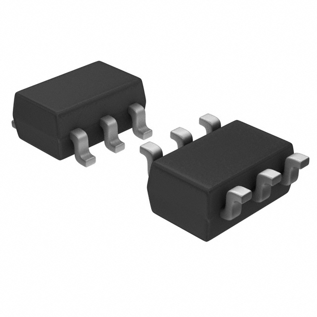


 工商网监
湘ICP备2023018690号
工商网监
湘ICP备2023018690号
