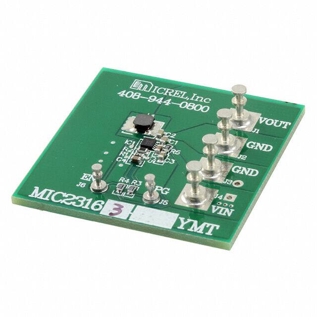
MIC23163/4 Evaluation Board
4MHz PWM 2A Buck Regulator with
HyperLight Load® and Power Good
General Description
Getting Started
The MIC23163/4 evaluation board allows the customer to
evaluate a fully-integrated 2A, 4MHz synchronous buck
®
regulator that features HyperLight Load mode, a Power
Good output indicator, and programmable soft-start. The
MIC23163/4 is highly efficient throughout the output
current range. The tiny 2mm x 2mm DFN package, in
combination with the 4MHz switching frequency, provides
a compact sub-1mm height solution that requires few
external components. The MIC23163/4 has a maximum
100% duty cycle and incorporates an active discharge
feature. It provides accurate output voltage regulation
under the most demanding conditions and responds
extremely quickly to a load transient with exceptionally
small output voltage ripple.
1. Connect an external supply to the VIN (J4) and GND
(J3) terminals.
With the output of the power supply disabled, set its
voltage to the desired input test voltage (2.7V ≤ VIN ≤
5.5V). An ammeter may be placed between the input
supply and the VIN (J4) terminal. Be sure to monitor
the supply voltage at the VIN (J4) terminal, as the
ammeter and/or power lead resistance can reduce the
voltage supplied to the device.
Requirements
The MIC23156 evaluation board requires a single 15W
bench power source adjustable from 2.7V to 5.5V. The
loads can either be active (electronic load) or passive
(resistor), and must be able to dissipate 10W. It is ideal,
but not essential, to have an oscilloscope available to view
the circuit waveforms. The simplest tests require two
voltage meters to measure input and output voltages.
Efficiency measurements require two voltage meters and
two ammeters to prevent errors caused by measurement
inaccuracies.
Precautions
There is no reverse input protection on this board. Be
careful when connecting the input source to ensure correct
polarity is observed.
Datasheets and support documentation are available on
Micrel’s web site at: www.micrel.com.
2. Connect a load to the VOUT (J1) and GND (J2)
terminals.
The load can be either passive (resistive) or active
(electronic load). An ammeter may be placed between
the load and the output terminal. Make sure the output
voltage is monitored at the VOUT (J1) terminal.
3. Enable the MIC23163/4.
The MIC23163/4 evaluation board has a pull-up
resistor to VIN. By default, the output voltage is
enabled when the input supply of >2.7V is applied. To
disable the device, apply a voltage below 0.5V to the
EN (J6) terminal.
4. Power Good.
A PG test point (J5) is provided to monitor the Power
Good feature. The Power Good output will go high
(VOUT) approximately 90µs after the output voltage
reaches 92% of its nominal voltage.
Ordering Information
Part Number
Description
MIC23163YMT EV
MIC23163 Evaluation Board
MIC23164YMT EV
MIC23164 Evaluation Board
HyperLight Load is a registered trademark of Micrel, Inc.
Micrel Inc. • 2180 Fortune Drive • San Jose, CA 95131 • USA • tel +1 (408) 944-0800 • fax + 1 (408) 474-1000 • http://www.micrel.com
August 23, 2013
Revision 1.0
�Micrel, Inc.
MIC23156 Evaluation Board
The feedforward capacitor, C4, provides essential
compensation for the MIC23163/4. A typical value range of
15pF to 68pF is recommended.
Evaluation Board
Power Good (PG)
The evaluation board has a test point provided for testing
the Power Good feature. This is an open-drain connection
with an on-board pull-up resistor of 100kΩ to the output
voltage. Power Good is asserted high approximately 90µs
after the output voltage passes 92% of the nominal set
voltage.
HyperLight Load Mode
MIC23156 uses a minimum on and off time proprietary
control loop (patented by Micrel). When the output voltage
falls below the regulation threshold, the error comparator
begins a switching cycle that turns the PMOS on and
keeps it on for the duration of the minimum-on-time. This
increases the output voltage. If the output voltage is more
than the regulation threshold, then the error comparator
turns the PMOS off for a minimum-off-time until the output
drops below the threshold. The NMOS acts as an ideal
rectifier that conducts when the PMOS is off. Using an
NMOS switch instead of a diode allows for lower voltage
drop across the switching device when the NMOS is on.
The asynchronous switching combination between the
PMOS and the NMOS allows the control loop to work in
discontinuous mode for light load operations. In
discontinuous mode, the MIC23163/4 works in pulse
frequency modulation (PFM) to regulate the output. As the
output current increases, the off-time decreases. This
provides more energy to the output. This switching
scheme improves the efficiency of MIC231563/4 during
light load currents by only switching when it is needed.
Features
Soft-Start Capacitor (C3)
The soft start (SS) pin is used to control the output voltage
ramp-up time. Setting C3 to 1nF sets the start-up time to
the minimum. The start-up time can be determined by
Equation 1:
TSS = 250 × 10 3 × ln(10 ) × C SS
Eq. 1
As the load current increases, the MIC23163/4 goes into
continuous conduction mode (CCM) and switches at a
frequency centered at 4MHz. The f to calculate the load
when the MIC23163/4 goes into continuous conduction
mode is approximated by Equation 2:
The action of the soft-start capacitor is to control the rise
time of the internal reference voltage between 0% and
100% of its nominal steady state value.
Feedback Resistors (R1, R2)
The output voltage is set nominally to 1.8V. This output
can be changed by adjusting the upper resistor, R1, in the
feedback potential divider. Therefore:
(V − VOUT ) × D
ILOAD > IN
2L × f
R1
VOUT = VREF × 1 +
R2
Eq. 2
As shown in Equation 2, the load at which MIC23163/4
transitions from HyperLight Load mode to PWM mode is a
function of the input voltage (VIN), output voltage (VOUT),
duty cycle (D), inductance (L), and frequency (f).
Where VREF = 0.7V
Table 1. Example Feedback Resistor Values
VOUT
R1
R2
1.2V
215k
301k
1.5V
301k
261k
1.8V
340k
215k
2.5V
274k
107k
3.3V
383k
102k
August 23, 2013
2
Revision 1.0
�Micrel, Inc.
MIC23156 Evaluation Board
Evaluation Board Schematic
Bill of Materials
Item
C1
C2
C3
C4
C5
L1
Part Name
C1608X5R0J475K
Manufacturer
TDK
(2)
GRM188R60J475KE19D
Murata
C1608X5R0J106K080AB
TDK
GRM188R60J106ME84D
Murata
GRM188R71H102MA01D
Murata
06035C102KAT2A
AVX
06035A150KAT2A
GRM1885C1H150JA01D
C1608X7R1A105K
GRM188R71A105KA61D
FLF3215T-R47N
LQH32PNR47NNC
R1
CRCW0603301KFKEA
R2
CRCW0603158KFKEA
R3, R4
Description
Qty.
(1)
(3)
AVX
Murata
TDK
Murata
4.7µF, 6.3V, X5R, Size 0603
1
10µF, 6.3V, X5R, Size 0603
1
1nF/50V, X7R, 0603
1
15pF, 50V, 0603
1
1µF, 10V, X7R, Size 0603
1
TDK
0.47µH, 2.8A, 21mΩ, L3.2mm x W2.5mm x H1.55mm
Murata
0.47µH, 2.9A, 24mΩ, L3.2mm x W2.5mm x H1.55mm
(4)
Vishay
1
301kΩ, 1%, 1/10W, Size 0603
1
Vishay
158kΩ, 1%, 1/10W, Size 0603
1
CRCW0603100KFKEA
Vishay
100kΩ, 1%, 1/10W, Size 0603
1
R5
CRCW060310R0FKEA
Vishay
10Ω, 1%, 1/10W, Size 0603
1
U1
MIC23163YMT
4MHz 2A Adjustable Buck Regulator with HyperLight
Load Mode
1
(5)
Micrel, Inc.
Notes:
1. TDK: www.tdk.com.
2. Murata: www.murata.com.
3. AVX: www.avx.com.
4. Vishay: www.vishay.com.
5. Micrel, Inc.: www.micrel.com.
August 23, 2013
3
Revision 1.0
�Micrel, Inc.
MIC23156 Evaluation Board
PCB Layout Recommendations
Top Layer
Bottom Layer
August 23, 2013
4
Revision 1.0
�Micrel, Inc.
MIC23156 Evaluation Board
MICREL, INC. 2180 FORTUNE DRIVE SAN JOSE, CA 95131 USA
TEL +1 (408) 944-0800 FAX +1 (408) 474-1000 WEB http://www.micrel.com
Micrel makes no representations or warranties with respect to the accuracy or completeness of the information furnished in this data sheet. This
information is not intended as a warranty and Micrel does not assume responsibility for its use. Micrel reserves the right to change circuitry,
specifications and descriptions at any time without notice. No license, whether express, implied, arising by estoppel or otherwise, to any intellectual
property rights is granted by this document. Except as provided in Micrel’s terms and conditions of sale for such products, Micrel assumes no liability
whatsoever, and Micrel disclaims any express or implied warranty relating to the sale and/or use of Micrel products including liability or warranties
relating to fitness for a particular purpose, merchantability, or infringement of any patent, copyright or other intellectual property right.
Micrel Products are not designed or authorized for use as components in life support appliances, devices or systems where malfunction of a product
can reasonably be expected to result in personal injury. Life support devices or systems are devices or systems that (a) are intended for surgical
implant into the body or (b) support or sustain life, and whose failure to perform can be reasonably expected to result in a significant injury to the user. A
Purchaser’s use or sale of Micrel Products for use in life support appliances, devices or systems is a Purchaser’s own risk and Purchaser agrees to fully
indemnify Micrel for any damages resulting from such use or sale.
© 2013 Micrel, Incorporated.
August 23, 2013
5
Revision 1.0
�