MIC2569
CableCARD™ Power Switch
General Description
Features
MIC2569 is designed to supply power to OpenCable™
systems and CableCARD™ hosts. These CableCARDs
are also known as Point of Distribution (POD) cards.
•
•
•
•
•
•
•
•
•
•
•
•
•
•
•
MIC2569 supports both Single and Multiple stream cards
through a simple to control parallel interface. All voltage
switching is soft-start at turn-on, and break-before-make
when changing between different voltage supplies.
Built in current limiting protects all VCC and VPP output lines
of the host system from card faults and accidental short
circuits. MIC2569 provides a FAULT/ signal to indicate an
over-current or fault condition exists and is equipped with
internal thermal monitoring circuitry to protect the device
itself in the event of a sustained over-current condition.
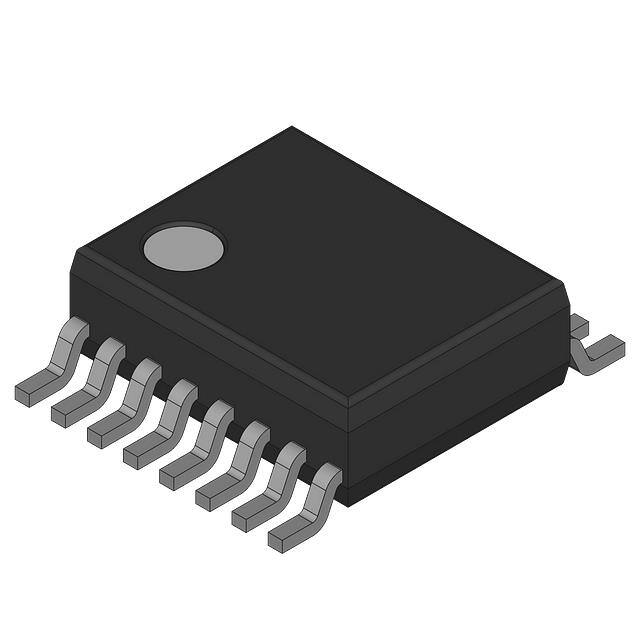
MIC2569 is offered in a space saving 16 pin QSOP
packaging.
Data sheets and support documentation can be found on
Micrel’s web site at www.micrel.com.
110 mΩ maximum VCC on resistance
400 mΩ maximum VPP on resistance
3.0V to 3.6V for the 3.3VIN operating range
3.0V to 5.5V for the 5VIN operating range
1.3A minimum VCC current limit
150mA minimum VPP current limit (150mA each)
Compact 16-pin QSOP packaging
Operating temperatures from –40°C to +85°C
Low quiescent current
Soft start turn-on
Break-before-make voltage switching
Short-circuit protection with thermal shutdown
Input under voltage lock-out (UVLO)
ESD protection
No external components required
Applications
• Satellite / Cable / DVR / Television set top boxes
• Video recorders
• Game consoles
___________________________________________________________________________________________________________
Typical Application
OpenCable Power Switch
CableCARD is a trademark of CableLabs, Inc.
OpenCable is a trademark of Cable Television Laboratories, Inc.
Micrel Inc. • 2180 Fortune Drive • San Jose, CA 95131 • USA • tel +1 (408) 944-0800 • fax + 1 (408) 474-1000 • http://www.micrel.com
September 2007
M9999-092507-C
(408) 944-0800
�Micrel, Inc.
MIC2569
Ordering Information
Part Number
Marking
Pb-Free
Junction Temp.
(1)
Range
Package
MIC2569YQS
MIC2569YQS
Yes
–40°C to +85°C
16-pin QSOP
Pin Configuration
16-Pin QSOP (QS)
September 2007
2
M9999-092507-C
(408) 944-0800
�Micrel, Inc.
MIC2569
Pin Description
Pin Number
Pin Name
Pin Function
1
GND
Ground.
2
NIC
No internal connection. A voltage or signal applied to this pin will have no effect
on device operation.
3
3.3VIN
4
5VIN
5
3.3VIN
6
NIC
3V Supply input. Internal chip power is drawn from this supply.
5V Supply input.
3V Supply input.
Note: both 3.3VIN inputs must be powered to insure rated current and RON is
met.
No internal connection. A voltage or signal applied to this pin will have no effect
on device operation.
Control Pins
7
8
9
C1
C2
C0
Outputs
C2
C1
C0
VCC
VPP1
VPP2
0
0
0
3.3 V
3.3 V
3.3 V
0
0
1
3.3 V
5.0 V
5.0 V
0
1
0
Hi-Z
Hi-Z
Hi-Z
0
1
1
Hi-Z
GND
Hi-Z
1
0
0
3.3 V
GND
5.0 V
1
0
1
3.3V
5V
GND
1
1
0
3.3V
GND
GND
1
1
1
GND
GND
GND
FAULT/ indicates the occurrence of a fault. FAULT/ is an open drain LOW true
output and goes low when any supply output is in current limit or if a thermal fault
occurs.
10
FAULT/
11
NIC
12
VPP2
VPP2 output to CableCARD™ card.
VCC
VCC (3V main supply) output to CableCARD™ card. Both output pins should be
connected together.
15
NIC
No internal connection. A voltage or signal applied to this pin will have no effect
on device operation.
16
VPP1
13
14
September 2007
No internal connection. A voltage or signal applied to this pin will have no effect
on device operation.
VPP1 output to CableCARD™ card.
3
M9999-092507-C
(408) 944-0800
�Micrel, Inc.
MIC2569
Absolute Maximum Ratings(1)
Operating Ratings(2)
Power Supply Voltage
5VIN ........................................................-0.3V to +6.0V
3.3VIN .....................................................-0.3V to +3.8V
Voltage on any other pin................................-0.3V to +6.0V
Continuous Output Current:
VCC ................................................................................. Internally limited
VPP ......................................................Internally limited
Current Into/Out of any control pin: .......................... ±10mA
Junction Temperature ................................................150°C
Storage Temperature .............................. –65°C to +150°C
Power Supply Voltage
5VIN............................................................................................ 3.0V to 5.5V
3.3VIN ........................................................ 3.0V to 3.6V
Continuous Output Current
VCC ............................................................................................................. 3.3A
VPP .................................................................. 450 mA
Ambient Temperature (TA)...........................–40°C to +85°C
Junction Temperature (TJ).........................–40°C to +125°C
Thermal Resistance (θJA).................................... 100.8°C/W
Soldering: QSOP Packages
(3)
Infrared (10 to 20 seconds)......................260°C Peak
Electrical Characteristics(4)
3.3VIN = 3.3V; 5VIN = 5.0V; TA = 25°C. Bold values indicate –40°C ≤ TA ≤ +85°C.
Symbol
Parameter
Min
Typ
Max
Units
3.3VIN
Operating input voltage
Condition
3.0
3.3
3.6
V
5VIN
Operating input voltage
3.0
5.0
5.5
V
S-Mode
I3.3VIN Supply Input Current
No Load
C2,C1,C0 =
M-Mode
IVIN
S-Mode
I
5VIN
Supply Input Current
UVLO
Under Voltage Lock Out
UVLOHYS
Hysteresis
No Load
C2,C1,C0 =
M-Mode
000
140
220
µA
001
110
200
µA
010
80
220
µA
100
100
220
µA
111
90
180
µA
000
10
30
µA
001
50
150
µA
010
10
220
µA
100
35
220
µA
111
10
30
µA
3.3VIN rising
2.50
2.76
2.85
V
3.3VIN falling
2.45
2.69
2.80
V
80
mV
Power Switches
RDS_ON
ILIMIT
RON_VCC
VCC Switch Resistance:
RON_VPP1
VPP1 Switch Resistance:
IOUT = 1000 mA
80
110
mΩ
IOUT = 125 mA VOUT = 3.3 V
275
400
mΩ
IOUT = 125 mA VOUT = 5.0 V
275
400
mΩ
ILIMIT_VCC
Output Current Limit: VCC
VCC = 3.3 V
1.3
2.3
3.3
A
ILIMIT_VPP1
Output Current Limit: VPP1
VPP1 = 3.3 V and VPP1 = 5.0 V
150
300
450
mA
September 2007
4
M9999-092507-C
(408) 944-0800
�Micrel, Inc.
MIC2569
I/O Logic
Symbol
Parameter
VIL
LOW-Level Input Voltage
VIH
HIGH-Level Input Voltage
Condition
Min
Input Hysteresis
C2, C1, C0
I
Output OFF leakage current
FAULT/, VFAULT/ = 5V
Open Drain Output LOW
Voltage
FAULT/, I
V
OL_OD
Units
1
V
V
100
Input leakage Current
OFF
Max
2
I
IN_LGC
Typ
SINK
-1
4
= 1 mA
mV
+1
µA
10
µA
0.2
V
AC Characteristics
The S-Mode and M-Mode AC Characteristics are not tested in production, specified by design.
Symbol
Parameter
Condition
Min
Typ
Max
Units
tD_FAULT/
Delay before asserting or
deasserting FAULT/
Fault on VCC, VPP1, or VPP2
4
12
24
ms
Power-up Rise Time
No Power to VIN Compliance
Notes 5 & 6
750
µs
800
µs
000 to 001
Notes 8 & 9
800
µs
800
µs
001 to 000
Notes 8 & 10
35
µs
25
µs
001 to 110
Notes 8 & 10
35
µs
25
µs
100
µs
800
µs
S-Mode
tPWRUP_S-MODE_VCC
tPWRUP_S-MODE_VPP
tON_000-001_VPP
Output Turn On Delay Time
tR_000-001_VPP
Output Rise Time
tOFF_001-000_VPP
Output Turn-Off Delay
tF_001-000_VPP
Output Fall Time
t
Output Discharge Delay
t
Output Discharge Time
t
Output Turn On Delay Time
t
Output Rise Time
110 to 000
Notes 8 & 9
Symbol
Parameter
Condition
t
Output Turn On Delay Time
OFF_001-110_VPP
F_001-110_VPP
ON_110-000_VPP
R_110-000_VPP
M-Mode
ON_011-100_VCC
t
R_011-100_VCC
t
ON_011-100_VPP
Output Rise Time
Output Turn On Delay Time
t
Output Rise Time
tOFF_100-010_VCC
Output Turn-Off Delay
tF_100-010_VCC
Output Fall Time
tOFF_100-010_VPP
Output Turn-Off Delay
tF_100-010_VPP
Output Fall Time
R_011-100_VPP
September 2007
Min
Notes 5 & 6
011 to 100
Notes 8 & 9
Notes 5 & 7
100 to 010
Notes 8 & 10
5
Typ
Max
Units
50
µs
750
µs
800
µs
800
µs
35
µs
25
µs
35
µs
25
µs
M9999-092507-C
(408) 944-0800
�Micrel, Inc.
MIC2569
Symbol
Parameter
t
Output Discharge Delay
OFF_100-111_VCC
t
F_100-111_VCC
t
OFF_100-111_VPP
t
F_100-111_VPP
Output Discharge Time
Output Discharge Delay
Output Discharge Time
Condition
Min
Notes 5 & 7
100 to 111
Notes 8 & 10
Typ
Max
Units
35
µs
25
µs
35
µs
25
µs
Notes:
1. Exceeding the absolute maximum rating may damage the device.
2. The device is not guaranteed to function outside its operating rating.
3. Devices are ESD sensitive. Handling precautions recommended. Human body model, 1.5k in series with 100pF.
4. Specification for packaged product only.
5. RL = 10Ω, CL = 1µF, See Figures 1, 2.
6. Maximum transition time to 3.3 V compliance, from any state including VCC equal to GND.
7. Maximum transition time to GND, from any state including VCC equal to 3.6 V.
8. RL = 100Ω, CL = 0.1µF, See Figures 1, 2
9. Maximum transition time to 5 V compliance, from any state including VPP equal to GND.
10. Maximum transition time to GND, from any state including VPP equal to 5.5 V.
September 2007
6
M9999-092507-C
(408) 944-0800
�Micrel, Inc.
MIC2569
Timing Diagram
Figure 1. Turn-On and Turn-Off Delay
Figure 2. Rise and Fall Time
September 2007
7
M9999-092507-C
(408) 944-0800
�Micrel, Inc.
MIC2569
Typical Characteristics
September 2007
8
M9999-092507-C
(408) 944-0800
�Micrel, Inc.
September 2007
MIC2569
9
M9999-092507-C
(408) 944-0800
�Micrel, Inc.
MIC2569
Functional Characteristics
MIC2569 Block Diagram
September 2007
10
M9999-092507-C
(408) 944-0800
�Micrel, Inc.
Functional Description
3.3VIN and 5.0VIN
3.3VIN and 5VIN are the input power supplies for
the MIC2569.
3.3VIN powers the MIC2569’s
internal functions; as well as, VCC, and VPP1 and
VPP2. 5VIN provides power to VPP1 and VPP2.
Tables 1 and 2 shows the control states which
supply is provided to which output
C0, C1, C2 (States Controls)
C0, C1, and C2 control the output conditions for
VCC, VPP1 and VPP2. C0, C1, and C2 are inputs
to the MIC2569 provided by the host. See Tables 1
and 2 for a complete listing.
Also see the
Application Information section.
VCC
VCC provides the main 3.3V supply to the
CableCARD device. VCC is protected against high
current conditions and short circuits. The minimum
current limit is set to 1.3A from 3.3VIN. Breakbefore-make
switching
prevents
crossed
connections during state changes. The VCC output
depends on the host / card combination. See
Tables 1 and 2 for a complete listing. Also see the
Application Information section.
VPP1, VPP2 (VPP1/2)
VPP1 and VPP2 provide the 3.3V and 5.0V supplies
to the CableCARD device. VPP1 and VPP2 are
protected against high current conditions and short
circuits. The minimum current limit is set to a
minimum of 150mA. Note: VPP1 and VPP2 are
powered separately with each having a current limit
of 150mA Break-before-make switching prevents
crossed connections during state changes. The
VPP1/2 output depends on the host / card
combination. See Tables 1 and 2 for a complete
listing. Also see the Application Information section.
Soft-Start
The VCC, VPP1 and VPP2 outputs are all slew rate
September 2007
MIC2569
controlled insuring a soft-start turn-on characteristic.
Soft-starting is in effect anytime a supply ramps from a
0V condition or switches between voltages, as in the
case of the VPP outputs.
Thermal Shutdown
Because electrical faults can cause significant heating in
power switches, MIC2569 monitors its internal
temperature and will shut down should the die
temperature reach 140°C. When the die temperature
has dropped by about 10 degrees, MIC2569 will
reactivate its outputs. If there is still a problem, the
effected power switch will again get hot, shutting off all
outputs. This power cycling action will continue as long
as the fault persists. Once removed, MIC2569 will
resume normal operation.
FAULT/
FAULT/ is a LOW true open drain output which signals
an over current or over-temp condition. As an open drain
device, this output can be wire OR’d with other FAULT/
outputs to a single input pin on the host. For proper
operation this output must be pulled-up to the logic
supply rail by an external resistor. This resistor can be
large in value, but not so large that leakage currents
caused by surface contamination can cause a false
indication of a fault condition. For this reason it is
recommended that the pull-up resistor be 300kΩ or less.
FAULT/ is delayed with respect to an over current
condition being detected. This is to prevent brief current
spikes from triggering an interrupt to the system host.
The delay is on the order of 12ms. Any fault lasting over
8 ms triggers the FAULT/ output. There is no delay for
thermal faults. Any over-temp condition is reported
immediately.
UVLO (Under Voltage Lockout)
An under-voltage lock out (UVLO) circuit monitors the
3.3VIN rail and keeps MIC2569 disabled until the input
voltage reaches the minimum level needed for proper
operation. Below this voltage the output switches are
OFF and all functionality is disabled.
11
M9999-092507-C
(408) 944-0800
�Micrel, Inc.
MIC2569
S-Mode
System State
M-Mode
State
VCC
VPP1
VPP2
State
VCC
VPP1
VPP2
Power-up
000
3.3V
3.3V
3.3V
010
Hi-Z
Hi-Z
Hi-Z
No Card
000
3.3V
3.3V
3.3V
010
Hi-Z
Hi-Z
Hi-Z
Card Detect
000
3.3V
3.3V
3.3V
011
Hi-Z
GND
Hi-Z
After ID
000
3.3V
3.3V
3.3V
100
3.3V
GND
5V
CIS request
001
3.3V
5V
5V
▬
▬
▬
▬
Card removal
000
3.3V
3.3V
3.3V
111
GND
GND
GND
No Card
000
3.3V
3.3V
3.3V
010
Hi-Z
Hi-Z
Hi-Z
Table 1 Output States for S and M type CableCARD™s
Control
State
Control Pins
Outputs
C2
C1
C0
VCC
VPP1
VPP2
0
0
0
0
3.3V
3.3V
3.3V
1
0
0
1
3.3V
5V
5V
2
0
1
0
Hi-Z
Hi-Z
Hi-Z
3
0
1
1
Hi-Z
GND
Hi-Z
4
1
0
0
3.3V
GND
5V
5
1
0
1
3.3V
5V
GND
6
1
1
0
3.3V
GND
GND
7
1
1
1
GND
GND
GND
Table 2 Output Control
September 2007
12
M9999-092507-C
(408) 944-0800
�Micrel, Inc.
MIC2569
Figure 1 shows S-Mode power state diagram.
Application Information
CableCARD™ Operating Modes
The OpenCable system has a host component (S-Host
or M-Host) and a card component (S-Card or M-Card).
The host / card combination determines which
operational mode is used i.e. S-Mode or M-Mode. This
in turn determines the appropriate state diagram. Table
3 below shows all of the combinations and operating
modes.
S-Host
M-Host
S-Card
S-Mode
S-Mode or No power
M-Card
S-Mode
M-Mode
Table 3 Operating Mode Combinations
An M-Host has the choice to accept or not accept an SCard. If the M-Host accepts the S-Card then the M-Host
will initiate a change from M-Mode to S-Mode.
Otherwise, the M-Host will not power-up the S-Card.
Figure 1 S-Host Power State Diagram
M-Host
1. Power-up - Upon power-up, M-Host two options:
a. Move directly the state 2 [010]
b. Pass through state 7 [111] to remove any
excess voltage or charge, then move to
state 2 [010]
2. No Card – M-Host will remain in state 2 [010]
until card insertion.
3. Card Detection – If the M-Host detects that the
inserted card is an M-card, then the M- Host will
change to state 3 [011]. This informs the card
that the host is an M-Host.
4. Card ID – The M-Host uses the card
identification process to determine what type of
card it is and what modes the card can operate
in. There are three options:
a. If the card is an M-Card, then the MHost will change to state 4 [100] and
remain in state 4 [100] until card
removal.
b. If the card is an S-Card able to support
CH1, then the M-Host will reset the card
and power-up in S-Mode. The card will
remain in S-Mode until card removal.
c. If the card is not an M-Card, or an SCard not able to support Ch1, then
power will not be provided to the card.
The card will remain without power and
not change state until card removal.
S-Host
After power-up, the S-Host remains in state 0 [000]
unless one of two events occurs:
1. CIS Request – The CableCard™ may request
that the Vpp outputs be provided with 5VIN, that
is, enter state 1 [001]. It is the S-Host decision
whether to provide the Vpp outputs with 5VIN.
The S-Host has two possible options.
a. If the S-Host refuses to provide 5VIN,
then the S-Host does not change to
state 1 [001] and will remain in state
0 [000], even upon card removal. See
paragraph 2 below.
b. If the S-Host grants 5VIN, then S-Host
changes to state 1 [001]. The S-Host
remains in state 1 [001] without
returning. See paragraph 2 below.
2. Card removal – Upon card removal, the S-Host
has two possible options:
a. The S-Host changes directly to state
0 [000], regardless of the state at card
was removed.
b. The S-Host has the option to pass
through state 6 [110] to remove any
excessive voltage or charge on the Vpp
outputs. The S-Host then returns to
state 0 [000].
September 2007
13
M9999-092507-C
(408) 944-0800
�Micrel, Inc.
MIC2569
5. Card removal – Upon card removal the M-Host
will pass through state 7 [111] to remove any
excessive voltage or charge on the Vcc and Vpp
outputs. The M-Host then returns to state 2
[010].
Figure 2 below shows M-Mode power state diagram.
Figure 2 M-Host Power State Diagram
September 2007
14
M9999-092507-C
(408) 944-0800
�Micrel, Inc.
MIC2569
Package Information
16-Pin QSOP (QS)
MICREL, INC. 2180 FORTUNE DRIVE SAN JOSE, CA 95131 USA
TEL +1 (408) 944-0800 FAX +1 (408) 474-1000 WEB http://www.micrel.com
The information furnished by Micrel in this data sheet is believed to be accurate and reliable. However, no responsibility is assumed by Micrel for its
use. Micrel reserves the right to change circuitry and specifications at any time without notification to the customer.
Micrel Products are not designed or authorized for use as components in life support appliances, devices or systems where malfunction of a product
can reasonably be expected to result in personal injury. Life support devices or systems are devices or systems that (a) are intended for surgical implant
into the body or (b) support or sustain life, and whose failure to perform can be reasonably expected to result in a significant injury to the user. A
Purchaser’s use or sale of Micrel Products for use in life support appliances, devices or systems is a Purchaser’s own risk and Purchaser agrees to fully
indemnify Micrel for any damages resulting from such use or sale.
© 2007 Micrel, Incorporated.
September 2007
15
M9999-092507-C
(408) 944-0800
�