MIC2954
250mA Low-Dropout Regulator
General Description
Features
The MIC2954 is a “bulletproof” efficient voltage regulator
with very low dropout voltage (typically 40mV @ light loads
and 375mV @ 250mA), and low quiescent current (120µA
typical). The quiescent current of the MIC2954 increases
only slightly in dropout, thus prolonging battery life. Key
MIC2954 features include protection against reversed
battery, fold-back current limiting, and automotive load
dump protection (60V positive transient).
The MIC2954-07/08BM is an adjustable version that
includes an error flag output that warns of a low output
voltage, which is often due to failing batteries on the input.
This may also be used as a power-on reset. A logiccompatible shutdown input is provided which enables the
regulator to be switched on and off. This part may be pinstrapped for 5V output, or programmed from 1.24V to 29V
with the use of two external resistors.
The MIC2954 is available in two voltage tolerances, ±0.5%
maximum and ±1% maximum. Both are guaranteed for
junction temperatures from –40°C to +125°C.
Data sheets and support documentation can be found on
Micrel’s web site at www.micrel.com.
•
•
•
•
•
•
•
•
•
•
•
High-accuracy 5V, guaranteed 250mA output
Low quiescent current
Low dropout voltage
Extremely tight load and line regulation
Very low temperature coefficient
Current and thermal limiting
Input can withstand –20V reverse battery and+60V
positive transients
Error flag warns of low output voltage
Logic-controlled electronic shutdown
Output programmable from 1.24V to 29V
(MIC2954-07/08)
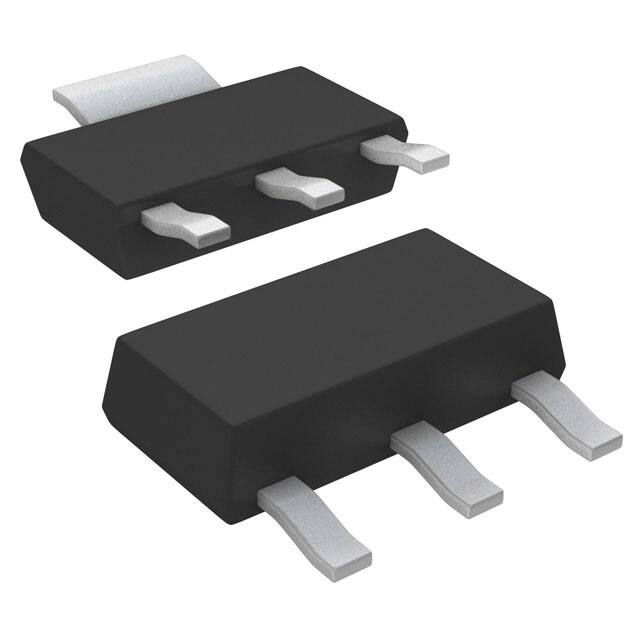
Available in TO-220, TO-92, and surface-mount SOT223 and SOIC-8 packages
Applications
• Battery powered equipment
• Cellular telephones
• Laptop, notebook, and palmtop computers
• PCMCIA VCC and VPP regulation/switching
• Bar code scanners
• Automotive electronics
• SMPS post-regulator/dc-to-dc modules
• Voltage reference
• High-efficiency linear power supplies
___________________________________________________________________________________________________________
Ordering Information
Part Number
Pb-Free /
Standard
RoHS Compliant
MIC2954-02BT
MIC2954-02WT*
MIC2954-03BT
MIC2954-03WT*
MIC2954-02BS
MIC2954-02WS*
MIC2954-03BS
MIC2954-03WS*
MIC2954-02BZ
MIC2954-02YZ
MIC2954-03BZ
MIC2954-03YZ
MIC2954-07BM
MIC2954-07YM
MIC2954-08BM
MIC2954-08YM
Accuracy
0.5%
1.0%
0.5%
1.0%
0.5%
1.0%
0.5%
1.0%
Junction
Temp. Range
–40° to +125°C
–40° to +125°C
–40° to +125°C
–40° to +125°C
–40° to +125°C
–40° to +125°C
–40° to +125°C
–40° to +125°C
Package
TO-220-3
TO-220-3
SOT-223-3
SOT-223-3
TO-92-3**
TO-92-3**
8-Pin SOIC
8-Pin SOIC
* RoHS compliant with ‘high-melting solder’ exemption.
** TO-92 package discontinuance notification issued September 2007. End-of-life-buy offered thru December 31, 2007.
Contact factory for additional information.
Micrel Inc. • 2180 Fortune Drive • San Jose, CA 95131 • USA • tel +1 (408) 944-0800 • fax + 1 (408) 474-1000 • http://www.micrel.com
September 2007
M9999-090607
�Micrel, Inc.
MIC2954
Typical Application
100k
VIN
VOUT
1.2V to 30V
MIC2954
8
3
SHUTDOWN
ENABLE
VERR
IN
OUT
SHDN ERR
1
FB
7
GND
R1
VOUT = VREF ⎛⎜1+ ⎞⎟
⎝ R2 ⎠
4
R1
5
VREF
100pF
10µF
R2
2, 6 = OPEN
5V Fixed Regulator
Adjustable Regulator
5V or 3V Selectable Regulator with Shutdown
Wide Input-Voltage-Range Current Limiter
September 2007
2
M9999-090607
�Micrel, Inc.
MIC2954
Pin Configuration
OUT 1
8 IN
SNS 2
7 FB
SHDN 3
6 TAP
GND 4
5 ERR
1
IN
3
3-Pin SOT-223 (S)
TO-92
3
OUT
2
GND
1
IN
TAB
8-Pin SOIC (M)
2
GND OUT
3-Pin TO-92 (Z)
3
OUT
2
GND
1
IN
3-Pin TO-220 (T)
Pin Description
Pin No.
SOIC-8
Pin No.
SOT-223
Pin No.
TO-92
Pin No.
TO-220
Pin Name
8
1
1
1
IN
4
2, TAB
2
2
GND
Ground.
1
3
3
3
OUT
Regulator Output.
2
SNS
Sense (Input): Output-sense-voltage end of internal resistive divider.
Connect to OUT (VOUT = 5V) for fixed5V operation; also see TAP.
Not used in adjustable configuration.
3
SHDN
Shutdown (Input): Active-low input enables regulator.
(Low = enable; high = shutdown.)
5
/ERR
Error Flag (Output): Open collector (active-low) output. Active state
indicates an output (VOUT) undervoltage condition.
(Low = error, floating = normal.)
6
TAP
Divider Tap (Output): Resistive voltage divider tap. With 5Vapplied to
SNS, VTAP is approximately 1.23V. Connect to FB for 5V operation.
Not used in adjustable configuration.
7
FB
Feedback (Input): Error amplifier input. Compared to internal1.23V
reference. Connect to external voltage divider for adjustable operation
or internal voltage divider (TAP) for 5V operation (see SNS, TAP).
September 2007
Pin Name
Supply Input.
3
M9999-090607
�Micrel, Inc.
MIC2954
Absolute Maximum Ratings(1)
Operating Ratings(2)
Supply Voltage (VIN) ....................................... –20V to +60V
Feedback Voltage (VFB) (14, 15)........................ –1.5V to +26V
Shutdown Input Voltage (VSHDN).................... –0.3V to +30V
Error Output Voltage (VERR) .......................... –0.3V to +30V
Power Dissipation (PD) (4) ..........................Internally Limited
Lead Temperature (soldering, 5 sec.)........................ 260°C
Storage Temperature (Ts) .........................–65°C to +150°C
ESD Rating(3)
Supply Voltage (VIN)...................................... +2.0V to +30V
Junction Temperature (TJ) ........................ –40°C to +125°C
Package Thermal Resistance (θJC, θJA) (5)
Electrical Characteristics
MIC2954-07/08: VFB = VTAP; VSNS = VOUT; VSHDN ≤ 0.6V. All versions: VIN = 6V; IL = 1mA; CL = 2.2µF; TJ = 25°C,
bold values indicate –40°C ≤ TJ ≤ +125°C; Note 8; unless noted.
Symbol
Parameter
Condition
VOUT
Output Voltage
MIC2954-02/-07 (±0.5%)
∆VOUT/∆T
∆VOUT/VOUT
∆VOUT/VOUT
VIN – VOUT
IGND
IGND(DO)
Min
Typ
Max
Units
4.975
4.940
5.000
5.025
5.060
V
V
MIC2954-02/-07 (±0.5%), 1mA ≤ IL ≤ 250mA
4.930
5.000
5.070
V
MIC2954-03/-08 (±1%)
4.950
4.900
5.000
5.050
5.100
V
V
MIC2954-03/-08 (±1%), 1mA ≤ IL ≤ 250mA
4.880
5.000
5.120
V
Output Voltage Temperature
Coefficient, Note 6
MIC2954-02/-07 (±0.5%)
20
100
ppm/°C
MIC2954-03/-08 (±1%)
20
150
ppm/°C
Line Regulation, Note 7
MIC2954-02/-07 (±0.5%), VIN = 6V to 26V
0.03
0.10
0.20
%/V
%/V
MIC2954-03/-08 (±1%), VIN = 6V to 26V
0.03
0.20
0.40
%/V
%/V
MIC2954-02/-07 (±0.5%), IL = 1 to 250mA
0.04
0.16
0.20
%/V
%/V
MIC2954-03/-08 (±1%), IL = 1 to 250mA
0.04
0.20
0.30
%/V
%/V
IL = 1mA
60
100
150
mV
mV
IL = 50mA
220
250
420
mV
mV
IL = 100mA
250
300
450
mV
mV
IL = 250mA
375
450
600
mV
mV
IL = 1mA
140
200
300
µA
µA
IL = 50mA
0.5
1
2
mA
mA
IL = 100mA
1.7
2.5
3.5
mA
mA
IL = 250mA
5
9
12
mA
mA
VIN = 4.5V
180
300
µA
Load Regulation, Note 8
Dropout Voltage, Note 9
Ground Pin Current, Note 10
Ground Pin Current at Dropout,
Note 10
September 2007
4
M9999-090607
�Micrel, Inc.
MIC2954
Symbol
Parameter
Condition
ILIMIT
Current Limit, Note 11
VOUT = 0V
∆VOUT/∆PD
Thermal Regulation, Note 12
en
Output Noise Voltage
(10Hz to 100kHz)
IL = 100mA, CL = 2.2µF
Reference Voltage
MIC2954-02/-07 (±0.5%)
1.220
1.200
1.235
1.250
1.260
V
V
MIC2954-03/-08 (±1%)
1.210
1.200
1.235
1.260
1.270
V
V
MIC2954-02/-07 (±0.5%), Note 13
1.190
1.270
V
MIC2954-03/-08 (±1%), Note 13
1.185
Reference Voltage
Min
0.05
Max
Units
750
800
mA
mA
0.2
%/W
400
IL = 100mA, CL = 33µF
µVRMS
260
Feedback Pin Bias Current
Reference Voltage
Temperature Coefficient,
Note 12
Typ
20
µVRMS
1.285
V
40
60
nA
nA
MIC2954-02/-07 (±0.5%)
20
ppm/°C
MIC2954-03/-08 (±1%)
50
ppm/°C
Feedback Pin Bias Current
Temperature Coefficient
0.1
40
nA/°C
Error Comparator
Output Leakage Current
VOH = 30V
0.01
1.00
2.00
µA
µA
Output Low Voltage
VIN = 4.5V, IOL = 400µA
150
250
400
mV
mV
Upper Threshold Voltage
Note 14
60
40
25
mV
mV
Lower Threshold Voltage
Note 14
75
95
140
mV
mV
Hysteresis
Note 14
15
mV
mV
Shutdown Input
Input Logic Voltage
low (on)
1.3
high (off)
Shutdown Pin Input Current
Regular Output Current in
Shutdown
September 2007
0.7
2.0
V
V
VSHDN = 2.4V
30
50
100
µA
µA
VSHDN = 30V
450
600
750
µA
µA
3
10
20
µA
µA
Note 15
5
M9999-090607
�Micrel, Inc.
MIC2954
Notes:
1. Exceeding the absolute maximum rating may damage the device.
2. The device is not guaranteed to function outside its operating rating.
3. Devices are ESD sensitive. Handling precautions recommended.
4. PD(max) = (TJ(max) – TA) ÷ θJC. Exceeding TJ(max) will cause thermal shutdown.
5. Thermal resistance (θJC) of the TO-220 package is 2.5°C/W, and 15°C/W for the SOT-223. Thermal resistance (θJC) of the TO-92 package is
180°C/W with 0.4" leads and 160°C/W with 0.25" leads. Thermal resistance (θJA) of the SOP-8 is 160°C/W mounted on a printed circuit board
(See “Application Information: Thermal Calculation”).
6. Output voltage temperature coefficient is defined as the worst case voltage change divide by the total temperature range.
7. Line regulation for the MIC2954 is tested at 125°C for IL = 1mA. For IL = 100µA and TJ = 125°C, line regulation is guaranteed by design to0.2%.
See “Typical Characteristics” for line regulation versus temperature and load current.
8. Regulation is measured at constant junction temperature using low duty cycle pulse testing. Changes in output voltage due to heating effects are
covered by the thermal regulation specification.
9. Dropout Voltage is defined as the input to output differential at which the output voltage drops 100 mV below its nominal value measured at 1V
differential. At very low values of programmed output voltage, the minimum input supply voltage of 2 V (2.3V over temperature) must be taken into
account.
10. Ground pin current is the regulator quiescent current. The total current drawn from the source is the sum of the load current plus the ground pin
current.
11. The MIC2954 features fold-back current limiting. The short circuit (VOUT = 0V) current limit is less than the maximum current with normal output
voltage.
12. Thermal regulation is defined as the change in output voltage at a time t after a change in power dissipation is applied, excluding load or line
regulation effects. Specifications are for a 200mA load pulse at VIN = 20V (a 4W pulse) for t = 10ms.
13. VREF ≤ VOUT ≤ (VIN – 1V), 2.3V ≤ VIN ≤ 30V, 100 µA < IL ≤ 250 mA, TJ ≤ TJ(max).
14. Comparator thresholds are expressed in terms of a voltage differential at the FB pin below the nominal reference voltage measured at 6Vinput. To
express these thresholds in terms of output voltage change, multiply by the error amplifier gain = VOUT /VREF = (R1 + R2)/R2. For example, at a
programmed output voltage of 5V, the error output is guaranteed to go low when the output drops by 95mV × 5V/1.235V = 384mV. Thresholds
remain constant as a percent of VOUT as VOUT is varied, with the dropout warning occurring at typically 5% below nominal, 7.5% guaranteed.
15. VSHDN ≥ 2V, VIN ≤ 30 V,VOUT = 0, with the FB pin connected to TAP.
16. When used in dual supply systems where the regulator load is returned to a negative supply, the output voltage must be diode clamped to ground.
17. Maximum positive supply voltage of 60V must be of limited duration (