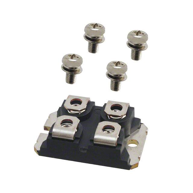
MSC50DC120HJ SiC Diode Full Bridge Power Module
1
Product Overview
This section provides the product overview for the MSC50DC120HJ device.
All ratings at Tj = 25 °C, unless otherwise specified.
Caution: These devices are sensitive to electrostatic discharge. Proper handling procedures should be
followed.
MSCC-0344-DS-01018 Datasheet Revision 1.0
1
�1.1
Features
The following are key features of the MSC50DC120HJ device:
Silicon carbide (SiC) Schottky diode
Zero reverse recovery
Zero forward recovery
Temperature-independent switching behavior
Positive temperature coefficient on VF
Very low stray inductance
High level of integration
1.2
Benefits
The following are benefits of the MSC50DC120HJ device:
Outstanding performance at high-frequency operation
Direct mounting to heatsink (isolated package)
Low junction-to-case thermal resistance
RoHS compliant
1.3
Applications
The MSC50DC120HJ device is designed for the following applications:
Switch mode power supplies rectifier
Induction heating
Welding equipment
High-speed rectifiers
MSCC-0344-DS-01018 Datasheet Revision 1.0
2
�2
Electrical Specifications
This section provides the electrical specifications for the MSC50DC120HJ device.
2.1
Absolute Maximum Ratings
The following table shows the absolute maximum ratings per diode for the MSC50DC120HJ device.
Table 1 • Absolute Maximum Ratings
Symbol
Parameter
Maximum Ratings
Unit
VRRM
Repetitive peak reverse voltage
1200
V
IF
DC forward current
50
A
TC = 60 °C
The following table shows the thermal and package characteristics of the MSC50DC120HJ.
Table 2 • Thermal and Package Characteristics
2.2
Symbol
Characteristic
Min
Typ
Max
VISOL
RMS isolation voltage, any terminal to case t =1
minute, 50 Hz/60 Hz
2500
TJTSTG
Storage temperature range
–55
175
TJOP
Recommended junction temperature under
switching conditions
–55
TJmax–25
Torque
Terminal and mounting screws
Wt
Package weight
Unit
V
°C
1.1
N.m
29.2
g
Electrical Performance
The following table shows the electrical characteristics per diode of the MSC50DC120HJ.
Table 3 • Electrical Characteristics Per Diode
Symbol
Characteristic
Test Conditions
VF
Diode forward voltage
IF = 50 A
IRM
Reverse leakage current
VR = 1200 V
Min
Typ
Max
Unit
Tj = 25 °C
1.5
1.8
V
Tj = 175 °C
2.1
Tj = 25 °C
15
200
μA
Tj = 175 °C
250
QC
Total capacitive charge
VR = 600 V
224
nC
C
Total capacitance
f = 1 MHz, VR = 400 V
246
pF
f = 1 MHz, VR = 800 V
182
RthJC
Junction-to-case thermal resistance
MSCC-0344-DS-01018 Datasheet Revision 1.0
0.95
°C/W
3
�2.3
Performance Curves
This section shows the typical performance curves for the MSC50DC120HJ device.
Figure 1 • Maximum Transient Thermal Impedance
Figure 2 • Forward Current vs. Forward Voltage
Figure 3 • Capacitance vs. Reverse Voltage
MSCC-0344-DS-01018 Datasheet Revision 1.0
4
�3
Package Specifications
This section shows the package specifications for the MSC50DC120HJ device.
3.1
Package Outline Drawing
The following drawing shows the package outline of the MSC50DC120HJ device. The dimensions in the
following figure are in millimeters.
Figure 4 • Package Outline Drawing
MSCC-0344-DS-01018 Datasheet Revision 1.0
5
�Microsemi Headquarters
One Enterprise, Aliso Viejo,
CA 92656 USA
Within the USA: +1 (800) 713-4113
Outside the USA: +1 (949) 380-6100
Sales: +1 (949) 380-6136
Fax: +1 (949) 215-4996
Email: sales.support@microsemi.com
www.microsemi.com
© 2019 Microsemi. All rights reserved. Microsemi and the Microsemi logo
are trademarks of Microsemi Corporation. All other trademarks and service
marks are the property of their respective owners.
Microsemi makes no warranty, representation, or guarantee regarding the information contained herein or the suitability of its products and services
for any particular purpose, nor does Microsemi assume any liability whatsoever arising out of the application or use of any product or circuit. The
products sold hereunder and any other products sold by Microsemi have been subject to limited testing and should not be used in conjunction with
mission-critical equipment or applications. Any performance specifications are believed to be reliable but are not verified, and Buyer must conduct and
complete all performance and other testing of the products, alone and together with, or installed in, any end-products. Buyer shall not rely on any data
and performance specifications or parameters provided by Microsemi. It is the Buyer's responsibility to independently determine suitability of any
products and to test and verify the same. The information provided by Microsemi hereunder is provided "as is, where is" and with all faults, and the
entire risk associated with such information is entirely with the Buyer. Microsemi does not grant, explicitly or implicitly, to any party any patent rights,
licenses, or any other IP rights, whether with regard to such information itself or anything described by such information. Information provided in this
document is proprietary to Microsemi, and Microsemi reserves the right to make any changes to the information in this document or to any products
and services at any time without notice.
Microsemi, a wholly owned subsidiary of Microchip Technology Inc. (Nasdaq: MCHP), offers a comprehensive portfolio of semiconductor and system
solutions for aerospace & defense, communications, data center and industrial markets. Products include high-performance and radiation-hardened
analog mixed-signal integrated circuits, FPGAs, SoCs and ASICs; power management products; timing and synchronization devices and precise time
solutions, setting the world's standard for time; voice processing devices; RF solutions; discrete components; enterprise storage and communication
solutions; security technologies and scalable anti-tamper products; Ethernet solutions; Power-over-Ethernet ICs and midspans; as well as custom design
capabilities and services. Microsemi is headquartered in Aliso Viejo, California, and has approximately 4,800 employees globally. Learn more at www.
microsemi.com.
MSCC-0344-DS-01018 | June 2019 | Final
MSCC-0344-DS-01018 Datasheet Revision 1.0
6
�
很抱歉,暂时无法提供与“MSC50DC120HJ”相匹配的价格&库存,您可以联系我们找货
免费人工找货