0
登录后你可以
  • 下载海量资料
  • 学习在线课程
  • 观看技术视频
  • 写文章/发帖/加入社区
会员中心
创作中心
发布
  • 发文章

  • 发资料

  • 发帖

  • 提问

  • 发视频

创作活动
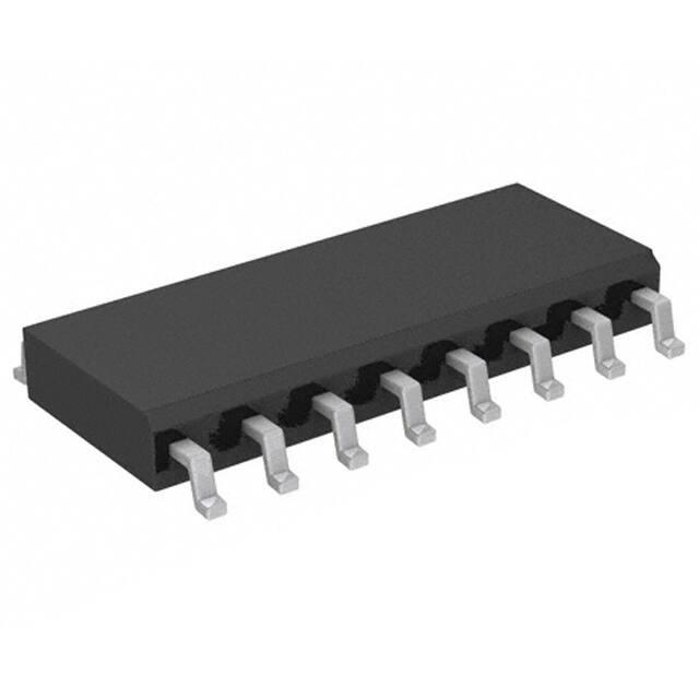
PL123-09HSI

PL123-09HSI

  • 厂商:

    ACTEL(微芯科技)

  • 封装:

    SOIC16

  • 描述:

    IC CLK MULTPLX 1:9 134MHZ 16SOIC

  • 详情介绍
  • 数据手册
  • 价格&库存
PL123-09HSI 数据手册
PL123-05/-09 Low Skew Zero Delay Buffer FEATURES DESCRIPTION   The PL123-05/-09 (-05H/-09H for High Drive) are high performance, low skew, low jitter zero delay buffers designed to distribute high speed clocks. They have one (PL123-05) or two (PL123-09) low-skew output banks, of 4 outputs each, that are synchronized with the input. The PL123-09 allows control of the banks of outputs by using the S1 and S2 inputs as shown in the Selector Definition table on page 2.      Frequency Range 10MHz to 134 MHz Output Options: o 5 outputs PL123-05 o 9 outputs PL123-09 Zero input - output delay Optional Drive Strength: Standard (8mA) PL123-05/-09 High (12mA) PL123-05H/-09H 3.3V, ±10% operation Available in Commercial and Industrial temperature ranges Available in 16-Pin SOP or TSSOP (PL123-09), and 8-Pin SOP (PL123-05) packages The synchronization is established via CLKOUT feed back to the input of the PLL. Since the skew between the input and output is less than 100ps, the device acts as a zero delay buffer. The input output propagation delay can be advanced or delayed by adjusting the load on the CLKOUT pin. These parts are not intended for 5V input-tolerant applications. BLOCK DIAGRAM Mux CLKOUT CLKA2 CLKA3 Bank A CLKA1 CLKA4 (PL123-09 Only) CLKB2 CLKB3 CLKB4 Bank B S2 Selector Inputs 1 2 CLKA1 3 GND 4 8 CLKOUT 7 CLKA4 6 VDD 5 CLKA3 REF 1 16 CLKOUT CLKA1 2 15 CLKA4 CLKA2 3 14 CLKA3 13 VDD 12 GND PL123-09 S1 CLKB1 REF CLKA2 PL123-05 PLL REF VDD 4 GND 5 CLKB1 6 11 CLKB4 CLKB2 7 10 CLKB3 S2 8 9 S1 Micrel Inc. • 2180 Fortune Drive • San Jose, CA 95131 • USA • tel +1(408) 944 -0800 • fax +1(408) 474-1000 • www.micrel.com Rev 4/22/13 Page 1 PL123-05/-09 Low Skew Zero Delay Buffer PIN DESCRIPTIONS PL123-09 Name PL123-05 Type Description TSSOP-16L SOP-16L SOP-8L REF [1] 1 1 1 I Input reference frequency. CLKA1 [2] 2 2 3 O Buffered clock output, Bank A CLKA2 [2] 3 3 2 O Buffered clock output, Bank A VDD 4,13 4,13 6 P VDD connection GND 5,12 5,12 4 P GND connection CLKB1 [2] 6 6 - O Buffered clock output, Bank B CLKB2 [2] 7 7 - O Buffered clock output, Bank B S2 [3] 8 8 - I Selector input S1 [3] 9 9 - I Selector input CLKB3 [2] 10 10 - O Buffered clock output, Bank B CLKB4 [2] 11 11 - O Buffered clock output, Bank B CLKA3 [2] 14 14 5 O Buffered clock output, Bank A CLKA4 [2] 15 15 7 O CLKOUT [2] 16 16 8 O Buffered clock output, Bank A Buffered clock output. Internal feedback on this pin. Notes: 1: Weak pull-down. 2: Weak pull-down on all outputs. 3: Weak Pull-Up on S1 and S2 SELECTOR DEFINITION FOR PL123-09 S2 S1 CLOCK A1–A4 (Bank A) CLOCK B1–B4 (Bank B) CLKOUT Output Source PLL Shutdown 0 0 Three-state Three-state Driven PLL N 0 1 Driven Three-state Driven PLL N 1 0 Driven Driven Driven Reference Y 1 1 Driven Driven Driven PLL N INPUT / OUTPUT SKEW CONTROL The PL123-05/-09 will achieve Zero Delay from input to output when all the outputs are loaded equally . Adjustments to the input/output delay can be made by adding additional loading to the CLKOUT pin. Please contact Micrel for more information. Micrel Inc. • 2180 Fortune Drive • San Jose, CA 95131 • USA • tel +1(408) 944 -0800 • fax +1(408) 474-1000 • www.micrel.com Rev 4/22/13 Page 2 PL123-05/-09 Low Skew Zero Delay Buffer LAYOUT RECOMMENDATIONS The following guidelines are to assist you with a performance optimized PCB design: Signal Integrity and Termination Considerations Decoupling and Power Supply Considerations - Keep traces short! - Place decoupling capacitors as close as possible to the VDD pin(s) to limit noise from the power supply - Trace = Inductor. With a capacitive load this equals ringing! - Long trace = Transmission Line. Without proper termination this will cause reflections ( looks like ringing ). - Design long traces as “striplines” or “microstrips” with defined impedance. - Match trace at one side to avoid reflections bouncing back and forth. - Addition of a ferrite bead in series with VDD can help prevent noise from other board sources - Value of decoupling capacitor is frequency dependant. Typical values to use are 0.1F for designs using frequencies < 50MHz and 0.01F for designs using frequencies > 50MHz. Typical CMOS termination Place Series Resistor as close as possible to CMOS output CMOS Output Buffer To CMOS Input ( Typical buffer impedance 20  50 line Connect a 33 series resistor at each of the output clocks to enhance the stability of the output signal Micrel Inc. • 2180 Fortune Drive • San Jose, CA 95131 • USA • tel +1(408) 944 -0800 • fax +1(408) 474-1000 • www.micrel.com Rev 4/22/13 Page 3 PL123-05/-09 Low Skew Zero Delay Buffer ABSOLUTE MAXIMUM CONDITIONS Supply Voltage to Ground Potential ...... –0.5V to 4.6V DC Input Voltage ........................... V SS – 0.5V to 4.6V Storage Temperature ........................ –65°C to 150°C Junction Temperature………………………….. 150°C Static Discharge Voltage (per MIL-STD-883, Method 3015)…………..> 2000V OPERATING CONDITIONS Parameter Description Min. Max. Unit V DD Supply Voltage 3.0 3.6 V 0 70 C Industrial Operating Temperature (ambient temperature) -40 85 C Load Capacitance, below 100 MHz Load Capacitance, above 100 MHz Input Capacitance Power-up time for all V DD s to reach minimum specified voltage (power ramps must be monotonic) ― ― ― 30 10 7 pF pF pF 0.05 250 ms TA CL C IN t PU Commercial Operating Temperature (ambient temperature) ELECTRICAL CHARACTERISTICS Parameter Test Conditions Description Min. Max. Unit VIL Input LOW Voltage – 0.8 V VIH Input HIGH Voltage 2.5 – V IIL Input LOW Current VIN = 0V – 50 µA IIH Input HIGH Current – 100 µA VOL Output LOW Voltage[4] – 0.4 V VOH Output HIGH Voltage[4] 2.4 – V Supply Current (Unloaded Outputs) – 32 mA IDD VIN = VDD IOL = 8 mA IOL = 12 mA IOH = –8 mA IOL = –12 mA 66.67MHz with unloaded outputs Commercial Temp. 66.67MHz with unloaded outputs Industrial Temp. – 45 mA Notes: 4. Parameter is guaranteed by design and c haracterization. Not 100% tested in production. Micrel Inc. • 2180 Fortune Drive • San Jose, CA 95131 • USA • tel +1(408) 944 -0800 • fax +1(408) 474-1000 • www.micrel.com Rev 4/22/13 Page 4 PL123-05/-09 Low Skew Zero Delay Buffer SWITCHING CHARACTERISTICS Parameter Name t1 t3 t4 t5 t6A t6B [5] Test Conditions Min. Typ. Max. Unit 30-pF load 10 – 100 MHz 10-pF load 10 – 134 MHz Duty Cycle [4] = t2 ÷ t1 Measured at 1.4V, FOUT = 66.67MHz 40 50 60 % Duty Cycle Measured at 1.4V, FOUT
PL123-09HSI
物料型号:MICREL PL123-05/-09

器件简介: - 该器件是高性能、低偏差、低抖动的零延迟缓冲器,设计用于分发高速时钟信号。 - PL123-05/-09具有一个或两个低偏差输出组,每组4个输出,与输入同步。 - 通过CLKOUT反馈到PLL的输入来建立同步,输入和输出之间的偏差小于±100ps。

引脚分配: - PL123-05/-09有16个引脚,包括参考频率输入、时钟输出、电源连接、地连接、选择输入等。 - 引脚具有弱上拉或下拉功能,以确保信号稳定性。

参数特性: - 工作频率范围:10MHz至134MHz。 - 输出选项:PL123-05有5个输出,PL123-09有9个输出。 - 可选的驱动强度:标准型(8mA)和高驱动型(12mA)。 - 3.3V±10%的电源操作。 - 适用于商业和工业温度范围。 - 封装类型:16引脚SOP或TSSOP(PL123-09),8引脚SOP(PL123-05)。

功能详解: - 该器件不是为5V输入容忍应用设计的。 - 通过调整CLKOUT引脚上的负载,可以提前或延迟输入输出传播延迟。

应用信息: - 适用于需要高速时钟信号同步的场合,如高性能通信设备、数据转换器等。

封装信息: - 提供8引脚SOP、16引脚SOP和16引脚TSSOP封装选项。
PL123-09HSI 价格&库存

很抱歉,暂时无法提供与“PL123-09HSI”相匹配的价格&库存,您可以联系我们找货

免费人工找货