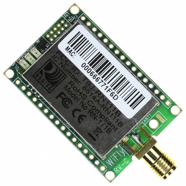
RN-111B
www.rovingnetworks.com
DS-RN111B_V1 4/20/2009
“WiFly” 802.11B Module
Features
•
Ultra-low power module with 40mA average
RX, 120ma TX burst current usage.
•
Applications
•
Wireless thermostats
Embedded stacks with TCP/UDP/IP, sockets,
no host or processor stacks required.
•
RS232/RS485 cable replacement
•
Remote equipment monitoring
•
ICMP, Telnet, TFTP, DHCP, FTP, UDP Time
server clients.
•
Scanners, GPS and measurement systems
•
Industrial sensor and control
•
Flash memory for user code, API for user
applications.
•
FTP client “over the air” firmware upgrade.
•
Simple ACSII command interface, over local
UART and remote from TCP/IP client.
•
Sustained data rates (each direction) of >200
kbps.
•
Security: WEP128, WPA-PSK, and WPA2PSK (TKIP and AES) supported.
•
Real-time clock for datalogging/timestamping.
•
Up to 500Kbytes of Flash memory storage for
data logs.
•
World wide approvals/certifications (FCC, IC,
CE ).
•
RoHS compliant
Description
The WiFly module is a stand alone, embedded
802.11b device. Because of its small form factor and
extremely low power consumption, the RN-111B is
perfect for mobile wireless applications such as asset
monitoring, GPS tracking and portable devices. The
Wifly modules include an on board TCP/IP stack and
networking application programs such as telnet and
ftp. The hardware requires only four connections
(PWR, TX, RX, GND) to create a simple wireless data
connection. The WiFly module is programmed via a
straight forward ASCI command. Once is setup it can
automatically associated and authenticate with a
network, connect to remote hosts, and reliably transmit
data, making your application accessible worldwide.
Block Diagram
809 University Avenue • Los Gatos, CA 95032 • Tel (408) 395-6539 • info@RovingNetworks.com
�RN-111B
www.rovingnetworks.com
DS-RN111B_V1 4/20/2009
Overview
•
•
•
•
•
•
•
•
•
•
Accepts Wide range DC power input , (3.0V - to 16Vdc). Can power from single battery cell.
801.11b compliant radio. CHIP ANT, U.FL, SMA options.
UART Serial Port TTL level, speeds: 1200bps up to 921Kbps, even,odd parity.
SPI port available.
Low power consumption ( 1.0 Vdc.
2. Powering the WiFly Module. There are 3 options to power the RN-111b.
• Supply 3.6 to 16VDC power to VIN (pin 13). Tie VREG (pin 14) to VBATT(pin 15).
• Apply 3.3VDC regulated power to VDD (pin 17).
• Apply battery = 2.0 to 3.0VDc to VBATT (pin 15).
If VIN is powered, VREG will supply 3.3VDC output and can be used for other circuits, with a current limitation of
50 ma.
Warning: Placing 5VDC or any voltage above 3.3Vdc into the VDD pins of the module will permanently damage
the radio module. Be sure to use the VIN = pin 13 power pin for any power supplied that is > 3.3VDC.
3. Factory reset PIO9 (pin 8). It is a good idea to connect this pin to a switch, or jumper, or resistor, so it can be
accessed. This pin can be used to reset the module to FACTORY DEFAULTS and is often critical in situations
where the module has been mis-configured.
4. GPIO connections: Placing 3.3Vdc into the PIO’s while they are set as outputs will permanently damage the
radio modules. The failure mode is a short across GND and VCC. Use a 10KΩ resistor in series or a 10KΩ pull
up resistor for input and output PIO’s respectively.
5. Sensor connections. The Sensor inputs SENS1-8 are extremely sensitive to over voltage. Under no conditions
should these pins be pulled high above 1.2VDC. Placing any voltage above this will permanently damage the
radio module.
6. Connection status. PIO5 is available to drive an LED, and blinks at various speeds to indicate status. PIO2 is
an output which directly reflects the connection state, it goes HIGH when connected, and LOW otherwise.
7. Using SPI bus for flash upgrade. While not required, this bus is very useful for configuring advanced
parameters of the WiFly module. A 6pin header which can be implemented to gain access to this bus. A
minimum-mode version could just use the SPI signals (4pins) and pickup ground and VCC from elsewhere on the
design.
8. Minimizing Radio interference. When integrating the WiFly module with on board chip antenna be sure the
area around the chip antenna end the module protrudes at least 5mm from the PCB and any metal enclosure. If
this is not possible use the RN-111B-E (SMA jack) or RN-111B-R (Reverse polarity jack).
9. Connecting to the GPIO. Placing 3.3Vdc into the PIO’s while they are set as outputs will permanently damage
the radio. The failure mode is short across GND and VCC. Use a 10KO resistor is series or a 10KO pull up
resistor for input and output PIO’s respectively.
• Make sure to connect a common ground when using the external TX, RX inputs on the 0 – 3.3Vdc
• For a 3 wire DB-9 interface (tx, rx, gnd only) connect/short CTS to RTS, Factory default is hardware flow control
enabled CTS and RTS connected.
809 University Avenue • Los Gatos, CA 95032 • Tel (408) 395-6539 • info@RovingNetworks.com
�RN-111B
www.rovingnetworks.com
DS-RN111B_V1 4/20/2009
• When using a 5.0Vdc Input, PIO’s require a 10K ohm series resistor. PIO’s are 0-3.3Vdc not 5 volt tolerant.
Compliance Information
CATEGORY
RADIO
COUNTRY
USA
FCC ID:
EUROPE
CANADA
IC Canada ID:
USA
EUROPE
EMC
SAFETY
ENVIRONMENTAL
USA
EUROPE
INTERNATIONAL
CANADA
RoHS
STANDARD
FCC CFR47 Part 15 C, para 15.247
T9JRN111B
EN 300 328-1
EN 300 328-2 2.4GHz
IC RSS-210 low power comm. device
6514A-RN111B
FCC CFR47 Part 15 subclass B
EN 55022 Class B radiated
EN61000-4-2 ESD immunity
EN61000-4-3 radiated field
EN61000-4-6 RF immunity
EN61000-4-8 power magnetic immunity
UL 60950-1
EN 60950-1
IEC 60950-1
CSA- 22.2
RoHS compliant
Ordering Information
Part Number
RN-111B-S
RN-111B-E
RN-111B-W
RN-111B-R
RN-SMA-S
RN-SMA-4
RN-SMA-RA
Description
With chip antenna
With SMA jack
With wire Antenna
With reverse polarity SMA jack
1” external antenna “Stuby”
4” high performance antenna
4” high performance reverse polarity antenna
For other configurations, contact Roving Networks directly.
Visit http://www.rovingnetworks.com for current pricing and a list of distributors carrying our products.
Copyright © 2009 Roving Networks. All rights reserved.
Roving Networks reserves the right to make corrections, modifications, and other changes to its products,
documentation and services at any time. Customers should obtain the latest relevant information before placing
orders and should verify that such information is current and complete.
809 University Avenue • Los Gatos, CA 95032 • Tel (408) 395-6539 • info@RovingNetworks.com
�RN-111B
www.rovingnetworks.com
DS-RN111B_V1 4/20/2009
Roving Networks assumes no liability for applications assistance or customer product design. Customers are
responsible for their products and applications using Roving Networks components. To minimize the risks associated
with customer products and applications, customers should provide adequate design and operating safeguards.
Roving Networks products are not authorized for use in safety-critical applications (such as life support) where a
failure of the Roving Networks product would reasonably be expected to cause severe personal injury or death,
unless officers of the parties have executed an agreement specifically governing such use.
All other trademarks are property of their respective owners.
809 University Avenue • Los Gatos, CA 95032 • Tel (408) 395-6539 • info@RovingNetworks.com
�