_____________________________________________________________________
RN487x PICtail / PICtail Plus Board
(RN-4870-SNSR)
(RN-4871-PICTAIL)
User’s Guide
2016 Microchip Technology Inc.
Preliminary
Page 1
�RN487x PICtail / PICtail Plus Board
Contents
1.
Overview .............................................................................................................................. 4
1.1. RN4870 PICtail Board Description .................................................................................................................. 4
1.2. Features ........................................................................................................................................................... 5
2. Interface Description ........................................................................................................... 6
2.1. RN4870 PICtail Board Description .................................................................................................................. 6
2.2. RN4871 PICtail Board Description .................................................................................................................. 7
2.3. Sensor Board Description ................................................................................................................................ 8
3. RN487x Quick Start Guide ................................................................................................ 10
3.1. Connecting RN4870 to Host PC .................................................................................................................... 10
3.2. Changing Settings Using Commands ........................................................................................................... 11
3.3. Connecting to RN487x using SmartDiscover APP ........................................................................................ 13
3.4. Creating Custom GATT Services .................................................................................................................. 14
3.5. Accessing GATT Service using UART Commands and SmartDiscover ....................................................... 16
3.6. Reading Sensor Board Peripheral IO Ports Using UART Commands .......................................................... 17
4. Using the RN4870 Sensor Board...................................................................................... 20
4.1. Configuring the RN4870 Module Settings ..................................................................................................... 20
4.2. Sensor Board GATT Service ......................................................................................................................... 21
4.3. Transferring Sensor Data into GATT Service using Scripting ....................................................................... 23
4.4. BLESensorAPP SmartPhone APP ................................................................................................................ 25
4.5. RN4870 Provision Utility ................................................................................................................................ 27
5. PIC Configuration Library ................................................................................................. 30
5.1. Using BM7x Configuration Library with RN487x PICtail................................................................................ 30
6. Appendix A: Updating RN4870/71 PICTail Firmware ...................................................... 33
7. Appendix B: Schematics and BOM .................................................................................. 35
7.1. RN4870 PICTail Schematic ........................................................................................................................... 35
7.2. RN4870 PICTail BOM .................................................................................................................................... 37
7.3. RN4870 Sensor Board Schematic................................................................................................................. 39
7.4. RN4870 Sensor Board BOM ......................................................................................................................... 39
8. Appendix C: Bluetooth Low Energy Primer .................................................................... 41
2016 Microchip Technology Inc.
2
Preliminary
Page
�RN487x PICtail / PICtail Plus Board
8.1. GAP Roles: Peripheral and Central ............................................................................................................... 41
8.2. GATT Service: Client and Server .................................................................................................................. 41
9. Appendix D: Sensor Board Configuration Command Text ............................................ 44
9.1. RN4870 Module Settings ............................................................................................................................... 44
9.2. RN4870 Sensor Board GATT Service ........................................................................................................... 44
9.3. Sensor Board Script ...................................................................................................................................... 45
2016 Microchip Technology Inc.
Preliminary-0824
Page 3
�RN487x PICtail / PICtail Plus Board
1.
Overview
This document describes the hardware and software for the RN4870 PICtail/PICtail Plus
board, part number RN-4870-SNSR.
The RN4870 PICtail/PICtail Plus board allows the designer to evaluate and demonstrate the
capabilities of the RN4870 Bluetooth 4.2 RF Module. The RN4870 PICTail key features include an
integrated configuration and programming interface, LED and push button bank for prototype user
inputs, MCP2200 USB to UART Bridge for plug-and-play connectivity to host. An additional
daughter board is also included to demonstrate peripheral access using Bluetooth Low Energy.
In addition to RN4870 PICtail board hardware, several SmartPhone applications are
provided to demonstrate Bluetooth data connections to the onboard RN4870 module.
The demonstration APPs as follow and available on Apple APPSTORE™ and Google
PlayStore™:
•
•
•
SmartDiscover
SmartData
BLESensorAPP
For detail explanation s of the RN487x command and specifications, please download the
RN487x Data Sheet and User Guide documents available at www.microchip.com/RN4870.
1.1. RN4870 PICtail Board Description
RN4870 PICtail board provides rapid prototyping and developing for Bluetooth data applications
for Bluetooth Low Energy. It can be powered via USB host or through the Microchip PICtail Plus
interface. The RN4870 PICtail board utilizes the RN4870 module, a fully certified Bluetooth 4.2
Low Energy module supporting. The RN4870 PICtail board provides a USB-UART converter
allowing flexible interface to host PC, a PC terminal utility and SmartPhone APPs to drive both
BTLE serial data connections and custom BLE services. The RN4870 PICtail board also provides
Microchip PICtail Plus and PICtail interfaces to be able to interface with the Microchip PIC
microcontrollers (MCU) using standard Microchip development tools.
2016 Microchip Technology Inc.
Preliminary-0824
Page 4
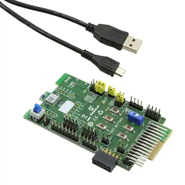
�RN487x PICtail / PICtail Plus Board
Figure 1: RN4870-SNSR (includes PICTail and Sensor Board)
1.2. Features
•
•
•
RN4870 fully certified Bluetooth Low Energy 4.2 RF Module.
+2dBM Maximum.
Transparent UART (serial data over GATT) connection over Bluetooth Low
Energy transparent serial data service.
•
•
Onboard dip switch block to set operating modes
PICtail Plus and PICtail interfaces to fully access RN4870 pins using external PIC
MCU
•
Embedded MCP2200 USB-UART converter to enable application mode and
programming interface to update firmware and configuration settings
2016 Microchip Technology Inc.
Preliminary-0824
Page 5
�RN487x PICtail / PICtail Plus Board
2. Interface Description
2.1. RN4870 PICtail Board Description
The PICtail interfaces are listed in figure 2 below. The PICtail can be used in standalone
mode powering it from external USB host, coin-cell battery, or from PIC Explorer
development board.
1. RN4870 Module
2. SW6 Power Switch
13. LED6 USB Power
Test Button
3. JP6 Power Switch
Indicator
CN1
CN3
14. J4 SPI Serial
Test Point
Flash interface
4. JP10 USB IO
15. J3 USB- UARTt
(MCP2200)
16. LED1 status
5. J10 VBAT Test
6. JP7 Test Button
17. JP8 LED1 supply
CN2
Connector
18. SW5 Reset Button
7. JP12 I2C Power
19. J1 Power Options
8. CN4 I2C Data
20. JP5 Test LED
9. JP13 I2C Reset
21. SW7
Configuration Mode
10. SW1-SW4, test
22.J2
buttons
GND Test Connector
11. PICTail Connector
28pin, 2x14 header
12 PICTail Plus, 2x15
Edge Connector
Figure 2 – RN4870 PICtail Interfaces
Interface Description
1. RN4870 Module
2. SW6 Power Switch used to wake module from deep sleep
3. JP6 Power test point (need use case)
4. JP10 Interface to MCP2200 USB/UART bridge
2016 Microchip Technology Inc.
Preliminary-0824
Page 6
�RN487x PICtail / PICtail Plus Board
5. J10 VBAT supply and test point
6. JP7 Test Button interface to SW1-SW4
7. JP12 Power to I2C bus (I2C features depends on firmware revision)
8. CN4 connector to I2C bus on RN4870 (I2C features depends on firmware revision)
9. JP13 I2C reset (I2C features depends on firmware revision)
10. SW1-SW4 test buttons
11. PICtail Interface (2x14 right angle header pin) for PIC18 Explorer Board
12. PICtail Pus Interface (edge connector) for PIC16 Explorer Board
13. LED6 external power from USB host
14. J4 SPI Serial Flash Interface
15. J3 UART connections. RTS/CTS jumpers must be closed when hardware flow
control is enable in module.
16. LED1 status indicator. See RN4870 data sheet for blink rate descriptions
17. LED1 power jumper; disconnects LED from RN4870 if external MCU is
monitoring this pin
18. SW5 – Hardware reset line to RN4870
19. J1 Power options for PICTail; PIC explorer board, USB host, Battery (coincell
CR2032) on back of board
20. JP5 Connections to test LED 1-4. This can be connected PIO lines or external
MCU
21. SW7 operating mode (1 – application mode runtime, ON – programming or
configuration to update firmware or configuration settings)
22. J2 Ground Test Connector
CN1, CN2, CN3 header pins to RN4870 module pins. The headers are used to connect
Sensor Board to PICtail board or as test points.
2.2. RN4871 PICtail Board Description
As shown in figure 3 below, the RN4871 PICtail uses the compact version of the RN487x
BLE module. Due to its smaller footprint, the RN4871 has less IO pins than the full size
RN4870 module. Consult the RN487x for the specific pin outs of RN4870 and RN4871.
Even thought the size of the module different, the command interface for both modules is
very similar. The user guide describes the difference when accessing RN4870 and RN4871
command pins.
2016 Microchip Technology Inc.
Preliminary-0824
Page 7
�RN487x PICtail / PICtail Plus Board
Figure 3: RN4871 PICtail
2.3. Sensor Board Description
The RN4870 PICtail (p/n RN-4870-SNSR) is provided with Sensor Board to demonstrate
the peripheral IO capabilities. The Sensor Board interfaces are illustrated in figure 4 below.
The Sensor Board is an accessory designed for RN4870 PICtail to demonstrate digital and
analog IO capabilities over Bluetooth Low Energy connections. In order to use the Sensor
Board with RN4870, it must be configured as described in section 4.0.
2016 Microchip Technology Inc.
Preliminary-0824
Page 8
�RN487x PICtail / PICtail Plus Board
1. Test Point Voltage
4. Light Sensor
2. Potentiometer ADC
Inputs
5. PUSH button
3. DIP switch block
Figure 4: Sensor Board Interfaces
Interface Descriptions
1. Test Point for ADC channels
2. Variable Resistor to drive ADC0 input
3. DIP Switch block to connect or disconnect sensors from RN4870
4. Light Sensor to drive ADC1
5. Push Button for PIO2
2016 Microchip Technology Inc.
Preliminary-0824
Page 9
�RN487x PICtail / PICtail Plus Board
3. RN487x Quick Start Guide
The simplest method to access the RN4870 adn is to connect it to a PC host that supports USB
CDC virtual COM (serial) ports. By using a terminal emulator application, simple ASCII
commands can be sent to the RN487x module. Interacting directly with the RN4870
Software Needed
•
PC Host supporting USB CDC virtual serial port.
o RN487x PICtail uses MCP2200 USB/UART Bridge. The drivers can be downloaded
from www.microchip.com/MCP2200.
•
Terminal Emulator application
o TeraTerm or CoolTerm is recommended.
•
Microchip SmartDiscover APP for iOS or Android
o Available on AppStore (iOS) or Google PlayStore (Android)
•
RN-4870-SNSR Support Package (RN4870-Sensor-Board-Support.zip)
o This is a collection of files and utilities to assist in configuring the sensor board. It
can be downloaded from www.microchip.com/RN4870 product page.
3.1. Connecting RN4870 to Host PC
To connect the RN4870 PICtail perform the following:
1. Ensure that the RN4870 PICtail is configured as follows
a. Close middle jumper on J1 to select USB power option
b. SW 7 to “1” position for application runtime mode
c. JP11 Tx and Rx jumpers closed position. Note if hardware flow control is enabled
then RTS and CTS jumpers must be installed.
2. Connect RN4870 to PC Host using micro USB cable.
a. Verify the virtual COM port is enumerated on host PC. If the COM port does not
enumerate, the MCP2200 drivers may be missing from the host PC. If needed, the
drivers can be downloaded from the www.microchip.com/MCP2200 web page.
b. Verify LED2 (blue) should be on indicating USB power
c. Press reset button SW5 and verify LED1 is flashing slowly
3. Start the Terminal Emulator software. In this example, TeraTerm will be used.
a. Configure the serial port settings using the enumerated COM to the following
settings:
2016 Microchip Technology Inc.
Preliminary-0824
Page 10
�RN487x PICtail / PICtail Plus Board
FIG 4: COM port settings for Terminal Emulator
4. Enter Command mode by sending the command escape sequence ‘$$$’. Pressing the ‘$’
three times will display put RN4870 in command mode and display a “CMD> “prompt.
a. When interacting directly with RN4870 using terminal emulator, it is useful to
enable local echo feature on the RN4870. Enter the ‘+’ character on the command
prompt. As shown below, the “ECHO ON” response is displayed. Any character sent
to RN4870 will be echoed back to sender to improve interactivity.
Fig 5: Command Prompt and ECHO ON response
5. Display the basic configuration settings press the “d” followed by [Enter] key (\r). As
shown below figure figure 6, the configuration settings may be changed. Refer to the
RN487x User Guide for detailed explanation of the commands.
Fig 6: Results of “D” to display basic configuration
3.2. Changing Settings Using Commands
The RN4870 PICtail is shipped with a default configuration which does not include any GATT
services, as noted by the results of the previous “d” (display basic configuration). The services
2016 Microchip Technology Inc.
Preliminary-0824
Page 11
�RN487x PICtail / PICtail Plus Board
value is set to “Services=00”. RN4870 can be discovered by a SmartDiscover APP. The
SmartDiscover APP is available for iOS devices on Apple APPStore™. Check the Google
PlayStore for Android version. To enabled built-in services and connect to the RN4870, follow
the steps below.
1. Connect the RN4870 PICtail to Host PC USB port
a. Using Terminal Emulator, open the COM port to RN4870
b. Type the command mode sequence “$$$” to enter command
c. Enter “+” for turn on ECHO. Refer to Figure 5.
2. To change the default name enable and enable GATT services, (Device Information Service
and Transparent UART), send the following commands.
a. “S-,BLE” to create a unique serialized name based on BTA address
b. “SS,C0” to enable Device Information Profile and Transparent UART sevices
c. “R,1” to reboot module so that configuration commands take effect
Figure 7: S- and SS command example
3. After any “Sx” set command(s) are issued, the RN4870 needs to be rebooted “R,1” for the
changes to take effect. To verify the configuration settings, perform the following:
a. Enter command mode by sending “$$$” sequence.
b. Enter “+” to turn on local echo for ease of use
c. Enter the “d” command to display the setting.
d. Note the name of the device “BLE-b1b0” where b1b0 low order bytes of BTA
address. In this example the Bluetooth is set to “BLE-C071”
e. Verify the services field is set to “C0”
Figure 8: Confirm New Settings in Command mode
2016 Microchip Technology Inc.
Preliminary-0824
Page 12
�RN487x PICtail / PICtail Plus Board
3.3. Connecting to RN487x using SmartDiscover APP
The RN487x features can be demonstrated by using the SmartDiscover APP. SmartDiscover is
available on iOS™ and Android™ devices, and can be downloaded from APPStore™ and Google
PlayStore™. The connect the RN487x using SmartDiscover
1. Using the RN487x PICtail as configured from section 3.2, connect it to host PC and enter
command mode using $$$
2. Download and install SmartDiscover APP on the device. See fig 9 below for example of
SmartDiscover APP Icon.
Figure 9: Smart Discover
3. Launch the SmartDiscover APP. The following examples will show the SmartDiscover on
the iOS device.
Figure 10: SmartDiscover (iOS)
4. As shown in figure 10, verify that the RN487x device name “BLE-b1b0” is displayed. In
this example, the device name is BLE-C071.
5. To initiate a connection to the RN487x device, select it from the list.
a. Verify the connection is established by if the GATT service view is shown as
2016 Microchip Technology Inc.
Preliminary-0824
Page 13
�RN487x PICtail / PICtail Plus Board
illustrated in figure 11.
Fig 11: GATT Service when Connected
b. The connection is also verified by “%CONNECT,1,” status message
returned by the RN487x UART. The is the address of the remote BT
device that initiated the connection. See the response in the terminal emulator as
shown in figure 12.
Figure 12: Connected Status Message
3.4. Creating Custom GATT Services
The RN487x module supports custom, or private, GATT services. Public GATT services are
defined by specifications published by the Bluetooth SIG. Private GATT services are defined by
2016 Microchip Technology Inc.
Preliminary-0824
Page 14
�RN487x PICtail / PICtail Plus Board
the user to host information stored in GATT characteristics. For more information on GATT
services, refer to Appendix A in the RN487x User Guide/Command Reference.
To create a private GATT service, enter the configuration commands listed below. The commands
can be entered as shown, or copied from configuration files and pasted into the terminal emulator.
The cut and paste method saves time and minimize keyboard entry errors. The configuration text
files are contained in the RN4870 Sensor Board Support package, which can be downloaded from
www.microchip.com/RN4870.
1. Connect the RN4870 PICtail to Host PC USB port
a. Using Terminal Emulator, open the COM port to RN4870
b. Type the command mode sequence “$$$” to enter command
c. Enter “+” for turn on ECHO.
2. Set Factory Default
a. Enter “SF,1” and verify module is reboots after command is entered.
3. Create the private GATT service with three characteristics by entering the commands below.
PS,4D6963726F636869702D524E34383730
PC,BF3FBD80063F11E59E690002A5D5C501,02,02
PC,BF3FBD80063F11E59E690002A5D5C502,02,02
PC,BF3FBD80063F11E59E690002A5D5C503,18,04
a. These commands can be entered manually by typing each line followed
key from the file “3.4-GATT-service.txt”, or each line can be copied and pasted into
terminal emulator.
The PS command creates the GATT service, identified by UUID 16-byte value
4D6963726F636869702D524E34383730.
The PC commands created the characteristics in the service. Each characteristic is
identified by the following UUIDs: BF3FBD80063F11E59E690002A5D5C501,
BF3FBD80063F11E59E690002A5D5C502, BF3FBD80063F11E59E690002A5D5C503.
The second parameter is the characteristic property (refer to table 1 in Appendix C),
and the third parameter is size of the data value of characteric.
b. Reboot the module using “R,1” command to ensure the new GATT takes effect.
4. To Verify the GATT Service was configured correctly
a. Enter command mode ($$$) after rebooting the module
b. Issue the LS command to list the services
c. The response should be as illustrated below in fig 13.
2016 Microchip Technology Inc.
Preliminary-0824
Page 15
�RN487x PICtail / PICtail Plus Board
Figure 13: Private Services display from “LS” command
3.5. Accessing GATT Service using UART Commands and
SmartDiscover
The result of the LS (List Service) command is shown in figure 3.4. A custom GATT service
(UUID: 4D6963726F636869702D524E34383730) with three characteristics identified by low order
bytes C501, C502, C503 from the 128bit UUID. Each characteristic is assigned a 16-bit handle
(0072-0075). Handles are used to efficiently reference and identify characteristics in the GATT
service. A 16-bit handle is easier to manage than 128-bit UUID. Note that there are two handles
references for C503 characteristic.
As indicated by the 08 property value (see table 1) in reference 0076 for characteristic C503, this
characteristic has the write property enabled. Likewise, reference 0077 has the notification
property 10 enabled. This means that to write a value to characteristic C503, reference 0076 is
used. To enable client notifications on this characteristic, reference 0077 is used.
The following examples show how to read and write GATT characteristic values by using UART
Commands
a. To write a value to GATT server characteristic, C501, use the server handle write
(SHW) and server handle read (SHR) commands with 0072 reference as first
parameter, following by hex byte values.
Figure 14: Writing and Reading GATT value by handle reference
b. It is also possible to access GATT server over a Bluetooth Low Energy Connection
using SmartDiscover APP. Launch the SmartDiscover APP and connect to the
2016 Microchip Technology Inc.
Preliminary-0824
Page 16
�RN487x PICtail / PICtail Plus Board
RN487x board configured with the private GATT from section 3.4. In this example,
the device “BLE-C071” is used. Follow the steps in figure 15 below to read the
value of GATT characteristic C501. 1). In steps 1 & 2, tap “>” command followed
by the “Read” command in step 3. The characteristic value will be read from
RN4870 into the Smart Discover APP.
1
3
2
Figure 15: Using SmartDiscover to Read GATT Characteristic Value.
3.6. Reading Sensor Board Peripheral IO Ports Using UART Commands
The RN487x module has digital and analog peripheral inputs and outputs. Refer to the data sheet
for full description of IO interfaces, and the User Guide sections 2.4.24, 2.6.5-2.6.8 for
configuration details. Peripheral IO can be accessed through direct UART commands or over
Bluetooth Low Energy connection by associating a GATT characteristic with a peripheral input or
output. In this section, accessing peripheral IO on sensor board connected to RN4870 PICtail.
UART commands will be used read peripheral IO on sensor board, as illustrated in figure 16.
1. Connect the sensor board to the RN4870 PICtail as shown in figure 1.
2. Set Factory Default to default Peripheral IO functions
a. Using Terminal Emulator, open the COM port to RN4870
b. Type the command mode sequence “$$$” to enter command
c. Enter “SF,1” and verify module is rebooted after command is entered.
3. The following commands set the RN4870 IO pin to configuration illustrated below in figure
16:
a. Type the command mode sequence “$$$” to enter command
b. Enter “+” to enable local echo
2016 Microchip Technology Inc.
Preliminary-0824
Page 17
�RN487x PICtail / PICtail Plus Board
c.
d.
e.
f.
g.
Enter “SW,01,00” ADC input port 01 used by light sensor
Enter “SW,02,00” ADC input port 02 used by potentiometer
Enter “SW,03,00” configure digital IO port connected to LED
Enter “SW,04,09” to configure digital IO trigger connected to push button
Enter to “SF,1” to reboot module for these setting to take effect
LED
“SW,03,00”
Potentiometer
“SW,02,00”
Switch
“SW,04,09”
Light Sensor
“SW,01,00”
Figure 16: RN4870 Pins used by Sensor Board Interface
4. After the IO ports are configured and module is rebooted from previous SF,1 performed the
following commands shown in figure 17 to read and write peripheral IO.
2016 Microchip Technology Inc.
Preliminary-0824
Page 18
�RN487x PICtail / PICtail Plus Board
Figure 17: Commands to write and write Sensor Board IO
2016 Microchip Technology Inc.
Preliminary-0824
Page 19
�RN487x PICtail / PICtail Plus Board
4. Using the RN4870 Sensor Board
The RN-4870-SNSR sensor board needs to be configured before it can be used as BLE peripheral.
The RN4870 is configured as follows to enable the Sensor Board peripheral, and allow the
BLESensor App to communicate with the RN4870:
•
•
Peripheral IO port to sensors is configured using SW command
A GATT (Sensor Board) service must defined to hold the values from peripherals for read
access from a (GATT) client.
•
Similarly, when a client writes a value to a GATT characteristic in a peripheral, there must
be a method for the peripheral to write the value destined for characteristic into the
peripheral port.
•
A GATT client on a central (GAP) device is used to access the GATT characteristics in the
peripheral, which is an RN4870 with sensor board. The GATT client for the sensor board is
an SmartPhone APP call BLESensorAPP. Keep in mind that it is possible to use another
RN4870 as the client to access the RN4870 sensor board peripherals.
The critical function of associating GATT characteristic with a peripheral is performed by the
RN4870 scripting capability.
The RN4870 can be configured manually following the instructions in section 4.1 to 4.4.
Alternatively, the RN4870 can also be configured by using the PC Utility
(RN4870_SensorBoard_Cfg_Cmd.exe) described in section 4.5. The PC utility sends automates the
commands listed in sections 4.1 to 4.4. Go directly to section 4.5 to skip manual configuration if
that is desired.
4.1. Configuring the RN4870 Module Settings
The sensor board can be configured by entering the following commands below. Alternatively to
manually typing, the configuration commands can be located in section 9.1 to 9.3 of this
document. Each command can be copied to Clipboard via CTRL-C, and sent into RN4870 via
TeraTera ALT-V paste command.
1. Connect the RN4870 PICtail to Host PC USB port
a. Using Terminal Emulator, open the COM port to RN4870
b. Type the command mode sequence “$$$” to enter command
c. Enter “+” for turn on local echo.
d. Enter “WP” to pause any running scripts
e. Enter “WC” to clear any previous script
f. Enter “PZ” to clear any previous user defined GATT service
g. Enter “SF,1” to factory default module settings and verify module reboots after
2016 Microchip Technology Inc.
Preliminary-0824
Page 20
�RN487x PICtail / PICtail Plus Board
command is entered.
h. RE-enter command mode by typing “$$$”
i. Enter “+” for turn on local echo.
2. Configure Module Features
a. Enter “S-,RN4870” to serialize Bluetooth name
b. Enter “SS,80” to enable Device Information Profile
c. Enter “SR,4040” to enable scripting start on PWR_ON event and disable command
prompt.
d. Enter “SW,01,00” to configure ADC input port 01 used by light sensor
e. Enter “SW,02,00” to configure ADC input port 02 used by potentiometer
f. Enter “SW,03,00” to configure digital IO port connected to LED
g. Enter “SW,04,09” to configure digital IO trigger connected to push button
h. Enter “R,1” to reboot module
i. Re-enter command mode by typing “$$$”
j. Enter “+” for turn on local echo
k. Enter the “d” display setting as show in Fig 18 below. The GW command is used to
return the current IO configuration.
Figure 18: RN4870 Module Settings Configuration
4.2. Sensor Board GATT Service
The collected data from RN4870 peripheral IO are stored in the characteristics of a custom GATT
service that is accessed by the Sensor Board BLE Client APP. To create the Sensor Board GATT
Service, enter the commands below while in command mode.
1. Enter “PS,AD11CF40063F11E5BE3E0002A5D5C51B” to create 128-bit UUID to
identify the GATT Service.
2. Enter “PC,BF3FBD80063F11E59E690002A5D5C501,10,02” to declare a two byte
characteristic with notify property enabled. This characteristic stores the value of
2016 Microchip Technology Inc.
Preliminary-0824
Page 21
�RN487x PICtail / PICtail Plus Board
ADC channel used for light sensor.
3. Enter “PC,BF3FBD80063F11E59E690002A5D5C502,10,02” to declare a two byte
characteristic with notify property enabled. This characteristic stores the value of
ADC channel used for potentiometer.
4. Enter “PC,BF3FBD80063F11E59E690002A5D5C503,18,14” to declare 20 byte
value used to manage both push button state (virtual LED in APP) and the LED
blink rate on sensor board. Both notify and write properties are enabled for this
characteristic.
5. Enter “PC,BF3FBD80063F11E59E690002A5D5C504,10,02” to declare a two byte
characteristic with notify property enabled. This characteristic stores the value of
ADC channel used for RN4870 internal temperature sensor.
6. Enter “PC,BF3FBD80063F11E59E690002A5D5C505,10,02” to declare a two byte
characteristic with notify property enabled. This characteristic stores the value of
ADC channel used for the RN4870 internal battery voltage sensor.
7. Enter “R,1” to reboot RN4870 module
8. Type “$$$” to enter command mode
9. Enter “+” to enable local echo
10. Enter the “LS” (list services) to display Sensor Board GATT Service as shown in
figure 19 below:
Figure 19: Sensor Board GATT Service declared in RN4870
As illustrated by the LS command result in figure 19, a custom GATT service has been
created in the RN4870 module. Note that each characteristic is assigned a 16-bit handle,
where each character has a value in handle and property handle. The characteristic value
and properties are access by short, and more efficient 16-bit handle, instead of the
128-bit UUID value. For example, two handles 0072, and 0073 associated with the
2016 Microchip Technology Inc.
Preliminary-0824
Page 22
�RN487x PICtail / PICtail Plus Board
GATT characteristic BF3FBD80063F11E59E690002A5D5C501. A GATT client, such
as a SmartPhone APP, uses 0072 is used read/write characteristic values, while 0073 is
used to enable/disable the notify property. The next step is to transfer the sensor values
from peripheral IO into the GATT characteristics. This is done with RN4870 scripting
feature described in the next section.
4.3. Transferring Sensor Data into GATT Service using Scripting
The Sensor Board GATT service was defined in the previous section. In order to populate the
characteristics with data from sensor board peripherals, and conversely, transfer values received
from GAP Client into peripheral IO channels, the RN487a scripting feature is used. For more
details about the scripting capabilities please refer to the RN4870/71 User Guide, document
DS50002466A.
The script that drives the peripheral values to and from GATT service is written into RN487x
non-volatile via the UART. First the module is put into script entry mode, the Script, which is a
series of text commands separated by carriage returns. The actual script is displayed in sec 9.3. It
can be copied to clip board, and pasted in UART using TeraTera. Similarly, the PC Utility will
load it into RN4870.
To manually load the Sensor Board script, follow the instructions below. Steps 4.1 and 4.2
1. Connect the RN4870 PICtail to Host PC USB port and Enve
a. Using Terminal Emulator, open the COM port to RN4870
b. Type the command mode sequence “$$$” to enter command
c. Enter “+” for turn on ECHO.
2. Enter Script Entry mode
a. Enter “WW” command to put RN4870 in script entry mode. Note that this command
does NOT return an “AOK” response.
b. Copy the script text from section 9.3 into clipboard using Ctrl-C.
c. From TeraTerm, paste this Script using Alt-V (Paste) command. A dialog window
showing the script text from clipboard should display as shown figure 20 below
2016 Microchip Technology Inc.
Preliminary-0824
Page 23
�RN487x PICtail / PICtail Plus Board
Fig 20: TeraTerm Clipboard
Figure 20: Sensor Board Script displayed from Clipboard
d. Press OK to load the script into the RN4870.
e. After the script is pasted into the RN4870, exit Script Entry mode by pressing the
ESC key. An “AOK” response is send to terminal indicating exit from Script mode.
The script entry is show in Figure 21 below.
Figure 21: Completed Sensor Board Script
f. Enter the “R,1” to reboot the RN4870. After the reboots the Sensor Board is now
ready to use. The script event handlers can be seen scrolling on TeraTerm display as
show below in Figure 22:
2016 Microchip Technology Inc.
Preliminary-0824
Page 24
�RN487x PICtail / PICtail Plus Board
Figure 22: Sensor Script running
4.4. BLESensorAPP SmartPhone APP
The RN4870 Sensor Board is a BLE Peripheral that advertises a GATT service to BLE Central
devices. In this demonstration, the BLE Central device is a SmartPhone Application named
BLESensorAPP. It is available for iOS and Android platforms via iTunes APPSTORE, and
Google PLAYSTORE respectively. Search for the “Microchip BLESensorAPP”, and download
the APP matching the icon in figure 23 below.
Figure 23: BLESensorAPP icon
The BLESensorAPP requires that the sensor board be configured as described in sections 4.1 to
4.3.
1. Verify the sensor board is attached to the RN4870 PICtail as shown in figure 1.
2. Verify the jumpers and switches match those in figure 2
a. SW7 must in be in the “1” position
3. Power the PICtail via USB
a. Connect the RN4870 PICtail board to power up.
b. Verify LED1 blue should blink with long interval.
4. Launch the APP from the SmartPhone. Note that in this example, the iOS version is used as
shown in right hand side of figure 24 below.
5. The BLESensorAPP will attempt to connect to the first RN4870 Sensor board that it
2016 Microchip Technology Inc.
Preliminary-0824
Page 25
�RN487x PICtail / PICtail Plus Board
discovers. Once connect the APP main user interface is displayed.
Figure 24: BLE Data Flow from Sensor Board Peripheral IO to BLESensorAPP
Figure 24 illustrates the data flow from RN4870 Sensor Peripheral IO to SmartPhone APP. The
data moving from the Sensor Board to the APP is performed by GATT Notifications. The script
polls the sensor values, such as Switch, Light Meter, and writes the values into the appropriate
GATT Characteristic. If the values changes, a GATT Notifications is sent to BLESensorAPP
where the APP updates the GUI.
BLE data can also be transferred from BLESensorAPP into the RN4870, and later processed by
the script to write a received value into Peripheral output channel. In the Sensor board demo, the
user uses to slider control on the APP to select a blink rate value. The value is written to the
GATT characteristic in the RN4870. The sensor script monitors the Characteristic for incoming
data then extracts the value which is subsequent written to the PWM output peripheral to control
blink LED blink rate.
For more information on BLE GATT data transfers refer to section 8.0: BLE Primer.
2016 Microchip Technology Inc.
Preliminary-0824
Page 26
�RN487x PICtail / PICtail Plus Board
4.5. RN4870 Provision Utility
The RN4870 Provision Utility can be used to provision/configure the RN4870 Bluetooth Low
Energy (BLE) module from a Windows Host PC using a wired connection over Universal
Asynchronous Receiver/Transmitter (UART) interface. RN4870 Provision Utility is used to program
the RN4870 PICtail with the configuration and script to work with the Sensor board and the
BLESensorAPP.
The utility comes with a few pre-built provision options that can be selected using the ‘Provision
File’ drop down menu. Alternatively, a custom configuration XML file can be imported in to the
utility to provision the RN4870 module.
Detailed instructions for provisioning the RN4870 module and creating custom configuration XML
file are provided in the RN4870 Provision Utility Help files. Examples of the provision XML file are
provided in the Examples folder.
Download the RN4870 Provision Utility from www.microchip.com/RN4870. Extract the
contents into a separate folder on the host PC. The contents of the extracted folder include
the RN4870 Provision Utility executable, RN4870 Provision Utility Help files and
example configuration XML files. This utility requires the MCP2200 USB/UART CDC
drivers. The driver is also available from the web page. Install the driver if needed.
Note: While the provisioning is in progress, RN4870 should not be disconnected and the process
should not be interrupted. If the provisioning process is interrupted the RN4870 module might not
be configured as desired.
To configure a RN4870 PICtail with a Sensor Board plugged in
1. Verify the sensor board is attached to the RN4870 PICtail as shown in figure 1.
2. Verify the jumpers and switches match those in figure 2
3.
4.
5.
6.
a. SW7 must in be in the “1” position
Connect the RN4870 PICtail board to a Windows PC using the micro USB cable.
a. Verify LED1 blue should blink with long interval.
Wait for the RN4870 board to enumerate as a Serial Port device successfully.
After the RN4870 board enumerates as a Serial Port device, open the Device Manager on
Windows PC and note down the COM port number assigned to the RN4870 board under
‘Ports’.
Run the RN4870 Provision Utility (RN4870ProvisionUtility.exe) on the Windows PC.
2016 Microchip Technology Inc.
Preliminary-0824
Page 27
�RN487x PICtail / PICtail Plus Board
Figure 25: Configuration Utility Main window
7. Ensure that the RN4870 board is still connected to the Windows PC and successfully
enumerated. Click ‘Scan’ button to scan for all the UART COM ports available on the
Windows PC. Note: Ensure that the COM port on which the RN4870 board is enumerated is
not already open by another application like a Serial Terminal application.
8. Click on the drop down menu of the ‘UART COM Port’ and select the correct COM port
which is assigned to the RN4870 board to be provisioned.
Figure 26: Configuration Utility: Select COM port
A set of pre-built provision options for RN4870 module are provided. Choose the
RN4870_Sensors_Demo_1.xml XML file from the ‘Provision File’ drop down menu.
2016 Microchip Technology Inc.
Preliminary-0824
Page 28
�RN487x PICtail / PICtail Plus Board
Figure 27: Configuration Utility: Select XML File
Note: Use a valid BLE Provision XML (.xml) file only. Please refer Provision XML File
section below to create a custom BLE Provision XML file.
9. With the RN4870 board still connected, COM port and the RN4870_Sensors_Demo_1.xml
XML file selected, click ‘Provision’ button to start the RN4870 provisioning process. The
progress bar shows the progress of the provisioning process.
Figure 28: Configuration Utility: Configuring Module
10. After the provisioning process is complete, an information dialog window pops up to
inform a successful provisioning of the RN4870 module.
Note: After the provisioning is successful, the RN4870 will automatically reboot and retain
the provisioned configuration.
2016 Microchip Technology Inc.
Preliminary-0824
Page 29
�RN487x PICtail / PICtail Plus Board
5. PIC Configuration Library
The BM7x Configuration Library provides a set of functions for RN487x to create command packets
to update its Bluetooth parameter table, perform pairing procedure, configure a subset of parameters
in application mode, set the module to different operating modes. The RN487x uses the UART
interface for configuration and data transfer. The RN487x configuration and events are defined as
command and response protocol packets. A command packet is sent to RN487x over UART to
update a parameter. Response packet is received from RN487x over UART for the command issued.
RN487x also sends out event packets over UART when a defined event occurs. The PICtail Plus and
PICtail interface on the RN487x PICtail board is used to configure the RN487x module over the
UART using the BM7x Configuration Library with an external PIC MCU and to send and receive
raw data over UART. The PICtail interface can also be used to access the UART and the GPIOs on
the RN487x module.
5.1. Using BM7x Configuration Library with RN487x PICtail
The RN487x PICtail plugs into the Explorer 16 Development Board with a PIC32/PIC24
Plug-In-Module (PIM) or PIC18 Explorer Board with PIC18 PIM. The BM7x Configuration
Library demo is an example application that can be programmed in to the PIC32/PIC24/PIC18 to
configure and control the RN487x module on the PICtail board.
Download/Install
1. Download the BM7x Configuration Library installer from www.microchip.com/RN4870
2. Install the library on a Windows PC.
3. Refer to the getting_started.htm file for more information on the MPLABX workspace.
Programming/Debugging
1. Plug-in the PIC Plug-In-Module (PIM) into the relevant Explorer Development Board based
on the hardware combination selected for evaluation.
Note:If using PIC32MX795F512L PIM, ensure that on jumpers J1 and J2 on the PIM, pins 2
and 3 are connected using a jumper to select the CAN configuration and all jumpers on J9 and
J10 on the PIM are not connected.
2. Plug-in the RN487x PICtail Plus board in to the Explorer Development Board with the
RN487x module facing towards the PIC PIM as shown in Fig 18 or Fig 19 based on hardware
combination used.
3. Optionally a debug UART port can be connected to a PC terminal emulator program.
Note:On the Explorer 16 Development Board, debug UART is available on the DB9 UART
serial connector P1. On the PIC18 Explorer Board, the debug UART will need to be manually
tapped from pins RG1/TX2 and RG2/RX2 on J5 header using external wiring.
4. Provide power through the 9V power input port available on the Explorer Development
Board.
2016 Microchip Technology Inc.
Preliminary-0824
Page 30
�RN487x PICtail / PICtail Plus Board
Figure 29: Explorer 16 Development Board with RN4870 PICtail Plus
Figure 30: PIC18 Explorer Board with RN4870 PICtail Plus
2016 Microchip Technology Inc.
Preliminary-0824
Page 31
�RN487x PICtail / PICtail Plus Board
5. Program the PIC32 with the ‘bm7x_configure_demo_xc32.hex’ or PIC24 with the
‘bm7x_configure_demo_xc16.hex’ or PIC18 with the ‘bm7x_configure_demo_xc8.hex’ in
the ‘precompiled_hex’ sub-directory.
6. Alternately open the ‘bm7x_configure_demo.X’ MPLABX workspace provided using the
MPLABX IDE and compile and program or enter debug mode either selecting the PIC32
workspace configuration or the PIC24 workspace configuration or the PIC18 workspace
configuration based on the hardware combination selected as shown in the figure below:
Figure 31: MPLAB Target configuration
7. Change the ‘#define BMXX_DEVICE xyz’ in main.c to
BM70_BLUETOOTH_DEVICE to work with RN4870.
Connecting/Running Demo
1. After setting up the hardware combination and programming the PIC using the above steps run
the PIC program.
2. Observe the RN487x configuration by putting break points in the workspace or by optionally
using the debug UART mentioned above.
3. Download and install the “BtChat_V1.0.3.apk” on the Android device from the BM7x PICtail
Plus webpage.
4. Open the “BtChat” app installed by the “BtChat_V1.0.3.apk” on the Android device.
5. Scan for the Bluetooth devices on the Android app.
6. Select your BM7x device listed in the scan list and click to pair and connect.
7. By default the application uses “Just Works” pairing. If using the “Passkey Entry” or “Passkey
Yes/No Confirm” mode then provide the passkey or confirmation using the debug UART port.
For RN4870 module, please refer the documentation for the pairing modes supported.
8. Once connected, the data can be transmitted from BM7x through the debug UART port to the
“BtChat” app over Bluetooth link.
9. Enable “Show Rx Text” option in the “BtChat” app “Setting”. The “BtChat” app can send data
back to the BM7x which is later received through the debug UART.
2016 Microchip Technology Inc.
Preliminary-0824
Page 32
�RN487x PICtail / PICtail Plus Board
6. Appendix A: Updating RN4870/71 PICTail Firmware
Firmware for the RN4870/71 PICTail can be updated using a PC Tool isupdate.exe over the
USB port. The latest RN4870/71 firmware images isupdate.exe firmware load is available
from the product page at www.microchip.com/RN4870.
To update the firmware on the RN4870 PICTail follow the instructions below.
1. Download the firmware zip file from product web page and extract the contents. The zip
file contains the ISUPDATE.EXE utility and a folder the firmware images are included.
2. Connect the PICTail to the PC host using the micro USB cable. Verify that the
3. Set SW7 is set to “ON” position
4. Press SW5 reset button and verify LED1 is non-flashing blue indicating RN487x module is
in programming mode.
5. Launch the ISUPDATE.EXE application
a. Select the COM port used by PICTail board
b. Verify other settings (baud, memory type, address) are set as shown in Figure 32.
Figure 32: ISUPDATE.EXE firmware update utility
6. Press Connect button and verify the “Port connect -> COMxx” is displayed in text box.
7. Verify firmware update is completed successfully. The “End of Write Memory” message is
displayed.
2016 Microchip Technology Inc.
Preliminary-0824
Page 33
�RN487x PICtail / PICtail Plus Board
8. Press “Disconnect” button to close COM port. The “port disconnect” message is displayed
as indicated below.
Figure 33: Disconnect ISUPDATE.COM from RN487x Module
9. Set SW7 to the 1 position for application run time mode
10. Open TeraTerm and connect to the module
11. Press SW5 to reboot module. Verify the %REBOOT% message is displayed
12. Enter command mode by sending “$$$” escape sequence.
13. Enter the “V” command and verify firmware version, as illustrated in figure
2016 Microchip Technology Inc.
Preliminary-0824
Page 34
�RN487x PICtail / PICtail Plus Board
7. Appendix B: Schematics and BOM
7.1. RN4870 PICTail Schematic
2016 Microchip Technology Inc.
Preliminary-0824
Page 35
�RN487x PICtail / PICtail Plus Board
2016 Microchip Technology Inc.
Preliminary-0824
Page 36
�RN487x PICtail / PICtail Plus Board
7.2. RN4870 PICTail BOM
Oty
3
Designator
Description
Manufacturer
Manufacturer Part Number
C8, C10, C27
CAP CER 1uF 10V 10% X5R
Murata
GRM155R61A105KE15D
SMD 0402
Electronics
North America
1
2
C12
C17, C28
CAP TANT 47uF 16V 10%
AVX
TPSC476K016R0110
0.11R SMD C
Corporation
CAP CER 1uF 16V 10% X7R
TDK
C1608X7R1C105K
CAP CER 12pF 50V 1% NP0
Murata
GRM1555C1H120FA01D
SMD 0402
Electronics
SMD 0603
2
C19, C21
North America
3
3
1
C20, C23,
CAP CER 0.1uF 16V 10% X7R
AVX
0603YC104KAT2A
C24
SMD 0603
CN1, CN2,
CON HDR-2.54 Male 1x9 Gold
Samtec
TSW-109-07-G-S
CN3
5.84MH TH VERT
CN4
CON HDR-2.54 Female 2x5
Samtec Inc.
SSQ-105-02-G-D-RA
FERRITE 300R@100MHz 2A
Laird-Signal
MI0805L301R-10
SMD 0805
Integrity
GOLD TH R/A
2
FB1, FB2
Products
1
J1
CON HDR-2.54 Male 2x3 Gold
Samtec
TSW-103-08-L-D
Samtec
TSW-104-08-L-D
FCI
68001-106HLF
Sullins
PBC14DBDN
Samtec
TSW-104-07-G-S
FCI
77311-118-02LF
FCI
68001-108HLF
Lite-On
LTST-C193TBKT-5A
5.84MH TH VERT
3
J2, J3, J10
CON HDR-2.54 Male 2x4 Gold
5.84MH TH VERT
1
J4
CON HDR-2.54 Male 1x6 Gold
5.84MH TH VERT
1
J8
CON HDR-2.54 Male 2x14 Gold
5.84MH TH R/A
2
JP5, JP7
CON HDR-2.54 Male 1x4 Gold
5.84MH TH VERT
4
1
JP6, JP8,
CON HDR-2.54 Male 1x2 Gold
JP12, JP13
5.84MH TH VERT
JP10
CON HDR-2.54 Male 1x8 Gold
5.84MH TH
1
LED1
DIO LED BLUE 2.8V 20mA
2016 Microchip Technology Inc.
Preliminary-0824
Page 37
�RN487x PICtail / PICtail Plus Board
15mcd Clear SMD 0603
4
1
LED2, LED3,
DIO LED YELLOW 2.1V 20mA
LED4, LED5
6mcd Clear SMD 0603
LED6
DIO LED RED 1.8V 40mA
Lite-On
LTST-C190YKT
Lite-On
LTST-C190KRKT
FCI
10118193-0001LF
KOA Speer
RK73H1ETTP3300F
Panasonic
ERJ-3GEYJ472V
Panasonic
ERJ-2RKF2201X
Panasonic
ERJ-6GEYJ103V
Panasonic
ERJ-6GEYJ471V
Panasonic
ERJ-6GEYJ102V
10mcd Clear SMD 0603
1
P1
CON USB2.0 Micro-B Female
SMD R/A
4
2
R2, R26,
RES TKF 330R 1% 1/16W SMD
R27, R28
0402
R8, R25
RES TKF 4.7k 5% 1/10W SMD
0603
3
1
R10, R11,
RES TKF 2.2k 1% 1/10W SMD
R13
0402
R20
RES TKF 10k 5% 1/8W SMD
0805
1
R21
RES TKF 470R 5% 1/8W SMD
0805
1
R24
RES TKF 1k 5% 1/8W SMD
0805
1
R29
RES TKF 4.7K 1% 1/16W 0402
KOA Speer
RK73H1ETTP4701F
1
SK1
BATT HOLDER COIN 1 TH
Keystone
1053
CR2450
Electronics
SW1, SW2,
SWITCH TACT SPST 12V
C&K
SW3, SW4,
50mA RS-282G05A3-SM RT
Components
SWITCH TACTILE PUSH
ROKI
ON-OFF 6 PIN
ELECTRONICS
6
RS-282G05A3-SM RT
SW5, SW8
1
SW6
PS07-22L-PF
CO., LTD.
1
1
SW7
X1
SWITCH DIP 1 SPST 24V 25mA
Wurth
418117270901
418117270901 SMD
Electronics Inc
CRYSTAL 12MHz 8pF SMD
NDK
NX3225SA-12.000000MHZ
MCHP RF BLUETOOTH
Microchip
RN4870-V/RM118
RN4870-V/RM118 MODULE-33
Technology Inc
MCHP ANALOG LDO 3.3V
Microchip
MCP1700T-3302E/TT
Technology Inc
NX3225SA
1
1
FP2
U2
2016 Microchip Technology Inc.
Preliminary-0824
MCP1700T-3302E/TT
Page 38
�RN487x PICtail / PICtail Plus Board
SOT-23-3
U10
1
MCHP INTERFACE USB UART
Microchip
MCP2200-I/SS SSOP-20
Technology Inc
MCP2200-I/SS-ND
7.3. RN4870 Sensor Board Schematic
7.4. RN4870 Sensor Board BOM
Oty
Designator
Description
Manufacturer
Manufacturer Part Number
2
C1, C2
CAP CER 0.010uF 25V 10% X7R
Yageo
CC0603KRX7R8BB103
Taiyo Yuden
LMK107BJ105KA-T
Preci-Dip
801-87-009-10-001101
Lite-On Inc
LTST-C191KGKT
Bourns Inc.
3386P-1-203TLF
SMD 0603
1
C3
CAP CER 1uF 50V 10% X5R SMD
0603
3
1
J1, J2,
CON HDR 2.54 Female 1x9 Gold
J3
7MH TH VERT
LD1
DIO LED GREEN 2V 30mA 35mcd
Clear SMD 0603
1
P1
RES Variable CC 20K 10% 1/2W TH
3386P1-xxxT Knob
2016 Microchip Technology Inc.
Preliminary-0824
Page 39
�RN487x PICtail / PICtail Plus Board
1
R2
RES TKF 12k 1% 1/10W SMD 0603
Yageo
RC0603FR-0712KL
1
R3
RES TKF 100R 1% 1/10W SMD 0603
Panasonic
ERJ-3EKF1000V
1
S1
SENSOR PHOTOCELL 27-60KOHM
Advanced
PDV-P8104
Photonix Inc
1
1
SW1
SW2
SWITCH TACT SPST 12V 50mA
C&K
PTS645SM43SMTR92
PTS645SM43SMTR92 LFS SMD
Components
LFS
SWITCH DIP 4-POS SLIDE SMD 6V
Copal
CHS-04TB
Electronics
Inc.
3
TP1,
MISC, TEST POINT MULTI
TP2,
PURPOSE MINI BLACK
Keystone
5001
TP3
2016 Microchip Technology Inc.
Preliminary-0824
Page 40
�RN487x PICtail / PICtail Plus Board
8. Appendix C: Bluetooth Low Energy Primer
8.1. GAP Roles: Peripheral and Central
When two BTLE devices want to be connected, one should be in Central role and the other in
Peripheral role. The Peripheral device advertises to show its connectable status, while Central
device scans service advertisements, and if needed, will initiate a connection to Peripheral
device. Once connected, either end of connection can choose to bond. Once bonded, all
security related key will be saved and security process will be waived when reconnecting.
Bonded peripheral device could only perform direct advertise, therefore, no longer to able to
connect to device other than its bonded peer.
8.2. GATT Service: Client and Server
Similar to Bluetooth Classic, BTLE uses the concept of profiles to ensure interoperability
between different devices. As illustrated in figure 2, BTLE profiles are collection of services.
All BTLE services are built on top of Generic Attribute Profile (GATT), where GATT defines
accessibility of attributes called characteristics. The main functionality of BTLE profiles,
therefore, is built around the characteristics. For those devices that maintain the value of
characteristics in a service, such device is the server of the service. On the other hand, those
devices that acquire data from their peer are called client.
Each service and its characteristics could be identified by their Universally Unique Identifier
(UUID). The UUID can be a short form (16bit) or long form (128bit). As specified by
Bluetooth Core Specifications, all Bluetooth SIG adopted (public) services and
characteristics have short UUID (16bit), while user defined private UUID are in long
form (128bit). For the details of Bluetooth SIG adopted services and characteristics, please
refer to https://developer.bluetooth.org/gatt/profiles/Pages/ProfilesHome.aspx.
The accessibility of each characteristic is defined by 8-bit characteristic property in bitmap
format, as shown in table 1 below.
Property
Bitmap Value Description
Extended
Property *
0x80
Additional property available
Authenticated
Write *
0x40
Write characteristic with authentication from
client to server
Indicate
0x20
Indicate value of characteristic with
acknowledgement from server to client
Notify
0x10
Notify value of characteristic without
acknowledgement from server to client
2016 Microchip Technology Inc.
Preliminary-0824
Page 41
�RN487x PICtail / PICtail Plus Board
Write
0x08
Write value of characteristic with
acknowledgement from client to server
Write without
response
0x04
Write value of characteristic without
acknowledgment from client to server
Read
0x02
Read value of characteristic. Value is sent from
server to client
Broadcast *
0x01
Broadcast value of characteristic
Table 1. Characteristic Properties
* Currently not supported in RN487x
As shown in figure xx, below, the GATT Client can access the characteristics in the GATT
Server in the peripheral device. When connected, the client reads the GATT Server service
and characteristic UUIDs. The characteristic values can be accessed by the GATT client using
Write, Read, Indication and Notifications.
Write-REQ allow client to update characteristic values on the Peripheral’s GATT server. The
write requests can be performed using RN4870 CHW and CUW commands. See section 3.8 for
more details on GATT characteristic access commands.
A Write-CMD message performs an unacknowledged write from a client to server. This is
allowed for Transparent UART writes on the RN4870 when SR,0100 command is used.
A client sends Read-REQ read a characteristic value on the Peripheral’s GATT server. The
write requests can be performed using RN4870 CHR and CUR commands.
Notifications and Indications are unsolicited updates sent from Server to Client. The client
must enable the notification and indication on a characteristic to receive the updates. On the
RN487x, this done by using the CUW or CHW command to write non-zero value to the
Notification Characteristic. When RN487x in client mode receives a notification, and
%WC,hhhh,ddddddd% message is return on UART in command mode.
2016 Microchip Technology Inc.
Preliminary-0824
Page 42
�RN487x PICtail / PICtail Plus Board
RN487x
[GAP Peripheral, GATT Server]
GATT Server Service
BTLE Device
GATT Client Write-REQ
[GAP Central, GATT Client]
ACK-Write-REQ
Central-Client devices
Public Service 16-bit UUID
Characteristic 16-bit UUID
Characteristic
UUID
Properties &16-bit
Descriptors
Characteristic
UUID
Properties &16-bit
Descriptors
Properties & Descriptors
Private Service 128-bit UUID
Characteristic 128-bit UUID
Characteristic
UUID
Properties &128-bit
Descriptors
Characteristic
128-bit
UUID
Properties & Descriptors
Properties & Descriptors
include the following:
GATT Client Write-CMD
GATT Client Read-REQ
Read-RESP
GATT Notification
•
SmartPhone
•
Host PC
•
Tablet
•
RN4020 module
•
RN4870 module
•
Other BTLE device
GATT Indication
ACK-Indication
Figure XX: GATT Service in RN487x
2016 Microchip Technology Inc.
Preliminary-0824
Page 43
�RN487x PICtail / PICtail Plus Board
9. Appendix D: Sensor Board Configuration Command Text
The following text can be copied
9.1. RN4870 Module Settings
WP
WC
PZ
S-,RN4870
SR,4040
SS,80
SW,01,00
SW,02,00
SW,03,00
SW,04,09
R,1
9.2. RN4870 Sensor Board GATT Service
PZ
PS,AD11CF40063F11E5BE3E0002A5D5C51B
PC,BF3FBD80063F11E59E690002A5D5C501,10,02
PC,BF3FBD80063F11E59E690002A5D5C502,10,02
PC,BF3FBD80063F11E59E690002A5D5C503,18,14
PC,BF3FBD80063F11E59E690002A5D5C504,10,02
PC,BF3FBD80063F11E59E690002A5D5C505,10,02
R,1
2016 Microchip Technology Inc.
Preliminary-0824
Page 44
�RN487x PICtail / PICtail Plus Board
9.3. Sensor Board Script
@PW_ON
IA,Z
SM,2,0000
SM,1,0002
%0078=?FUNC1
?FUNC1
[,1,1,$PM1,$PM2
@DISCON
SM,1,0000
SM,2,0000
SM,3,0000
R,1
@CONN
SM,1,0000
SM,2,0000
SM,3,001A
@TMR1
IA,Z
IA,FF,CD00FE14AD11CF40063F11E5BE3E0002A5D5C51B000C000D
SM,2,000F
@TMR2
IB,Z
IB,FF,4C000215AD11CF40063F11E5BE3E0002A5D5C51B000C000DC5
SM,1,0004
@TMR3
$VAR1=@,0
SHW,0072,$VAR1
$VAR1=@,1
SHW,0075,$VAR1
$VAR1=@,5
SHW,007B,$VAR1
$VAR1=@,4
SHW,007E,$VAR1
SM,3,001A
@PIO1L
SHW,0078,0001
@PIO1H
SHW,0078,0000
2016 Microchip Technology Inc.
Preliminary-0824
Page 45
�