物料型号:
- 型号包括SMBG5913B至SMBG5956B和SMBJ5913B至SMBJ5956B。
器件简介:
- 这些表面安装的2.0瓦特Zener二极管提供了从3.3到200伏的电压选择,并有10%、5%和2%的容差选项。
- 与轴向JEDEC注册的1N5913至1N5956系列相比,除了更高的2.0瓦特功率等级外,具有相同的电气特性。
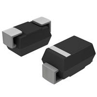
引脚分配:
- SMBG系列采用Gull-wing设计,在DO-215AA封装中提供可见的焊接连接。
- SMBJ系列采用J-bend设计,在DO-214AA封装中允许更大的PCB安装密度。
参数特性:
- 工作温度范围:-65°C至+150°C。
- 热阻:结到引脚35°C/W,结到环境100°C/W。
- 稳态功率耗散:2.0瓦特。
- 正向电压:200毫安时为1.2伏。
功能详解:
- 这些二极管在宽广的工作电流和温度范围内调节电压。
- 它们对静电放电不敏感,符合MIL-STD-750方法1020。
- 能够承受高浪涌应力。
应用信息:
- 适用于高密度和低剖面安装,提供宽广的Zener电压范围。
封装信息:
- 提供SnPb镀层引脚或符合RoHS标准的亚光锡镀层。
- 封装类型包括DO-215AA Gull-wing和DO-214AA J-bend。